N1000 QUICK START
Please contact SVSi technical support @ svsiav.com or 256.461.7143 x9900 for any
installation issues. Visit our support webpage at support.svsiav.com.
Distribution Switching Recording Windowing Wall Processing Control
Southern Vision Systems, Inc. 256. 461.7143 www.svsiav.com
SVSi is a trademark of Southern Vision Systems, Inc. in the United States and other countries.
800DOCN1000QSREV2.0
Made in the USA.
Troubleshooting Guidelines
Optional Accessories:
N9312 12V External Power Supply N9101 Rack Mounting Wings
N9102 1RU Rack Shelf (holds 2 cards) N6123 Dual-Channel Networked Video Recorder
N9206 2RU Card Cage (holds 6 cards) N1510 4x1 Windowing Processor
N9312 12V Power Supply N9382 1RU 12V/16-Unit Power Supply
Problem Possible Solutions
Video is not transmitting. • Verify that the encoder TX Enable setting is turned
on. (Encoders ship from the factory with their video
output turned off by default.)
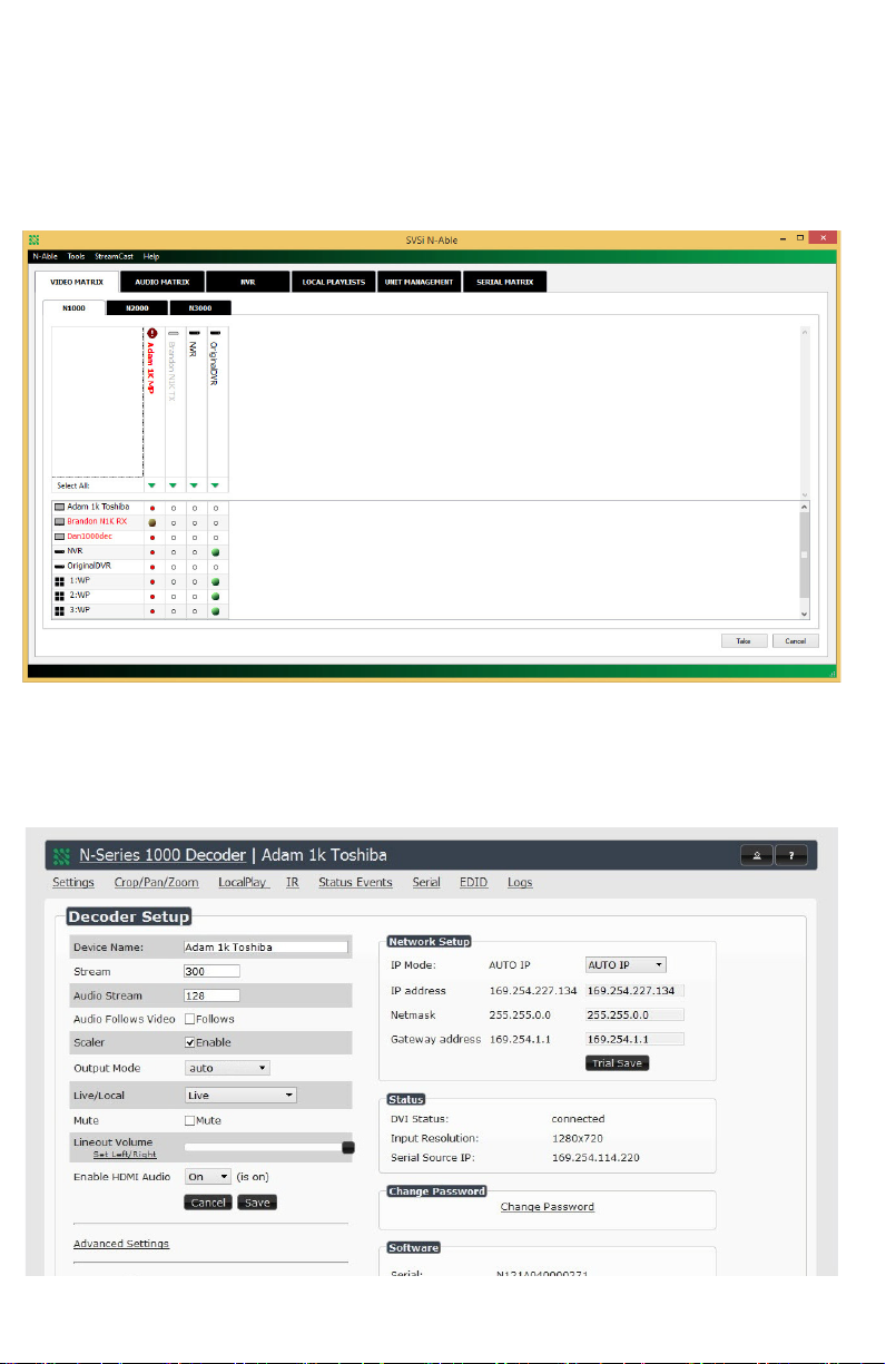
“Local Play” graphic is displayed. • Verify decoder is assigned to view a valid stream in
the N-Able matrix.
• Verify decoder is currently in “live play” mode
(black text on matrix view).
• Verify network is properly configured and set up. If
needed, connect encoder directly to decoder to
verify network issues.
“Host Play” graphic is displayed. • Verify encoder is in live play mode (black text in
matrix).
• Verify source is attached and is outputting a valid
signal (DVI light on encoder is lit).
“Unsupported Resolution” graphic
is displayed.
• Change source resolution to a valid resolution (try
720p60).
• Verify cabling is correct.
“Copy Protected Content” screen is
displayed.
• Contact SVSi technical support.
Black screen/no graphic is
displayed.
• Set decoder to local play. If the local play graphic
does not appear, check the display input settings
and cabling.
• If local play appears, set decoder to live play and
verify network is configured properly.
No Audio is detected. • If there is no audio on all decoders, verify audio
settings are correct on encoder.
• If there is no audio on a single decoder, verify
audio settings are correct on decoder.
Congratulations on the purchase of your N1000 series product — part of SVSi’s family of
Networked AV products. An SVSi Networked AV system comprises video and/or audio encoders,
decoders, and other network accessories including recording solutions, multi-window processing,
audio-only end points, and system controllers. The system allows you to distribute HD Video,
Audio and Control across a gigabit Ethernet network. Options are available for recording,
playback, and wall processing.
Network Bandwidth per video stream = 880Mbs. All units must be home-runned to a gigabit Ethernet layer-3
switch supporting IGMP-query with Immediate Leave. Please contact SVSi to obtain a pre-configured switch or
for details on configuring an existing switch.
Analog or digital video is input through the DVI-I connector on the N1000 encoder and converted to
network packets for output through the RJ45 connector. Audio can be input as embedded digital
audio through the DVI-I connector or as balanced/unbalanced analog audio through the 5-pin
phoenix connector. Both encoder and decoder can be powered either +12V externally with optional
power supply or by power-over-Ethernet (PoE).
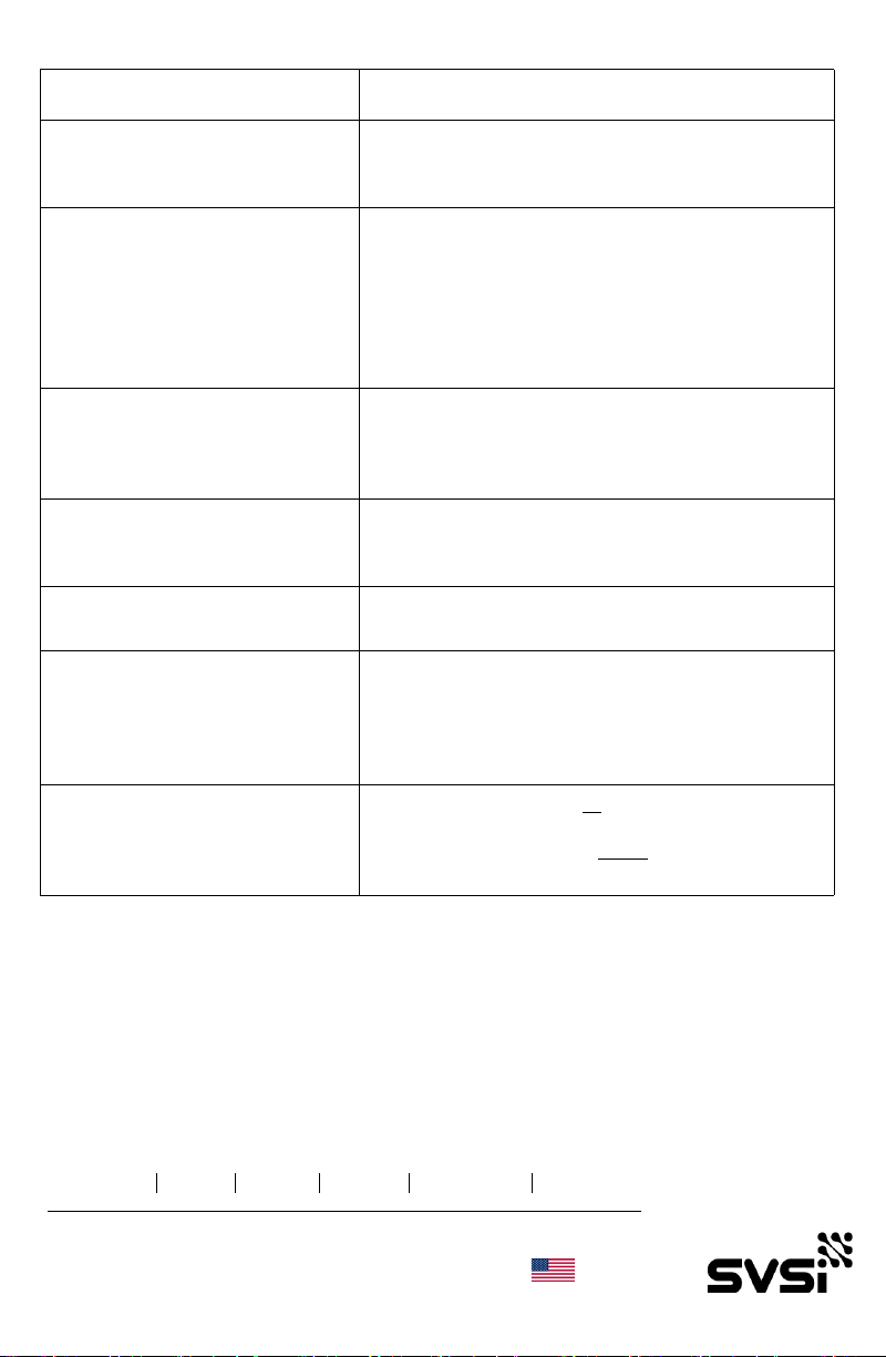
The N1000 series decoder accepts the network packets and reconstitutes synchronized video and
audio for display through its DVI-D port. Digital-only video is output by the decoder. Audio can be
output as embedded digital audio through the DVI-D connector or as balanced/unbalanced analog
audio through the 5-pin phoenix connector. IR and serial commands can be transmitted by either
encoder or decoder using SVSi's free N-Able configuration software, SVSi's N8000-series
controller, or using third party controllers. IR and serial ports are not pass-through and must use a
central controller to direct commands to each device.
1
N1000 Series Encoder Rear View
7.888
1 2 3 4 5 6 7
1.050
1) 12VDC Input (not needed with PoE)
2) Status Indicators
3) RJ45 Auto-Sensing Gigabit Ethernet
Switch Port — PoE
4) IR 2-Pin Phoenix Connector
5) RS232 Connection
6) Analog Audio Input Connection
7) DVI-I Digital Input
8) Analog Audio Output Connection
9) DVI-D Digital Output
7.888
1.050
1 2 3 4 5 8 9
N1000 Series Decoder Rear View