Power Swager
5
Section I
Swagelok Power Swager
Operating Instructions
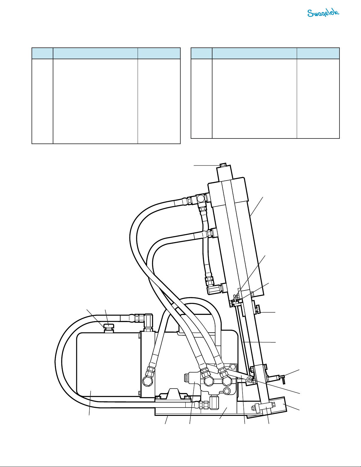
Note: The swager may be lifted by rigging a suitable fabric
sling around the guide bars and hydraulic cylinder below the
top bar.
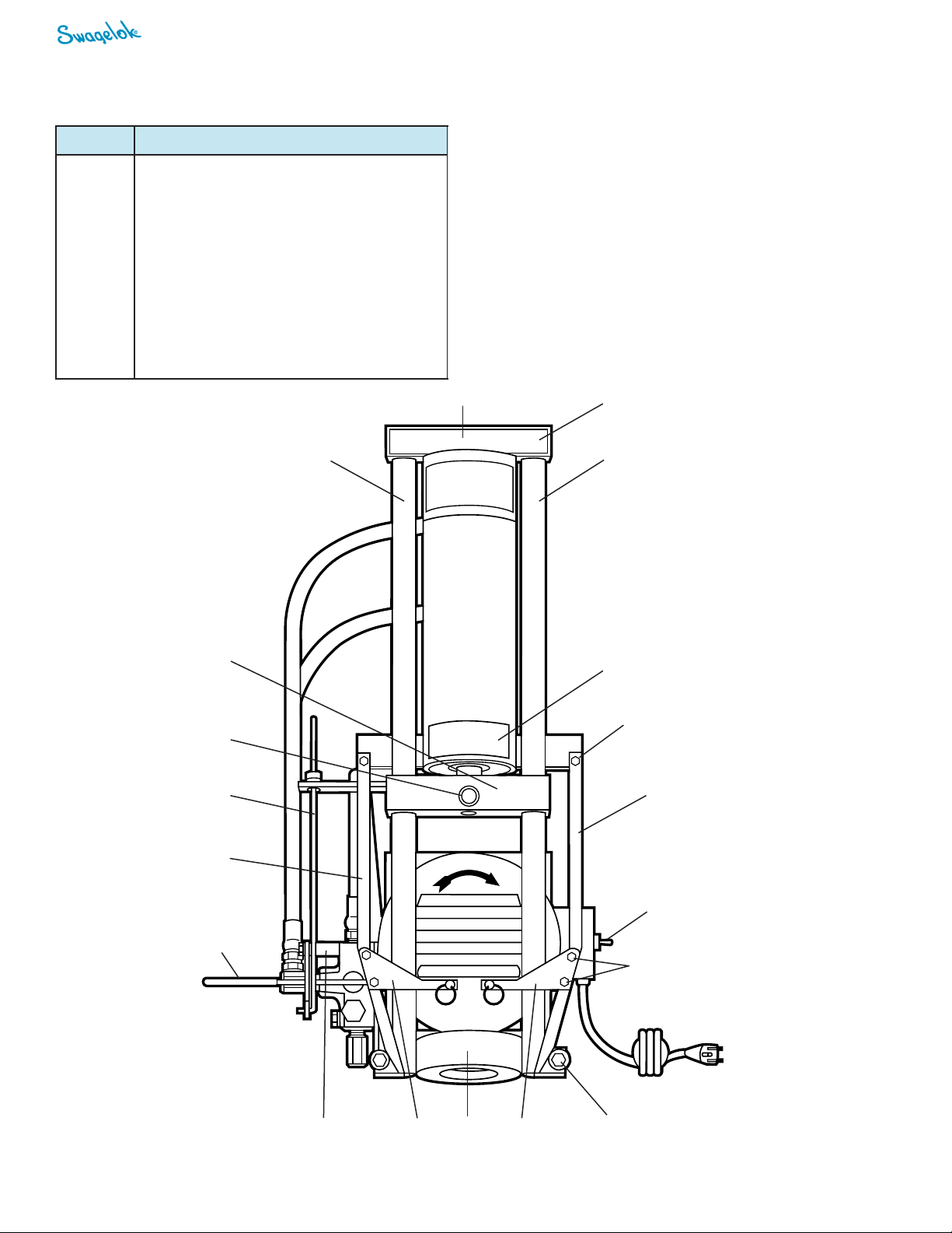
Breather Cap Installation
The breather cap is shipped in the bag attached to the swager.
1. Remove the plug from the oil reservoir. Note: Do not discard
the plug. To reduce loss of hydraulic oil through the breather
cap, reinstall the plug when shipping the swager or when
tilting it or placing it on its side.
2. Check the hydraulic fluid level. It should be 1 to 1 1/2 in.
(25 to 38 mm) below the breather hole. Note: The swager
is shipped with the proper type and amount of oil in the
reservoir. However, if additional fluid is required, it should be
equivalent to Mobil®D.T.E. 26 (325 SUS at 100°F, 37°C)
3. Install the breather cap.
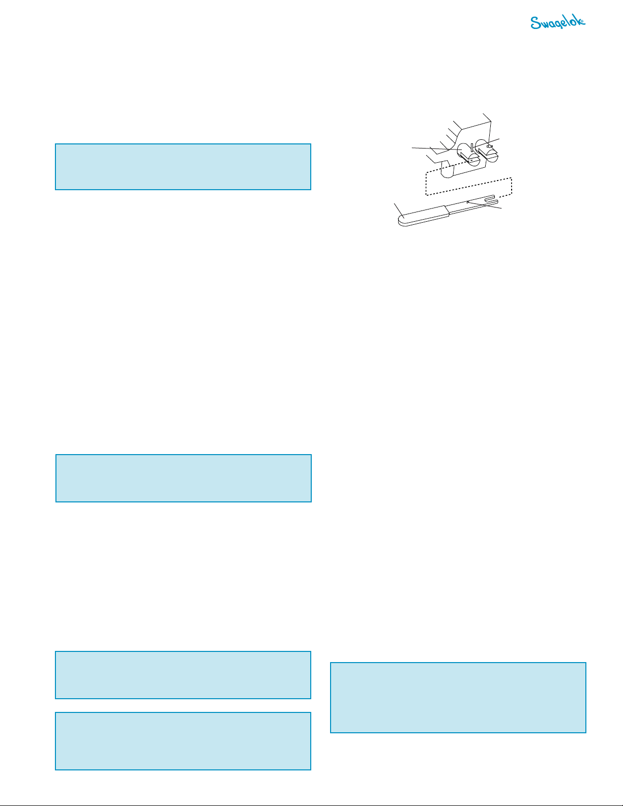
Note: The valve is on the left side of the swager.
2. Position the valve handle so that the hole is in line with the
roll pin in the valve stem. (See drawing above.)
3. Use a hammer to carefully tap the roll pin down through
the hole in the handle until the pin is flush with the top of
the stem.
Dies and Pushers
Use the chart in Section II to determine the proper dies and
pushers needed for each end connection. The dies have been
adapted to fit in the die lifting fingers on the swager.
Adjustment of the Automatic
Return Stop Position
1. Install the proper dies and pusher for the hose and end
connection desired.
2. Turn on the swager.
3. Pull the valve handle toward you to bottom the pusher onto
the dies.
4. Push the valve handle in the opposite direction, raising the
pusher.
5. Insert the hose and end connection assembly up between
the dies and so that it can be held in the pusher. Note: See
Section II for hose pre-assembly instructions.
6. Push or pull the valve handle so that the bottom of the end
connection shell is 3/4 to 1 in. (19 to 25 mm) above the top
of the dies.
7. Loosen the thumb screw on the trip rod collar.
8. Allow the trip rod collar and trip rod to descend to the low-
est position.
9. Tighten the thumb screw.
10. Remove the hose and connection.
11. Run the swager a full cycle to make sure the trip rod prop-
erly releases the valve handle.
The swager is now ready for use.
Note: Different sizes and types of hose and end connections
may require additional adjustments.
Valve Handle Installation
The handle is shipped in the bag attached to the swager.
1. Raise and secure the trip rod mechanism (2, 3, 4, 8,
and 12) out of the way of the swager.
!Caution
Always adjust the trip rod collar so that the return
stop functions before the pusher block retracts into
the bottom of the cylinder.The swager may be
damaged otherwise.
!Caution
Do not lift or move the swager by its die lifting fingers,
arms, or hydraulic hoses.
!Caution
Never connect the green or green/yellow wire to a live
terminal!
!Caution
The motor should always be disconnected from the
power source whenever servicing the machine or
performing troubleshooting.
Roll pin hole
Valve handle
Valve
stem
Roll pin
Setup
1. Place the swager on a sturdy platform or table.
2. Position the swager so the die bowl clears the platform or
table to allow clearance for the moving parts of the swager.
3. Secure the swager with suitable fasteners through the bolt
holes located in the angle iron supports on the base of the
swager.
Electrical Requirements
■The electrical requirements for the swager are as follows:
■110/220 V (ac)
■13/6 A
■1 phase 60 Hz, wired for 110 V
■The swager must be grounded to guard against electrical
shock. The unit is equipped with a three-wire conductor and
three-prong plug to fit a grounded receptacle.
■When turning on the swager unit for the first time, verify that
the motor is rotating in the direction of the arrow on the
motor.
■A swager’s voltage can be changed from 110 to 220 V using
the wiring diagram on the inside of the switch cover. (It is
recommended that a qualified electrician perform this task.)
!Caution
Do not operate the swager without the breather cap
in place.