Swagelok RHPS Series User manual

RHPS Series
PRS(TC)12
User Manual
Read the complete manual before installing and using the regulator.

2
Contents
Introduction ................................................................................................................................................ 3
Installation .................................................................................................................................................. 4
Operation .................................................................................................................................................... 5
Maintenance ............................................................................................................................................... 6
Testing ......................................................................................................................................................... 7
Troubleshooting ......................................................................................................................................... 8
WARNING
Before removing a regulator from the system for service, you must
▪ depressurize system
▪ purge the system to remove any residual system media left in the regulator.

3
Introduction
Representative drawing of the standard PRS(TC)12
1 body assembly 15 clamp ring
2 spring housing 16 bottom springguide
4 valve assembly 17 knob assembly
5 o-ring 18 diaphragm
6 o-ring 22 diaphragm screw
7 bodyplug 23 ring
11 seat 24 nut
13 set spring 26 ball
14 valve spring 27 springguide

4
Installation
WARNING
When installing a Swagelok® self-venting regulator, position the vent connection or
line away from operating personnel. Operating personnel must protect themselves
from exposure to system fluids.
CAUTION
Do not use the regulators as a shutoff device.
Connections to System
Before connecting to system, verify the regulator is closed by turning the handle or adjusting knob:
▪ Counterclockwise, when viewed from above, until it stops for pressure reducing regulators,
▪ Clockwise, when viewed from above, until it stops for back-pressure regulators.
The preferred mounting position of the regulator is horizontal with the adjustment knob facing
upwards.
If grounding is required, connect a ground wire under a spring housing bolt.
If possible, the system should contain a filter.

5
Operation
Note: All handle directions are when viewed from above.
▪ Outlet and control pressure settings are obtained by adjusting the handle (or adjustment knob).
▪ To increase the outlet or control pressure, rotate the handle clockwise.
▪ To decrease the outlet or control pressure, rotate the handle counter-clockwise and vent the
downstream side of the regulator.
▪ The adjustment knob is provided with an anti-turnout locking ring, do not force it.
▪ Make the final setting in the direction of increasing pressure to obtain the most accurate set
points.
▪ Once fluid is flowing through the system, fine tuning may be required.
▪ Icing of the regulator at high flow rates or high pressure drops may occur if the gaseous media or
atmosphere contains moisture.
▪ An auxiliary upstream filter is recommended for use in all but the cleanest of media.
▪ Installation of a downstream pressure relief is recommended for regulator and system protection.
▪ If the shut-off valve at the outlet side is closed after changing the set pressure, the outlet pressure
will rise a little because of the closing force required for bubble-tight closing of the regulator.
▪ This phenomenon is usually referred to as the “lock-up” and does not indicate a problem
with the regulator.
▪ A decrease in the flow will result in a rise of the outlet pressure.
▪ An increase in the flow will result in a fall of the outlet pressure and is usually referred to as
the “droop”.
▪ This phenomenon does not indicate a problem with the regulator.
▪ A decrease of the inlet pressure will result in a rise of the outlet pressure.
▪ An increase of the inlet pressure will result in a fall of the outlet pressure.
▪ This phenomenon is usually referred to as the “dependency” or “supply pressure effect” and
does not indicate a problem with the regulator.

6
Maintenance
Required tools for maintenance
▪ a vice to fasten the regulator
▪ pincers to take out the O-rings
▪ a torque wrench
▪ an open end wrench, 13 mm
▪ an open end wrench, 24 mm
▪ an open end wrench, 36 mm
▪ an open end wrench, 50 mm
▪ media and temperature compatible lubricant for reassembling threaded parts
▪ media and temperature compatible lubricant for O-rings
▪ Snoop® liquid leak detector
Disassembly instructions
▪ Loosen the spring housing and remove the spring housing, spring, bottom spring guide with
diaphragm and clamp ring.
▪ Loosen the bodyplug to remove the valve assembly, seat and valve spring.
▪ Push the valve-assembly down when loosening the bodyplug.
▪ The force of the valve spring may cause galling of the threads.
Inspection of disassembled parts
▪ Check all parts for abnormal wear. Replace parts in case of doubt.
Points of attention before assembly
▪ All parts must be clean and undamaged before starting assembly.
▪ Swagelok recommends replacing all O-rings and the diaphragm before assembly.
▪ All threaded parts must be lightly lubricated before assembly to avoid galling of threads.
▪ All o-rings need to be lightly lubricated to improve the lifetime of the o-ring and the performance of
the regulator.
Assembly instructions
Follow the points for disassembly in reverse order to assemble the regulator.
Recommended torques
CAUTION
Only tighten the bolts or parts if the regulator is completely depressurized.
- Diaphragm screw 15.0 N·m (132 in.·lb)
- Bodyplug 50.0 N·m (442 in.·lb)
- Spring housing 50.0 N·m (442 in.·lb)

7
Testing
Check the regulator for leakage across the seat, with low and high inlet pressure.
Check the regulator for leakage across the diaphragm, with low and high outlet pressure.
Check the required outlet pressure range.
A well performing PRS(TC)12 is 100 % bubble tight.
If there is a leakage across the seat or the diaphragm, the damaged parts must be replaced.

Troubleshooting
Problem: The outlet pressure creeps up without turning the adjustment knob.
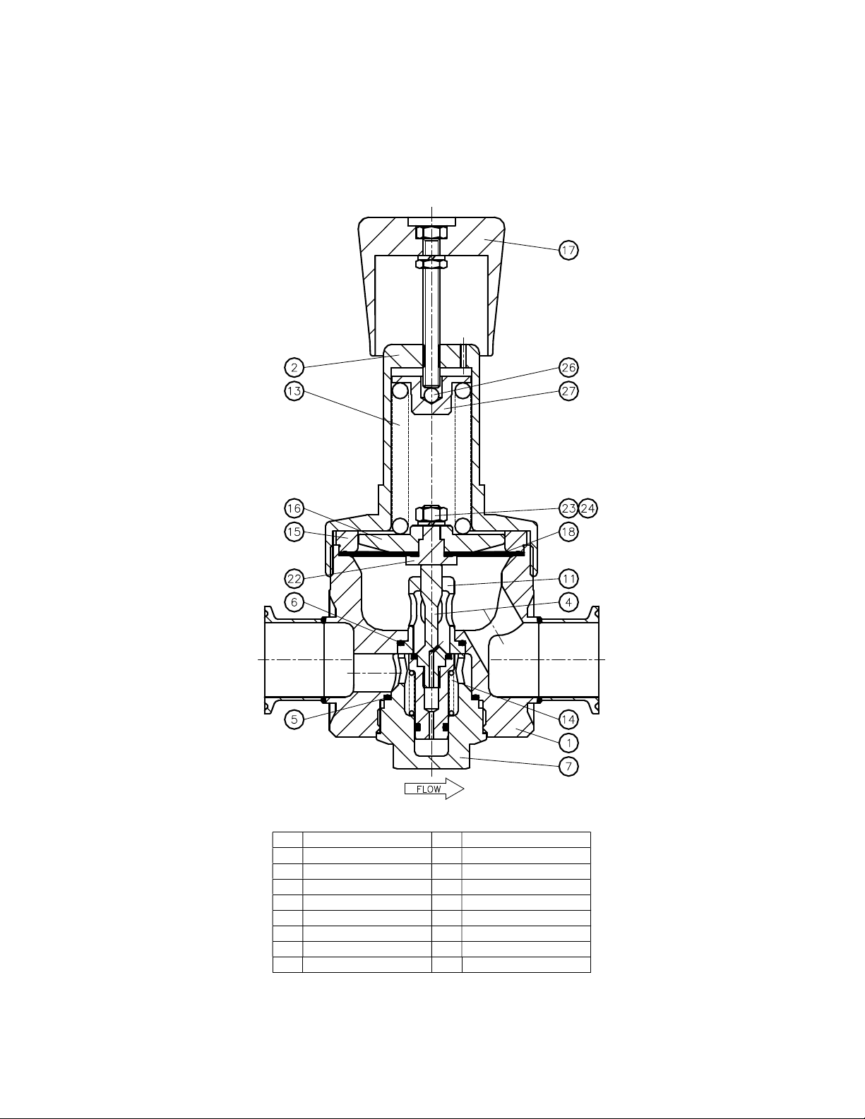
Cause: A damaged valve and/or seat.
Solution: Replace the valve and/or the seat.
Problem: Constant leak through the relief hole at the side of the spring housing.
Cause: A damaged diaphragm.
Solution: Replace the diaphragm.
Problem: The required outlet pressure can not be reached.
Cause: The inlet pressure is not high enough.
Solution: Make sure that the inlet pressure is sufficient.
Problem: The outlet pressure rises too much when going from a dynamic to a static situation.
Cause: There is too much flow in the dynamic situation.
Solution: A larger regulator is required.
Check the specific application data with the flow curves in our product literature, if available.
Problem: The outlet pressure does not drop if the adjustment knob is turned counterclockwise.
Cause: The regulator is non-venting.
Solution: A shut-off valve in the outlet line must be opened to reduce the outlet pressure.
Problem: The outlet pressure has changed without turning the adjustment knob.
Cause: Changes to the inlet pressure will result in changes to the outlet pressure.
Solution: Maintain a constant inlet pressure to the regulator. See section “operation” about dependency.
Problem: Controlled pressure drops off sharply even when the flow is within regulator capabilities.
Cause: The regulator filter element or system filter element is clogged.
Solution: Replace the filter element.
Warranty Information
Swagelok products are backed by The Swagelok Limited Lifetime Warranty.
For a copy, visit swagelok.com or contact your authorized Swagelok representative.
For additional information, see www.swagelok.com.
Swagelok, Snoop – Swagelok Company
© 2011-2021 Swagelok Company
MS-CRD-0173, RevA, October 2021
WARNING:
Do not mix/interchange Swagelok products or components
not governed by industrial design standards, including
Swagelok tube fitting end connections, with those of other
man
ufacturers.
Other manuals for RHPS Series
18
This manual suits for next models
2
Table of contents
Other Swagelok Industrial Equipment manuals
Popular Industrial Equipment manuals by other brands

Fire Extinguisher Valve Company
Fire Extinguisher Valve Company F-TEC3500EK installation manual

FIELDQUIP
FIELDQUIP XGB Series Owner's/operator's manual

Aventics
Aventics R434001268 Service information

Siemens
Siemens Sentron 3VA92 8-0VF30 Series operating instructions

WOOD'S POWR-GRIP
WOOD'S POWR-GRIP MR1611LDCO instructions

ABB
ABB SACE Tmax XT manual