manuals.online logo
Brands
  1. Home
  2. •
  3. Brands
  4. •
  5. Swann
  6. •
  7. DVR
  8. •
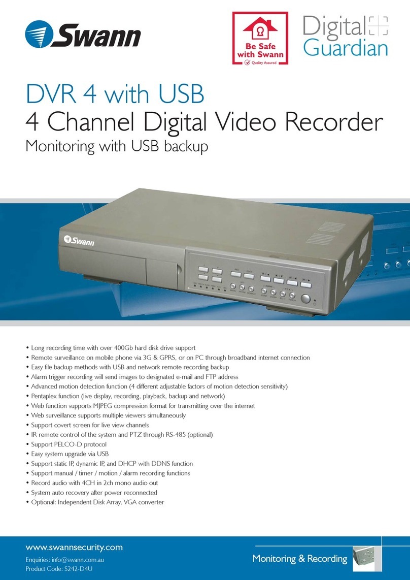
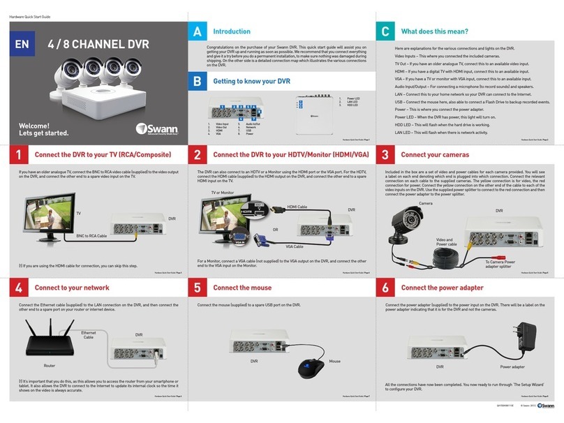
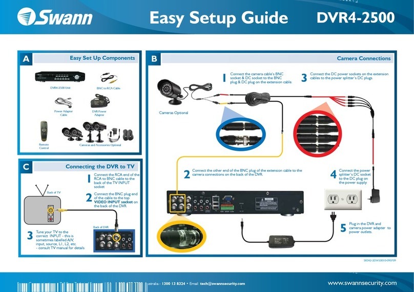
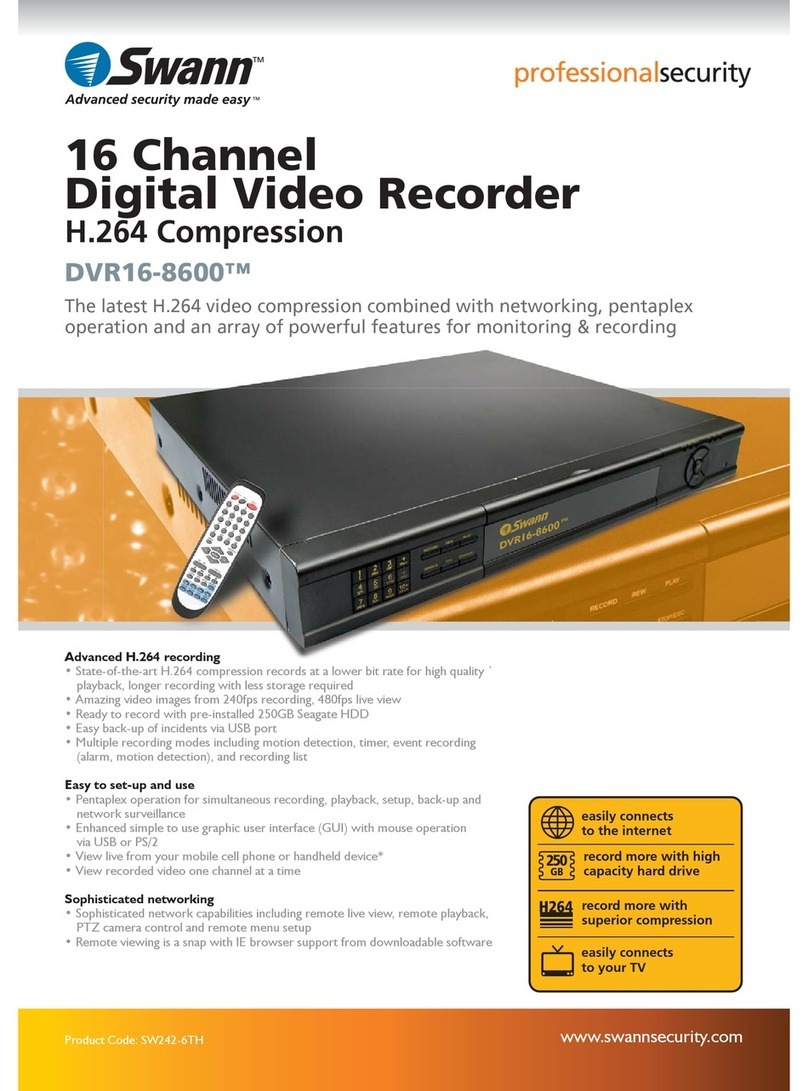
  9. Swann SW-R-DVR4NET User manual

Swann SW-R-DVR4NET User manual

This manual suits for next models

1

Other Swann DVR manuals

Swann PRO-series User manual

Swann

Swann PRO-series User manual

Swann M16 User manual

Swann

Swann M16 User manual

Swann DVR4-1525 Manual

Swann

Swann DVR4-1525 Manual

Swann DVR 2500 Mounting instructions

Swann

Swann DVR 2500 Mounting instructions

Swann DVR16-8900 User manual

Swann

Swann DVR16-8900 User manual

Swann NVR16-7200 User manual

Swann

Swann NVR16-7200 User manual

Swann DVR4-5500TM User manual

Swann

Swann DVR4-5500TM User manual

Swann PRO-series User manual

Swann

Swann PRO-series User manual

Swann dvr4-1500 User manual

Swann

Swann dvr4-1500 User manual

Swann 4480 Manual

Swann

Swann 4480 Manual

Swann NVR-8580 Series User manual

Swann

Swann NVR-8580 Series User manual

Swann 4-4350 Manual

Swann

Swann 4-4350 Manual

Swann DVR4-2500 User manual

Swann

Swann DVR4-2500 User manual

Swann PRO-series User manual

Swann

Swann PRO-series User manual

Swann DVR4-1000 User manual

Swann

Swann DVR4-1000 User manual

Swann DVR4-1000 SW242-DU2 User manual

Swann

Swann DVR4-1000 SW242-DU2 User manual

Swann M88200H210313E User manual

Swann

Swann M88200H210313E User manual

Swann SW242-SR4 User manual

Swann

Swann SW242-SR4 User manual

Swann SW-R-DVR16 User manual

Swann

Swann SW-R-DVR16 User manual

Swann DVR4-Alert SW242-DAL Dimensions

Swann

Swann DVR4-Alert SW242-DAL Dimensions

Swann DIGITAL GUARDIAN DVR4-NET User manual

Swann

Swann DIGITAL GUARDIAN DVR4-NET User manual

Swann DVR4-Alert SW242-DAL User manual

Swann

Swann DVR4-Alert SW242-DAL User manual

Swann 4500 Series User manual

Swann

Swann 4500 Series User manual

Swann DVR4-5100 Quick start guide

Swann

Swann DVR4-5100 Quick start guide

Popular DVR manuals by other brands

Pace TDC577X manual

Pace

Pace TDC577X manual

Zavio NQ2040 user manual

Zavio

Zavio NQ2040 user manual

KGuard Security KG-SHA104 user manual

KGuard Security

KGuard Security KG-SHA104 user manual

SanDisk V-Mate Quick manual

SanDisk

SanDisk V-Mate Quick manual

Panasonic WJND200 - NETWORK DISK RECORDER Setup instructions

Panasonic

Panasonic WJND200 - NETWORK DISK RECORDER Setup instructions

Hunt Electronic HVRM-T1600Q Install & user's guide

Hunt Electronic

Hunt Electronic HVRM-T1600Q Install & user's guide

Portwell PIVS-6104 user manual

Portwell

Portwell PIVS-6104 user manual

AVer EXR6004 Mini Quick user guide

AVer

AVer EXR6004 Mini Quick user guide

Security Labs SLD261 owner's manual

Security Labs

Security Labs SLD261 owner's manual

EverFocus ECOR 4 instruction manual

EverFocus

EverFocus ECOR 4 instruction manual

Xoro HRK 7550 user manual

Xoro

Xoro HRK 7550 user manual

FLIR M3100E Series instruction manual

FLIR

FLIR M3100E Series instruction manual

VTRACKPRO FPRO300 user manual

VTRACKPRO

VTRACKPRO FPRO300 user manual

RMRC FPV1000 manual

RMRC

RMRC FPV1000 manual

urmet domus 1093/004AHD instructions

urmet domus

urmet domus 1093/004AHD instructions

Toshiba D-VR3SU Service manual

Toshiba

Toshiba D-VR3SU Service manual

CMOS DOTCOM ANX-1670 manual

CMOS DOTCOM

CMOS DOTCOM ANX-1670 manual

Smarty BX4000 user guide

Smarty

Smarty BX4000 user guide

manuals.online logo
manuals.online logoBrands
  • About & Mission
  • Contact us
  • Privacy Policy
  • Terms and Conditions

Copyright 2025 Manuals.Online. All Rights Reserved.

INSTALLATION GUIDE
Table of Contents
If this device does not work when you first
plug it in, do not take it back to the store.
Contact the Swann Helpdesk using one of the Toll-Free
numbers shown on the back cover of this booklet.
Most problems can be quickly and easily fixed with a
quick chat with one of our friendly technical staff.
(Toll-Free available in the US and Australia only)
DVR4-Net
4 Camera
Digital Video Recorder
For Network & Web Monitoring
System Setup ......... 4
1. ......... 4
2. Accessing the Menu .................. 4
3. System Setup ........ 5
4. Time/Date Set ................ 5
5. HDD Format Set ......... ... 6
6. Factory Reset ...... ... .......... 7
7. Video Setup .................. 7
8. Name Setup .................. 7
9. Br /Con Setup ......... ....... 8
10. Record Setup ......... ........8
11. Network Setup ......... .....9
12. N Enable Set ........ .. .10
13. Mac Set ....................... 11
14. Alarm Setup ................11
15. Motion Detection Settings ....... 12
16. Area Set ...................... 13
17. Schedule Set ................ 13
18. Protocol Set .................14
Buttons On the Front Panel ............................................................................14
1. Recording/Playing Control Buttons Area ....... 1
2. Function Control Area ...........................15
3. Channel Choosing Control Area ...... .........16
Display Status While Running.............................................................................17
1. Screen Display While Running ..............................17
2. Screen Display While Playing ................................17
3. TRIP Display ........................................................ 18
System Connection............................................................................................. 18
1. Back Panel and Connection Terminals .................... 18
2. Video and Audio Connection ................................. 19
3. Alarm Connection ................................................. 19
4. Hard Disk Connection ........................................... 21
Quick User Guide................................................................................................22
1. Start the DVR4Net .............................................. ... 22
2. Turn off the DVR4Net ..............................................22
3. Normal Recording ................................................... 22
4. Alarm Recording ...................................................... 22
5. Time Recording ...................................................... 23
................................................................................... ............
Using the Setup Menu................................................................................ ........
...................................................................................
..........................................................................................
.............................................................................................
...................................................................................... .......
........................................................................ ..... .. .............
.............................................................................................. .
..............................................................................................
ight trast ........................................................................... .
........................................................................................ ......
.................................................................................... ..........
/W ............................................................................ ............ ......
..............................................................................................
..............................................................................................
............................................................................ .......
..............................................................................................
..............................................................................................
..............................................................................................
.................................................. ............ 4
.....................................................................
........................................................ ..........
......................................................
......................................................
......................................................
.................................................... .
....................................................
....................................................
....................................................
.................................................. .
..................................................
..................................................
..................................................
.................................................. .
6. Playback ....... ....... .. 23
7. Search Play ...... ....... ....... .. 23
8. Time Search ....... ... ....... .. 24
9. Event Search ....... ....... .. .. 25
10. Start Stop Search ....... ....... .. 25
11. Zoom Operation ....... ....... .. 26
12. PIP Operation ....... ....... .. 26
13. Information Display ....... ....... ... 27
14. Default Setting ....... ....... .. 27
1 . ....... ....... .. 2
1 . Remote Control ....... ....... .. 29
1 . Serial Port Control ....... ....... .. 29
1 . PC View Software Operation ....... ....... 29
Appendix A: Trouble shooting guide ..... 33
Appendix B: Serial port protocol .. 35
Appendix C: Record Time Table ..... . 37
Specifications ....................38
Exterior ....................38
.......................................... ..................... ........... ........................
................................ ............. ..................... ........... ............
.............................................. .................. ... ........... ............
............................................. ..................... .......... . .............
............................................... ..................... ........... .......
............................................... ..................... ........... .......
.............................................. ..................... ........... .............
............................................... ..................... ........... ...
............................................. ..................... ........... .............
5 Menu Option Table..................................... ..................... ........... ............. 8
6 ............................................. ..................... ........... ..........
7 .............................................. ..................... ........... ......
8 ............................................... ..................... ..
........................................................
................................................................. .
.......................................................... .... .
................................................................................
Dimensions.......................................................................
Security Notice
!Power supply
This Digital-Video-Recorder uses a DC 12 volt indoor power supply. The voltage of
the power must be verified before using. When the DVR4Net is not in use for a long
time, pull out the plug from the socket and disconnect the power.
!Security
This DVR4Net is for indoor use only; in order to avoid the danger of a short circuit or
electric shock, please do not expose the DVR4Net to rain or a moist environment. If any
solids or liquids enter the unit’s case, please turn off the power supply immediately, and
return the unit to a qualified technician to check the DVR4Net before restarting it.
This DVR4Net is a precise instrument; do not attempt to repair any component of the
DVR4Net by yourself as this will void warranty. If your DVR malfunctions in any way,
please contact the dealer in your area or Swann Tech Support directly.
!Installation
Please choose an appropriate site to install the DVR4Net, to ensure adequate ventilation
around the DVR4Net to avoid excessive heat. Do not install the DVR near a radiator,
ventilating trunk, heat sources, under direct sunshine, dusty locations or anywhere there
is a chance for mechanical vibration or impact.
!Video input: 4channels; video output: 2 channels.
!Audio input: 4channels; audio output: 1 channels.
!Four optional levels of image quality: very high, high, normal, low. Record and playback
frame rate change enable for recording.
!Compression mode: Modified MJPEG.
!Compatible with NTSC and PAL format.
!Supports alarm recording and time recording.
Multi-function searches: be able to distinguish different alarm records and time records
from ordinary records; be able to search by time, by segment or by event.
!Support various playback modes: pause, several fast forward and backward play modes.
!Support zoom, auto, and PIP function.
! 4 alarm input and 1 relay alarm output.
! Equipped with IR remote control
! Supports video loss and motion detection functions.
! Supports watermark image security protection.
! Triplex operation, can play back and search while it is recording. Both live and playback
pictures can be displayed on screen simultaneously.
! Totally independent from a PC platform, to give you the best opportunity to avoid loss of
recording from shutdown caused by the failure of other programs and operating system
malfunctions etc.
Name Quantity
4-channel Network DVR 1
IR Remote Control 1
Power Cable 1
Power Adaptor 1
BNC to RCA Female Adaptors 5
Hard Drive Tray and 2 Keys 1
Remote Viewing Software 1
User Manual 1
If any of these components are missing please contact your retailer
Features of this DVR
Contents list
System Setup 3. System Setup
When the cursor is moved to System Set, please push the enter button and the System Setup
window will appear, which is illustrated as below.
PLAY REPEAT: if you set this to “YES”, when you play the video to the end of the HDD, it will
automatically play the video from the beginning of the HDD again. If set to “NO”, it will stop
when the end of the recording is reached.
VIDEO SOURCE: switch the video format to suit the TV standard of your country, NTSC or
PAL.
BUZZER SOUND: buzzer switcher, if set to “OFF”, the buzzer will not work. The buzzer
sounds when motion is detected, if motion detection is enabled.
Before using the DVR, you must set up the system according to your needs and location;
otherwise the DVR4Net will run with the default settings which may be unsuitable. Refer to the
button description pages starting on page 14 to describe the button functions in detail.
1. Using the Setup Menu
When in setup mode, pushing the up button or down button, will move the cursor among the
various settings, continuous pushing will make the cursor move among the options one by one.
The selected option will display in a yellow color.
While choosing digital fields, e.g. year, month, day, hour, minute, second etc, push the left button
or right button, to move to the different digits of one field, continuous pushing will make it move
among digits one by one, and it can recur.
Please push the “+” or “-” button to change the value that the cursor shows, then push the
ENTER button to enter the sub menu and push Menu button to return to previous menu.
2. Accessing the Menu
If the DVR is in recording mode you cannot access the menu unless you stop record first. Press
the Stop button and enter the password to stop all functions then press the Menu button.
System setup is achieved through entering the setup menu, and then setting the options in each
feature’s window. To access the menu, please push Menu button on the front panel, it will display
the password input window.
The password is a random combination of 4 digits of “0-9”. The default is “0000”. To enter the
menu below, you have to input the correct password by pushing the digit buttons. If the
password you input is incorrect, the system will automatically return to the main screen. If you
want to cancel the input of the password, you can push the Menu button to return to the main
screen again. While inputting the password, in order to avoid being revealed to a bystander, the
password you input is displayed on the screen as “*” signs.
To change the password, please refer to “password change” section.
4. Time/Date Set
When the cursor is moved to Time/Date Set, push the Enter button and the TIME/DATE SET
window which is illustrated below will appear.
Please push up, down, left, and right buttons to move the cursor, push + and - buttons to
modify the value.
FORMAT: the date display format, which can be different for USA, EURO and Australian
users.
DISPLAY: if set to “OFF”, time will not display on the screen.
LOCAL: time display position on the screen.
5. HDD Format Set
When the cursor moves to HDD FORMAT SET, please push ENTER button, the System
Setup confirmation window will appear, which is illustrated below.
If you select “YES” and push the enter button, all video on the HDD will be deleted, if you do
not want delete all recordings, please select “NO”.
6. Factory Reset
When the cursor moves to Factory Reset, please push enter button, the confirmation window
will appear, which is illustrated as below.
If you select “YES” and push the enter button, all of the DVR settings will reset to default, if
you do not want to reset to the default settings, please select “NO”.
7. Video Setup
When the cursor moves to Video Setup, please push enter button, the Video Setup window
will appear, which is illustrated as below.
BOUNDARY: boundary line color
BACK GROUND: back ground color.
8. Name Setup
When the cursor moves to Name Setup, please push the Enter button, the Name Setup
window will appear, which is illustrated as below.
Each channel's name can contain a combination of up to eight characters. Push the UP or
DOWN button to move the cursor and push the ENTER button to select which channel you
wish to modify, then push the LEFT or RIGHT button to select each character, then push +
or - button to modify each character, and then push the ENTER button to save this name.
DISPLAY: if set to “OFF”, the channel's name will not display on the screen.
9. Bright/Contrast Setup
When the cursor moves to Bri/Con Setup, please push enter button, the Bri/Con Setup
window will appear, which is illustrated as below.
BRI: picture brightness CON: picture contrast
Please push UP, DOWN, LEFT, and RIGHT buttons to move the cursor, push + and -
button to modify the value. When the setting changes are complete, press the MENU button
to save the changes and return to the previous menu.
10. Record Setup
When the cursor moves to Record Setup, then push enter button, the Record Setup window
will appear, which is illustrated as below. Push up or down button to move the cursor. Push
“+”or “-” button to change the value. While the DVR is in recording or playback mode, you
cannot access to this menu unless you stop record or play first.
OVER WRITE: if set to “YES”, the DVR will automatically overwrite the HDD from the
beginning when the HDD is full. If set to “NO”, the DVR will automatically stop recording
when the HDD is full.
REC SPEED: the recording frame rate of the DVR, factory default setting is 30F/1SEC for
NTSC (25F/1SEC for PAL), Which means DVR records the events at the speed of 30 shots
of frames per second. The higher the record frame rate, the more natural look will be
displayed on the screen when you playback. The lower the record frame rate, the more you
can save the space on the hard disk drive. The highest frame rate is 60F/1SEC(PAL -
50F/1SEC).
REC QUALITY: There are four different video quality settings: LOW, NORMAL, HIGH and
VERY HIGH. The higher the video quality, the clearer images when you playback. The lower
the video quality, the more you can save the space on the hard disk drive.
RESOLUTION: the record picture size of the DVR, there are two modes: 360 and
720,default is 360. In 720 mode, the record picture is twice bigger than in 360 mode, but in
360 mode can save half of HDD usage.
PB SPEED: the frame rate of playback, default is NO USE, which means the same as record.
AUDIO ENABLE: audio select, the DVR has one record channel, you can select one in four
channels, the default is channel one.
A/M REC TIME: when a motion or sensor alarm occurs, this option sets the DVR recording
duration, the default is one minute.
11. Network Setup
Move the cursor to Network Set, then push the ENTER button, the network setup menu
window will appear, which is illustrated below. If the PC View software is connected over the
Internet or your Network to the DVR you cannot access this menu until you disconnect.
The settings for your SUB NET, GATEWAY and IP ADDR(ess) and will vary depending on
the settings applied to your current network. Please compare the settings in the properties of
your computers network connection to help you set the DVR4Net network address. The first
three groups of numbers in IP ADDR must be the same on both PC and DVR4Net, but the
last three digits must be different on each machine (eg 192.168.001.167 for DVR4Net and
192.168.001.010 for your PC). Consult with a Network Technician or PC professional for
further information on your network setup as changing these settings can affect your Internet
connection if done incorrectly.
To change the network settings, push the UP, DOWN, LEFT or RIGHT button to move the
cursor among the digit groups. Once the digit group is highlighted push the ENTER button
then you can push + and - button to modify the value and then push LEFT or RIGHT to
change digits within the group. When you have set the correct value, you can push the
ENTER button and use the LEFT or RIGHT button to select another digit group. When you
have finished push ENTER then Menu to save the settings and return to the N/W Setup
menu.
Network SPEED: If the network condition is good and you have a fast connection, you can
set speed to fast and the network can then transmit at a higher rate, but if the network
condition is not very good, please set the speed to normal.
12. N/W Enable Set
Move the cursor to N/W Enable, then push the ENTER button, the N/W Enable setup
window will appear, which is illustrated as below.
13. Mac Set
When the cursor moves to Mac Set then push enter button, the Mac Set window will appear,
which is illustrated as below.
If you have more than one DVR in a local area network, you have to set each DVR to have an
exclusive mac address, but remember that you have only one chance to modify the mac
address, once you have changed the mac address, this menu will not appear again. If you want
to change the mac address again, please load the factory set, then you can change the mac
address again.
14. Alarm Setup
When the cursor moves to Alarm Set, then push enter button, the alarm setup window will
appear, which is illustrated as below. Push upward or downward button to move the cursor.
Push “+” or “-“ to change the value.
ALARM ENABLE: alarm trigger switch, can be set to off, low lever or high lever. If users set it
to off, the DVR will ignore the alarm input.
MOTION ENABLE: Motion alarm switch, can be set to on or off, if set to off, the motion
alarm will be ignored.
MOTION LEVEL: motion sensitivity level, if the figure in the picture is small, please set to
high or very high, the default is normal.
BUZZER SOUND: buzzer sound time when there is a sensor or motion alarm.
Note: Users must press the Schedule button after setting up the parameters to activate
the settings.
15. Motion Detection settings
1. When surveying nearby objects (2-10 meters)
For detection during daytime, please set motion detection sensitivity to Normal level; for
detection at night, please set to sensitivity to Low.
2. When surveying objects in 50-100 meters area
The objects 50-100 meters away will be quite small on the screen. For detection during
daytime, please set motion detection sensitivity to High level. At night set sensitivity to Very
High.
When covering a brightly lit area at night as below, please set sensitivity to Normal level.
Note: the above suggestions are a guide only based on testing in a general environment. You
will need to select the best parameters according to the actual operation environment you are
covering. Try different settings until you get the desired motion detection result.
16. Area Set
Move the cursor to Alarm Set, then push the ENTER button and the alarm setup window will
appear, as illustrated as below. Push the UP, DOWN, LEFT and RIGHT button to move the
cursor and push the ENTER button to change from detection ON to OFF. Push and hold
ENTER to change all values to the same as the area you have selected.
If the area marker icon is set to yellow this area is monitored for motion detection, and if the
icon is grey motion sensing is disabled for that area.
17. Schedule Set
When the cursor moves to Schedule Set, please push enter button, the schedule set window
will appear, which is illustrated as below.
You change the recording schedule during a day (24-hour period) using this option.
0-24 stands for 24 hours of a day, each hour can be set to one of three states: T (time),
A (alarm), - (disable).
(T) This period is time scheduled, when the DVR4Net is in scheduled state (push the
Schedule button), this period will record automatically.
(A) This period is alarm scheduled, when the DVR4Net is in scheduled state (push the
Schedule button), this period will record automatically when there is an alarm input (including
both motion and sensor alarms).
(-) This period will not record unless you push the record button.
Push the LEFT button or RIGHT button to move the cursor, then push “+” or “-” button to
change the value. Push the ENTER button to set all the values the same as selected one.
Note: Manual record mode and schedule record mode (including motion detection
record mode, sensor record mode and time schedule record mode) cannot be used at
the same time. Once the user selects Schedule record mode, manual record mode will
be disabled. If the user selects manual record mode, schedule record mode will be
disabled.
18. Protocol Set
You must set the correct protocol so you can control the DVR with a Computer or Keyboard.
Move the cursor to Protocol Set, then push the ENTER button and the Protocol Setup
window will appear, which is illustrated below. Push the UP or DOWN button to move the
cursor, and push “+” or “-“ to change the value.
BAUDRATE: Can change form 2400bps to 38400bps.The default is 2400bps.
PROTOCOL: The protocol used by the computer or keyboard to control the DVR, please
refer to appendix A. The default is PTC1.
ADDRESS: The address of the DVR for the protocol, which can be changed from 0x00 to
0xff. The default is 0x01.
The front view of the video-recorder is illustrated as below, see over page for details of each
button’s function.
1.Recording/Playing Control Buttons Area
Buttons On the Front Panel
1.Record:
This is manual recording button. Push this button to record video on to the hard disk, Re-push
this button or push stop button to stop recording (enter the password to confirm). Recording
and stop will work simultaneously on all four channel’s images. This button doesn't work when
schedule mode is enabled.
2.Play:
Push this button to start playing the video stored in hard disk, Re-push this button or push stop
button, to stop playing . Playing and stop will work simultaneously on all four channel’s images.
This button doesn't work while Time recording and Alarming recording are enabled.
3.Pause:
Push this button to stop playing temporarily; push the play button to continue to play.
4.Rew:
Fast backward button. Push this button to start fast backward playing. Push play button to start
normal playing from the present position.
5.Forward:
Fast forward button. Push this button to start fast forward playing. Push play button to start
normal playing from the present position. The fast forward has five speeds; every time you
push the button the play speed will increase from slow to fast (2, 4, 8, 16 and 32x) and then
back to slow.
2.Function Control Area
1.Auto/1: Auto key; push this button to set the DVR to auto dwell state which will show the
different channels independently according to the time set in auto sequence set menu, you
can set the dwell time of each channel. Push the channel select button to quit this mode.
While inputting numbers, this button is used as number key of “1”.
2.Zoom/2: Zoom key, push this button, to set the DVR to zoom mode, please refer to zoom
operation in user guideline for details, push the zoom button again to cancel zoom operation.
While inputting numbers, this button is used as number key of “2”.
3.PIP/3: PIP key, push this button, to set the DVR to PIP (Picture in Picture) mode, please
refer to PIP operation in user guide for details, push the channel select button to quit PIP
mode. While inputting numbers, this button is used as number key of “3”.
4.Trip/4: Trip key, push this button, to set the DVR to trip mode, please refer to trip operation
in user guide for details. While inputting numbers, this button is used as number key of “4”.
5.Stop/5: Stop key, while recording or playing video, push this button to stop recording or
playing. This button doesn't work while Time recording and Alarming recording. While
inputting numbers, this button is used as number key of “5”.
6.Search/6: Search key, push this button to enter search menu, please refer search play in
user guideline for details. While inputting numbers, this button is used as number key of “6”.
7.WM/7/+: Watermark key, if the DVR is playing video, you can push this button to see the
watermark of the picture, if the video was recorded by this DVR and has not be changed,
there will be a watermark symbol in each picture, push watermark key again to clear the
display. While inputting numbers, this button is used as number key of “7”, When in system
setup menu, this is the +(increase) button.
8.Display/8/-: Display key, push this button to display current information on the screen, push
again this to clear the information display. While inputting numbers, this button is used as
number key of “8”. When in system setup menu, this is the - (decrease) button.
9. /9: Single frame rewind button, while in playback state, press and hold this button to see
single frame rewind, press play button to play normally. While inputting numbers, this button is
used as number key of “9”.
10. /0: Single frame forward button, while in playback state, press and hold this button to see
single frame forward, press play button to play normally. While inputting numbers, this button
is used as number key of “0”.
11.Menu: Push this button to enter system setup menu, in menu setup mode, push this
button to save settings and quit current menu.
12.Schedule: Push this button to enter schedule state, if the DVR is in schedule state, there
will be an “S” symbol on screen, push again this button to quit schedule mode.
3.Channel Selection Control Area
1.First channel/up: Push this button to see full screen display from channel 1. While selecting
menu items, push this button to move the cursor UP.
2.Second channel/down: Push this button to see full screen display from channel 2. While
selecting menu items, push this button to move the cursor DOWN.
3.Third channel/left: Push this button to see full screen display from channel 3. While
selecting menu items, push this button to move the cursor LEFT.
4.Forth channel/right: Push this button to see full screen display from channel 4. While
selecting menu items, push this button to move the cursor RIGHT.
5.Quad Mode/Enter: Push this button to see all images of 4 channels at the same time. When
the menu item is highlighted, push this button to select the menu or option.
Display Status While Running
1.Screen Display While Running
2.Screen Display While Playing
01/07/2005 13:02:13: live video shows descriptions in white color
01/02/2005 13:14:35: playback video shows descriptions in yellow color
3.TRIP Display
In Trip Mode, there will be eight pictures on screen, PB CH1~ PB CH4 are playback pictures,
CAM 1~ CAM4 are live pictures.
Push TRIP button or channel buttons to exit Trip Mode.
1.Back Panel and Connection Terminals
The power cord, camera input and video output signal terminals are all at the back of the
DVR4Net. The connections to monitor, camera etc are all handled through the terminals and
sockets on the back panel. The back view of the DVR4Net is illustrated as below.
Each part of the back panel is illustrated as
below:
1. DC Power Socket
2. BNC Video input 1, 2, 3, 4
3. BNC Video output
4. Audio input 1, 2, 3, 4
5. Audio output
6. RS485 screw terminals
7. Alarm output screw terminals
8. Alarm input screw terminals
9. +5V screw terminal
10. GND screw terminal
11. RJ 45 Network interface
System Connection
2.Video and Audio Connection
The DVR can support up to 4 cameras video input at the same time.
There are two steps for camera installation.
1.Connect the Video Signal Line to the DVR channel input.
2.Connect the power adaptor jack to the camera.
The DVR can connect 4 audio input channel's, but you can only select one for recording.
To display the DVR picture, the DVR's video output signal should be transferred to your TV set
or monitor. Any TV set that has a “Video Input” terminal is suitable for displaying the picture.
The figure above shows the default video and audio signal line connection.
Note: You can only record one audio input at a time, so you can only connect one audio input
at a time also. If you connect the audio to cam1, you cannot connect audio to any of the
sockets for cam 2 to cam 4. You should disconnect them.