SwiftColor SCC-4000D Reference guide

ENGLISH
ENGLISH
SWIFTCOLOR SCC-4000D Installation Procedure
PRINTED IN JAPAN PUB No. 4Y8-8055-010

2
2
How to Read This Guide
When Using the Included Parts
When the parts supplied with this product are required to be used in the installation
procedure, the following symbol indicating that the parts are supplied with the product is
shown in the illustration.
Packaged Item
About the Symbols Used in Illustrations
In this guide, operations performed frequently are represented by the following symbols:
Connector
Disconnect
Screw
Tighten Remove Connect Secure Free
Harness
Push
Insert Plug in Turn on
Sound CheckCheck Visual Check
Claw
Remove
Checking instruction
Check Before Installation
Installation requirements are listed below.
Checking the Power Supply
Power Cord of Printer must be connectable to the outlet (100V - 240V AC +10%/-15%)
exclusively.
Checking the Installation Environment
1. The installation environment must be as described below. Avoid installing Printer near the
faucet, water heater, humidier, or refrigerator.
• Operating temperature range: 5 to 35 degrees Celsius
• Operating humidity range: 10%RH to 90%RH
2. Avoid placing Printer in place exposed to high temperature and humidity, extremely low
temperature, severe temperature changes, and direct sunlight. Especially, avoid placing
Printer near re, out of doors, in distribution warehouse, or in refrigerator.
3. Avoid installing Printer in an area subject to dust.
4. The room must be well-ventilated properly.
5. None of Printer feet should oat. The machine must be held level constantly.
6. When placing Printer on desk, table or the like, it must be sturdy and stable enough to
support weight of Printer.

3
3
Checking the Installation Space
1. The minimum space required for installation is shown below.
595mm 500mm or more
100mm or more
500mm
or more
500mm or more 596mm
F-1-1
Installation Precautions
When installing Printer, observe the following precautions:
1) Imaging faults can result due to dew condensation that occurs when the machine is moved
from a cold place to a warm place. Leave the unpacked machine as it is for at least two
hours before installing it.
(Dew condensation: When a metallic object is brought from a low-temperature place to a
high-temperature place, water vapor around it is cooled abruptly and consequently water
drops stick to the surface of the metallic object.)
2) Printer weighs about 25kg. At least two persons are required to install it. In addition, be
sure to keep the machine leveled when lifting it.
F-1-2
4
4
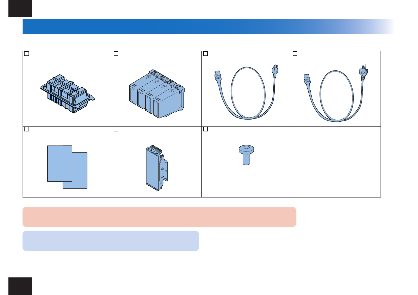
Checking the Included Parts
[1] 1 x Printhead Unit [2] 4 x Ink Tank (1 Ink Tank for each color) [3] 1 x Power Cord(for 120V series) [4] 1 x Power Cord(for 230V series)
[5] Spare Paper [6] 1 x Service Tool Unit [7] 1 x Screw
CAUTION:
Several types of Power Cords come with Printer. Use appropriate Power Cord for the power supply used at the installation site.
NOTE:
Included Spare Paper can be used for a print image checking.
Check that none of the following is missing:
• Start Guide
T-1-1
5
5
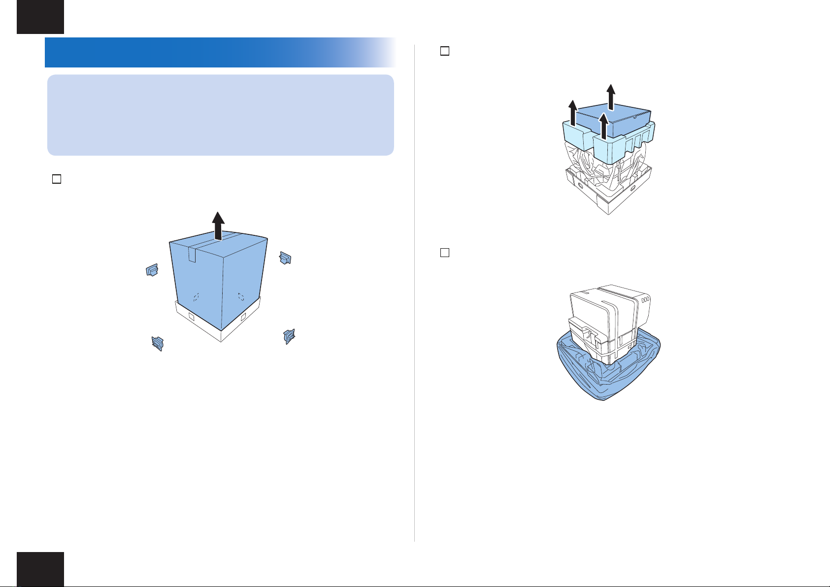
Unpacking Procedure
NOTE:
Printer is secured using xing tape and cushioning materials to protect it against
the vibrations and shocks applied during transportation. By following the procedure
described below, remove all pieces of xing tape and cushioning materials before
installing Printer. Keep the removed cushioning materials for future transportation for
relocation or repair of Printer.
1) Remove 4 grips from the packing carton, and then remove the outer casing.
F-1-3
2) Remove Accessory Box , and then remove Upper Pads.
3) Strip the plastic bag from top to bottom.
F-1-4
F-1-5
6
6
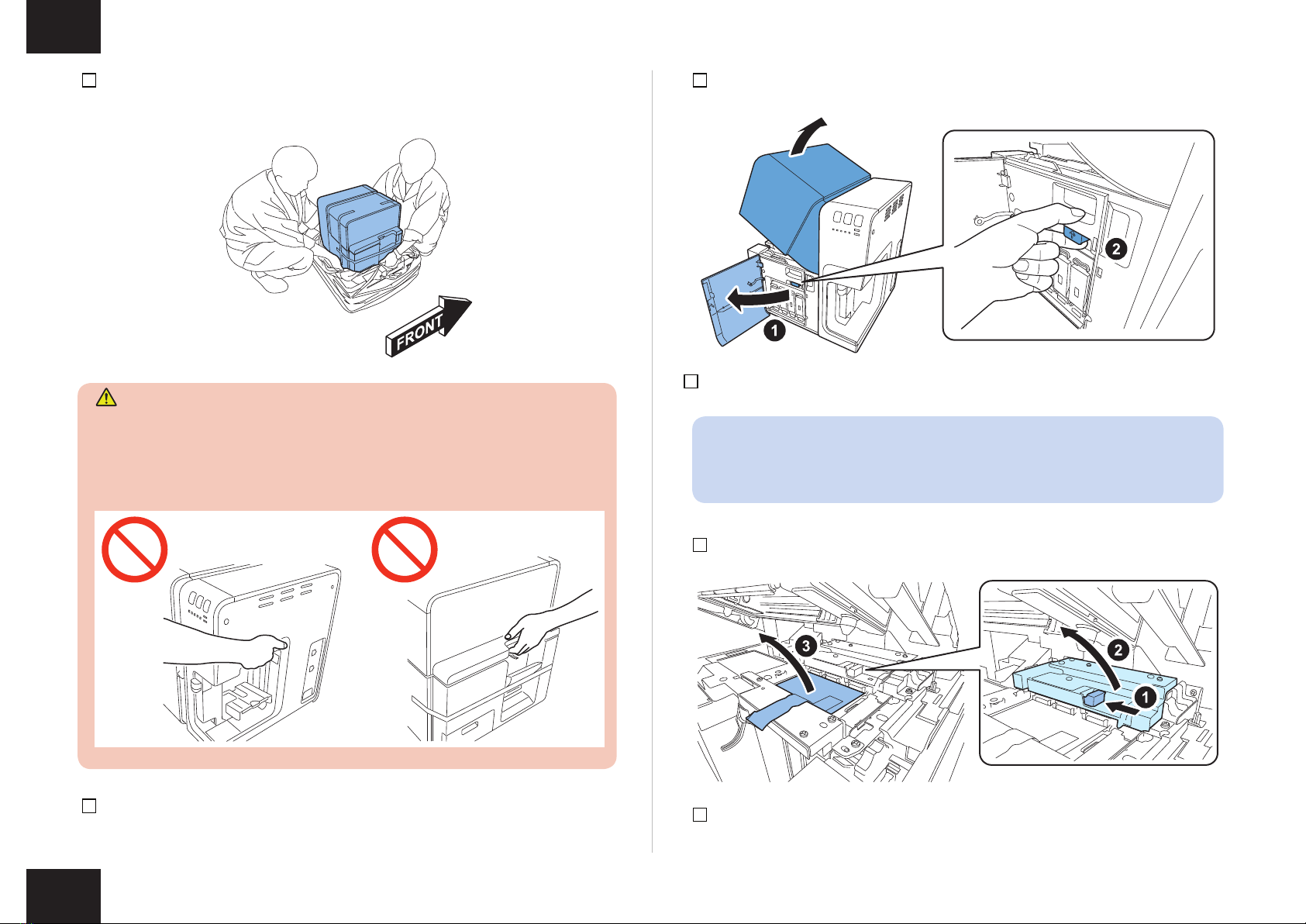
4) Holding the handles at the bottom of Printer, lift Printer to take it out from the package
base.
CAUTION:
• Printer weights about 25Kg. At least, two persons are required to lift it up.
• Do not lift Printer holding the paper feed section and paper delivery section to prevent
Printer from dropping as those sections may break. Dropping of Printer may cause
injury.
F-1-7
5) Place Printer on a horizontal table, and then remove all pieces of xing tape and
cushioning materials visible on the exterior of Printer.
F-1-6
6) Open Ink Tank Door, and open Upper Unit while holding Upper Unit Open Lever.
7) Remove xing tapes and cushioning materials from inside of Printer.
NOTE:
Keep the removed cushioning materials, because they may be used for future
transportation for relocation or repair of Printer.
8) Open Pinch Roller Unit, and then remove the protection sheet.
9) Close Pinch Roller Unit.
F-1-8
F-1-9
7
7
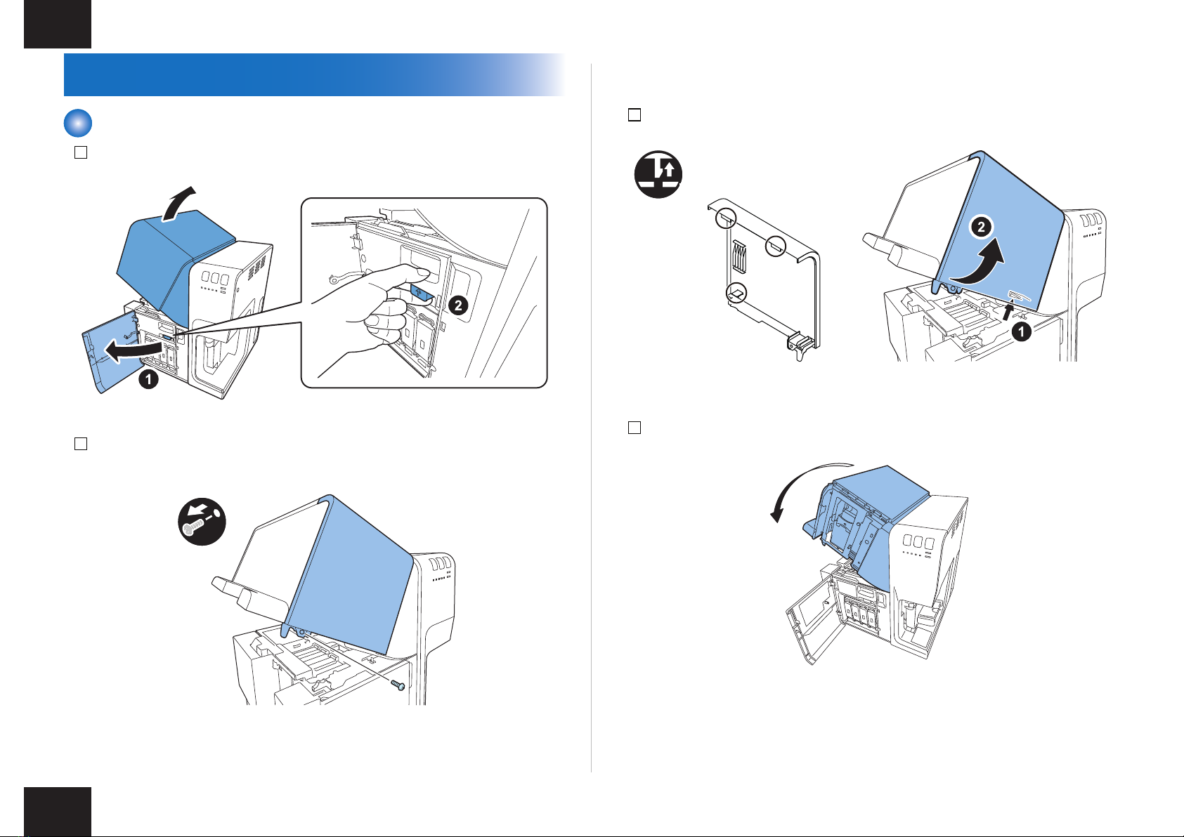
Installation Procedure
Mounting Printhead Unit
1) Open Ink Tank Door, and open Upper Unit while holding Upper Unit Open Lever.
2) Remove screw securing Maintenance Cover.
• 1 screw
F-1-10
F-1-11
3) Raise the inner hook to detach Maintenance Cover.
x3
4) Close Upper Unit.
F-1-12
F-1-13

8
8
5) Remove the xing tape, remove Print Module Cover, and then open Lower Printhead
Release Lever.
x4
F-1-14
F-1-15
6) Remove Blade Cleaner.
7) Take out included Printhead from the package.
F-1-16
F-1-17
9
9
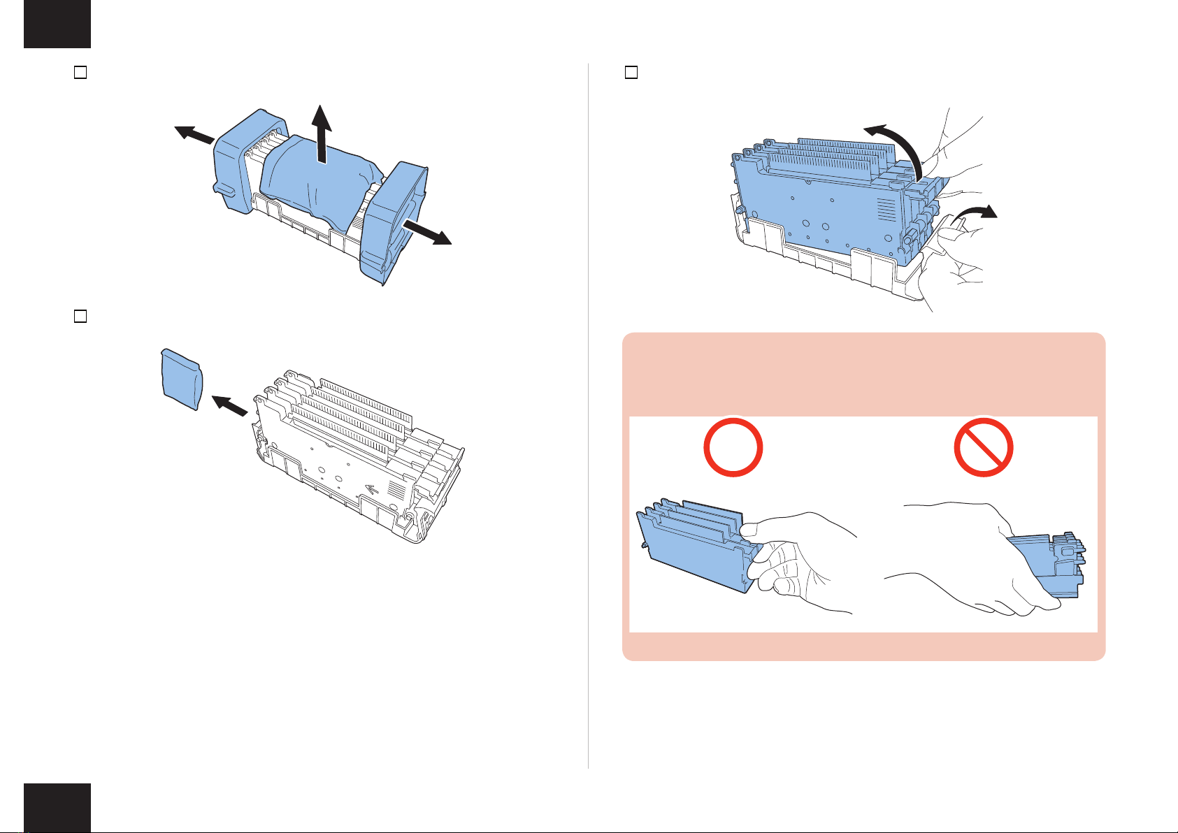
8) Remove the cover and cushioning materials.
9) Remove the 4 caps.
F-1-18
F-1-19
10) Take Printhead Unit out of the case.
CAUTION:
Do not touch the circuit boards and Printhead face. An ink injection problem can
occur.
F-1-21
F-1-20

10
10
11) Put Printhead Unit on the rail guide, and then insert it into Printer until it stops.
NOTE:
Skewering Shaft must be on Printhead Guide Rails.
CAUTION:
• To conrm Printhead Unit is in the correct position, see if the end of Printhead Unit
grip and the edge of the inner metal plate are in the same plane as shown in the
gure.
• If Printhead Unit is insufciently inserted, Lower Printhead Release Lever cannot
be closed.
F-1-23
F-1-22
12) Mount Blade Cleaner.
13) Close Lower Printhead Release Lever and Upper Printhead Release Lever.
F-1-24
F-1-25
Other manuals for SCC-4000D
3
Table of contents
Other SwiftColor Printer manuals

SwiftColor
SwiftColor SCC-2000D Assembly instructions

SwiftColor
SwiftColor SCC-2000D User manual

SwiftColor
SwiftColor SCL-2000P User manual

SwiftColor
SwiftColor SCL-4000D User manual

SwiftColor
SwiftColor SCC-4000D Guide

SwiftColor
SwiftColor SCL-4000D Guide

SwiftColor
SwiftColor SCC-2000D User manual

SwiftColor
SwiftColor SCL-8000P User manual


