10 / 16 | PP-105_201608 | FGS
Introduction
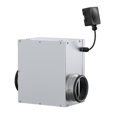
The instructions for the installation, operation and control refer
to the products of Systemair - the re air grille intended for
ventilation openings in walls without ductwork.
This manual contains basic information and recommendations
regarding the installation, use and inspections that need to be
followed to ensure the proper and smooth operation of the FGS.
The Systemair FGS is passive in terms of the amount of noise
generated. There is increased noise only when closing or opening
the FGS in cases of inspection or re accidents (only lasting for a
maximum of 60 seconds).
Warnings
Some FGS parts can have sharp edges – therefore it is necessary
to use gloves during FGS installation and manipulation.
In order to prevent an electrical injury, re or any other damage
which could result from incorrect FGS manipulation, installation,
usage and operation, it is important to:
1. Install the FGS in accordance with this installation manual and
by a properly trained employee.
2. Execute FGS inspection in accordance with this installation,
operation and maintenance manual.
3. Before you can install the FGS, it‘s functionality must be
checked according to Chapter 3 (“Functionality check“).
This procedure prevents the installation of an FGS that has been
damaged during transport or handling.
DO NOT INSTALL A NON-FUNCTIONING FGS!
Operating conditions
• Maximum air ow velocity 12 m/s (ventilation openings
in the wall without ductwork)
• Temperature within the range -20 °C up to +50 °C
• The active re-proof sealing must not be exposed to direct
contact with water.
• Purging air is only allowed without mechanical or chemical
contamination, with a uniform ow and without condensation,
ice coating or ice.
• FGS grilles are designed to be used in vertical supporting
constructions.
The device closes when the ambient temperature reaches
74 °C (manual FGS) or 72 °C (motorised FGS). In the event of
having to adjust for higher temperatures in the workplace, it
is necessary to consult such demands with the producer and
indicate them in the purchase order accordingly.
1 Installation
The installation must be done as follows:
• The FGS must not bear any part of the supporting construction.
This could lead to damage and the subsequent failure of the FGS.
• The distance between the FGS and building structures,
distribution technology and ventilation equipment must be
large enough for the reliable performance of the installation,
functional testing, inspection and repair.
• The distance between the FGSs must be at least 200 mm
in a solid wall according to EN 1634-1.
• The distance between the FGS and the wall must be at least
250 mm according to EN 1634-1.
• The FGS must be installed along the horizontal blade axis.
• Before the installation of the FGS, its functionality must be
tested according to Chapter 3 (“Functionality check“).
DO NOT INSTALL A NON-FUNCTIONING FGS!
• Changes to the functionality of the FGS, caused by transport
or installation, aren´t reclaimable after the installation
(deformations, damages, mechanical damage of the sealing
material, foreign objects which can constrain the blades,
improper handling of the activating mechanism, etc.)
• During installation it is necessary to protect the FGS mechanism
and its interior against dirt. The blades must be in the closed
position. This is necessary to avoid the deformation of the FGS.
• The FGS must be installed according to Fig. 2 or 3.
• After installing the FGS, it is necessary to connect the electrical
installation which must be only done by authorised persons -
the connection must be done according to Fig. 4 - 8.
• The actuators have two microswitches indicating the open and
closed positions of the blade - see Fig. 5 - 8.
• The setup, install, repair, overhaul and inspections of the FGS
must only be done by trained personnel.
1.1 WET installation of the FGS into a solid wall using a plaster
mixture, mortar or concrete (Fig. 2, Tab. 2)
1. Prepare a rectangular opening with dimensions
L1= L + 260 mm and H1= H + 135 mm (according to Fig. 1),
the opening surfaces must be even and cleaned.
2. Put together the frame from two parts (1a a 1b) according to
the wall width, and screw it into place with screws DIN 7982
C-H 4.2 × 13 included in the pack.
3. Fix the frame to the rectangular opening with screws
(recommended screws 5 × 100, fabory 29385.050.100,
screws not included in pack) Fig. 2. Part 1a of frame has to
be abreast with the wall. Lead the cable for the connect
- see Fig. 10 and 11.
4. Fill the space between the frame and the rectangular opening
with the plaster mixture, mortar or concrete (Fig. 2).
5. Connect the connector with the plug.
6. Insert the closed FGS into the installation frame, join the
connectors and x both the upper and lower sides of the FGS
with screws DIN 7504M-SR 4.2 × 25 (Pos. 6; screws are in
the pack - the amount depends on nominal dimensions of
the FGS)
7. If needed, uncover and clean the FGS after installation.
8. Check the functionality of the FGS.
Before putting the FGS into service after installation (and
in subsequent periodic inspections) a visual inspection and
functionality test must be conducted. After the visual inspection
and functionality test the results must be recorded in the
Operating log (page 13).
