manuals.online logo
Brands
  1. Home
  2. •
  3. Brands
  4. •
  5. System Sensor
  6. •
  7. Control Unit
  8. •
  9. System Sensor M902M User manual

System Sensor M902M User manual


M902M输入῵ഫ
ᅝ㺙ǃ㓈ᡸঞՓ⫼䇈ᯢк
Փ⫼乏ⶹ
ҹϟ䇈ᯢৃ԰Ўㅔ㽕ⱘՓ⫼ᣛᇐˈ㗠῵ഫⱘᅝ㺙᠟
ݠ᳝䆺㒚ⱘՓ⫼䇈ᯢৃկখ㗗DŽ؛བ䖭ѯ῵ഫᇚ㹿ᅝ㺙೼Ꮖᓔ䗮䖤㸠ⱘ㋏㒳䞠ˈ
䇋ࡵᖙ䗮ⶹ⫼᠋ঞ᳝݇ᡔᴃҎ䅽㋏㒳᱖ᯊ݇䯁ˈֱ䆕ᅝ㺙䖭ѯ῵ഫᯊˈ᥻ࠊ఼ϡᏺ⬉⑤DŽ
⊼ᛣ˖ℸ῵ഫⱘՓ⫼㗙ᑨֱ⬭ᴀ䇈ᯢкDŽ
⊼ᛣ˖ℸ῵ഫⱘՓ⫼㗙ᑨֱ⬭ᴀ䇈ᯢкDŽ
ὖ䗄
M902M输入模块仅允许与智能型控制器接口并监视两线制传统型探测器。
ᔧ输入῵ഫ໘Ѣ䗮䆃⢊ᗕᯊˈᅗৃᇚϸ㒓ࠊ᥶⌟఼ⱘ⢊ᗕӴ䗕ࠄᱎ㛑᥻ࠊ఼ˈ᡹ߎ䋳䕑⬉䏃ᰃℷᐌǃᓔ䏃៪᡹䄺⢊ᗕDŽ
本῵ഫഄഔՓ⫼⬉ᄤ㓪ⷕ఼&30೼11至1П䯈䆒ᅮDŽ᠔ᦤկⱘ/('ᣛ⼎♃⬅᥻ࠊ఼থߎⱘҸⷕᴹ᥻ࠊ(见图1)DŽ
ᡔᴃᴵӊ


图1ǃ输入῵ഫ指示灯示意图:

输入⢊ᗕᣛ⼎♃


ϢM902M῵ഫⳌݐᆍⱘϸ㒓ࠊ᥶⌟఼
:
图3、M902M
输入῵ഫϢB401/B801底座配置接法:



第2页共2页 I56-1902-02C












ৃ䗝ᢽⱘಲ䏃ߚᬃ
এϟϔ᥹ষ῵ഫ
῵ഫⲥ㾚᠔կ⬉᥶⌟఼ಲ䏃
ᥝ⬉ᠡ㛑Փ᥶⌟఼໡ԡˈ᥼㤤Փ
⫼ৃ໡ԡ9ˈ㢹᮴ˈ߭᠔կ⬉⑤
ৃ䗮䖛᥻ࠊ῵ഫ䖯㸠ᮁ⬉ߛ换。

῵ഫা㛑Ϣݐᆍⱘ᥻ࠊ఼
䜡༫Փ⫼
ϸ㒓ࠊӴ㒳᥶⌟఼߱ྟಲ䏃䆒໛˄,'&˅1)3$%
᳔໻ࡳ⥛˖PAˈ9'&
Ϣ䆒໛䯈䖲㒓ϡ䍙䖛¡៪᥹㒓῾៾䴶ϡ䍙䖛
PP

ৠϔ῵ഫϡ㛑ݐ᳝᡹䄺ǃ㘨ࡼঞⲥ㾚ᅝܼ䆒໛

ಲ䏃ᘏ㒓
᳔໻9'&
ϡ㽕ᇚ⦃㒓᥹ܹッᄤˈ䇋ᇚ㒓࠾ᮁ᥹ܹҹ֓ⲥ㾚䖲
᥹ᚙމDŽ
ᇍѢϢ῵ഫⳌݐᆍⱘ᥶⌟఼ⱘᅝ㺙ˈ䇋ᣝࠊ䗴ଚ
䇈ᯢ䖯㸠。
ⱘࡳ㛑。
᠔⼎䖲㒓ഛফࡳ⥛䰤ࠊ
ಲ䏃ᘏ㒓
এϟ
ϔ
ԡ
输入模块
B401/%801底座
18-29VDC
3.9K
终端电阻
探测器信号线
电源总线
1
2
3
4
5
6
䋼䞣ֱ䆕


西安盛赛尔电子有限公司ᇍ᠔⫳ѻⱘѻકᅲ㸠ϝᑈֱׂDŽ如果是由于人为损坏、使用不当或自行调整改动产品而导致
失效的产品,不属于本保修范围,而因此造成的后果西安盛赛尔电子有限公司将不负责任。
第1页共2页 I56-1902-02C





᥶⌟᳔఼໮᭄䞣


㽓ᅝ催ᮄᡔᴃᓔথಶ㒧䏃ো
Ё೑䰩㽓㽓ᅝ䚂㓪˖
⬉䆱5387800Ӵⳳ332959




ᅝ㺙
M902M
ৃⳈ᥹㺙ܹ
50mm
⏅
, 100mm
㾕ᮍⱘ乘ඟⲦݙDŽ
䖲㒓
⊼ᛣ˖᠔᳝ⱘ䖲᥹㒓ᖙ乏⒵䎇ᔧഄⱘ⊩ᕟǃ⊩㾘ঞ᳝݇ᴵ՟ⱘ㽕
∖DŽᔧ೼≵᳝ࡳ⥛䰤ࠊⱘഎড়Փ⫼᥻ࠊ῵ഫᯊˈᖙ乏Փ⫼
CB500
ൟ䱨ᶊˈҹ⒵䎇᳝݇ⱘ㽕∖Փ᳝ࡳ⥛䰤ࠊҹঞ≵᳝ࡳ
⥛䰤ࠊⱘッᄤঞ䖲㒓ⲦߚᓔDŽ
CB500
ൟ䱨ᶊᖙ乏㕂 ܹ
100mm
㾕ᮍˈ⏅
50mm
ⱘ乘ඟⲦݙˈ᥻ࠊ῵ഫᖙ乏ᬒܹ䱨
ᶊˈᑊϔ䍋ᬒܹ乘ඟⲦ˄㾕೒
2A
˅DŽ᳝ࡳ⥛䰤ࠊⱘ䖲㒓ᖙ乏
㕂ܹ䱨ᶊⱘ᠛ᔶߚ䱨ᄨݙ˄㾕೒
2A
˅DŽ
ǃ῵ഫⱘ᥹㒓ᖙ乏ᣝ✻䆒䅵೒㒌೒
3
ⱘ᥹㒓᠔⼎DŽ
2
ǃᣝ೒㒌䆒㕂῵ഫഄഔDŽ
3
ǃᣝ೒
2
A
ˈᇚ῵ഫ೎ᅮ೼乘ඟⲦݙ˄⬅ᅝ㺙㗙ᦤկ˅DŽ

执行标准:GB16806-2006 认证标志:
)
ݐᆍᗻ㽕∖

Ўњ⹂ֱ㋏㒳ℷᐌᎹ԰ˈℸ῵ഫҙϢݐᆍⱘ᥻ࠊ఼䜡༫Փ⫼DŽ
ᦤկ㒭M902Mⱘ໪䚼9'&⬉⑤㽕∖ᰃৃ໡ԡⱘ9'&⬉⑤DŽ
ࣙ㺙ݙᆍ
输入῵ഫࣙᣀҹϟݙᆍ˖
˄
1
˅ϸ㒓ࠊ输入῵ഫ˗
˄
2
˅
3.9K
󱂜ྚⱘ㒜ッ⬉䰏˗
˄
3
˅ⱑ㡆Ⲫᵓ˗
˄
4
˅Ⲫᵓ᠔⫼ⱘ㶎䩝
图2B、模块与预埋盒及面板安装外形尺寸示意图:
图2A、模块与与隔架的安装:
124.6mmmm
62mmmm
124.6mmmm
探测器型号 探测器类型 底座型号 探测器最多数量
JTY-LZ-881 离子 DZ-B801 25
JTY-GD-882光电 DZ-B801 25
JTW-SD-885 感温 DZ-B801 25
光电 DZ-B401/B 20
JTY-LZ-1451 离子 DZ-B401/B 20
JTW-BCD-5451 感温 DZ-B401/B 20
JTY-LZ-1151 离子 DZ-B401 20
JTY-GD-2151 光电 DZ-B401 20
JTY-GD-2451
初始回路设备(IDC)- 端子5、6
电流
IDC 回路电阻
静态电流
配接探测器电流
报警电流
类型
终端电阻
最大102mA
最大25Ω
最大12mA @最大IDC 电压
最大2.4mA
最小18 mA
B型(class B)
3.9K 欧姆
温度
湿度
重量
外形尺寸
辅助器件
通讯线 - 端子1、2
电压
电流
回路电阻
外部所供电源要求-端子3、4
电压
纹波
电流
-10℃至 55℃(14℉-131℉)
5%-95%RH,无凝结
92g (0.2 lbs)
124.6mm长x124.6mm宽x62mm高
(模块与预埋盒及面板安装尺寸,见图2B)
SMB500/W 900系列模块预埋盒
15-32VDC
最大800μA@ 24VDC,不通讯时.
最大 1.8 mA 24V (红灯锁定)
最大40Ω
18-29 VDC(滤波、整形以及功率限制)
最大 100mV RMS
102mA/模块
断电才能使模块复位。为了使系统正常工作,端子3、4上的接口模块
电压不能低于18VDC。短路故障检核须由控制器来完成。
终端电阻是使每一区域的探测器回路有足够的回
路电流,通过对回路电流的监控,来监视探测器回路
的连线及探测器的安装状态。当断线或探测器脱落
时,导致终端电阻被断开,回路电流小于额定值时,
模块报断线故障。
软件版本: A
ѻક󰵼ㅒ᮹ᳳⷕᵘ៤䇈ᯢ
ѻકⱘ᮹ᳳⷕ⬅ಯԡ᭄㒘៤˖㄀ϔԡ㸼⼎⫳ѻᑈӑⱘ᳿ԡ᭄ᄫ˗㄀Ѡԡ㄀
ϝԡ㸼⼎⫳ѻⱘ᳜ӑ˗㄀ಯԡ㸼⼎ᔧ月第几周。
X X X X
㸼⼎˖Ā⫳ѻᑈⱘ᳿ԡ᭄āĀ⫳ѻ᳜ӑāĀ当᳜㄀޴ā
INSTALLATION AND MAINTENANCE INSTRUCTIONS
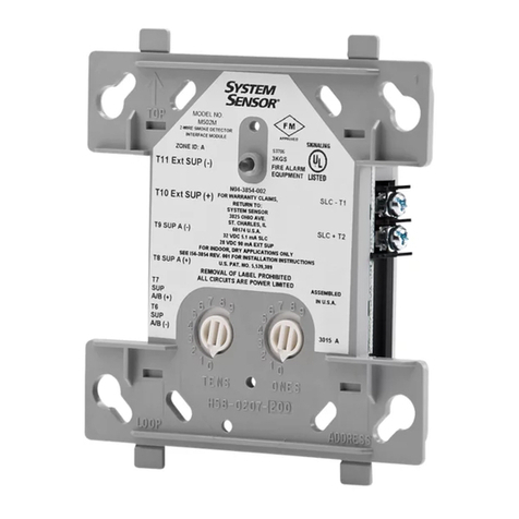
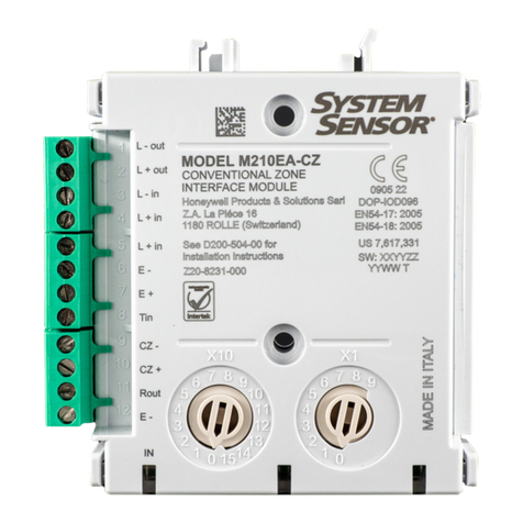
M902M Input Module
For Two-wire Conventional Detector
Before Installing
This information is included as a quick reference installation guide. Refer to the appropriate installation manual for detailed system information. If
the modules will be installed in an existing operational system, inform the operator and local authority that the system will be temporarily out of
service. Disconnect power to the control panel before installing the modules.
NOTICE: This manual should be left with the owner/user of this equipment.
General Description
The M902M Input Module allows intelligent panels to interface and monitor two-wire conventional smoke detectors.
The module address should be set by the model CP900M from 101to 199. When the module is interrogated, it transmits the status of one zone of
two-wire detectors to an intelligent control panel. Status conditions are reported as normal, open, or alarm.
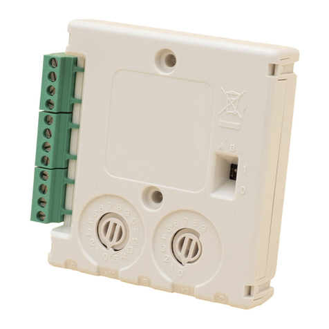
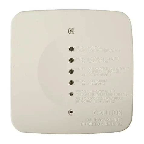
A status LED indicator is provided and is controlled by code command from the control panel. (
See Figure 1
).
Specifications
Compatibility Requirements
To insure proper operation, this module shall be connected to
compatible intelligent control panels only. Conventional two-wire
smoke detectors must be compatible with the interface module. The
external power 24VDC which supplies the power to the detector must be
reset.
Package Contents
The input module includes the following items:
(1) Two-wire interface module
(1) 3.9K ohm end-of-line resistor
(1) Off-white cover plate
(1) Screw pack for cover plate
Wiring
NOTE: All wiring must conform to applicable local codes, ordinances
and regulations. When using control modules in nonpower limited
applications, the CB500 Module Barrier must be used to meet the
requirements for the separation of power limited and nonpower-limited
terminals and wiring. The barrier must be inserted in a 100mmsquare by 50mm
deep electrical boxes, and the control module must be placed into the
barrier and attached to the junction box (Figure 2A). The power-limited
wiring must be placed into the isolated quadrant of the module barrie.
Mounting
The M902M Input Module mounts directly to 100mm square electrical
boxes as shown in
Figure 2
A.The box must have a minimum depth of
50mm.
1. Install module wiring in accordance with the job drawings and
appropriate wiring diagrams (Figure 3.).
2. Set the address on the module per job drawings.
Figure 1. Input Module and Indicator
detailing Mounting Arrangement
Temperature: -10° C to 55° C (14°F to 131° F) External Power Supply Requirements-Terminals 3 & 4
Humidity: 5% to95%RH Noncondensing Voltage:18 to 29 VDC (filtered, regulated, and power-limited)
Weight: 0.2bs (92 g) Ripple: 100mV RMS Max
124.6mm L x 124.6mm W x62mm H (with the
mountingplate andthe junctionbox, seeFigure 2B ) Current:102 mA per module
Accessories: SMB500/W Surface Mount Box for 900 series
modules
(Power must be interrupted to reset detectors. The interface module
must have a minimum of 18 VDC at terminals 3 and 4 to function
properly. Ground fault detection must be accomplished by the
control panel.)
Communication Line-Terminals 1 & 2
Voltage: 15 – 32 VDC Loop Impedance: 40¡Max
Current: 850µA Max @ 24 VDC, no communication
1.8 mA Max 24V (LED latched on)
Initiating Device Circuit (IDC) – Terminals 5 & 6
Current: 102 mA Max Detector Current in Standby: Up to 2.4 mA
Standby Current: 12 mA Max @ maximum IDC voltage Style: Style B (class B)
IDC Loop Impedance: 25¡Max EOL Resistance: 3.9K ohm nominal
Alarm Current: 18 mA minimum
(Detector loop current is sufficient to ensure operation of one alarmed detector per zone.)
1of 2 I56-1902-02C

Figure 3. M902M Input Module Wiring Diagrams
with B401/B801 Base:
2 of 2 I56-1902-02C
Ver.D
CONNECT MODULES TO LISTED
COMPATIBLE CONTROL
PANELS ONLY.
FROM PANEL OR
TERMINAL WIRING MUST BE
POWER LIMITED
IS RECOMMENDED
COMMUNICATION LINE
32 VDC MAX
TWISTED PAIR
RESISTOR
(INCLUDED)
DO NOT LOOP WIRE UNDER TERMINALS BREAK WIRE
RUN TO PROVIDE SUPERVISION OF CONNECTIONS.
DETECTORS MUST BE UL LISTED COMPATIBLE WITH
MODULE.
INSTALL DETECTORS PER MANUFACTURE’S
INSTALLATION INSTRUCTIONS.
OPTIONAL BRANCH CIRCUIT
TO NEXT INTERFACE MODULE
MODULE SUPERVISED SUPPLY
VOLTAGE AND DETECTOR LOOP.
POWER TO THE INTERFACE MODULE
MUST BE EXTERNALLY SWITCHED TO
RESET THE DETECTORS. A CONTROL CMX-7
MODULE CAN BE USSED TO SWITCH
POWER FROM A STANDARD POWER
SUPPLY.
18-29 VDC
BB401/B801 Base1 Base
2-WIRE CONVENTIONAL DETECTOR
INITIATING DEVICE CIRCUIT (IDC)-NFPA STYLE B
POWER LIMITED 102mA MAX:29VDC MAX
IDC INSTALLATION WIRING MUST NOT EXCEED
25 OHMS, 12-18AWG
DO NOT MIX FIRE ALARM INITIATING SUPERVISORY.
OR SECURITY DEVICES ON THE SAME MODULE
3.9k EOL
TO NEXT
DEVICE
PREVIOUS DEVICE
1
4
3
2
6
5
Three-Year Limited Warranty
Xi'an System Sensor warrants its enclosed products to be free from defects in materials and workmanship under normal use and service for a period
of three years from date of manufacture. The company’s obligation of this Warranty shall be limited to the repair or replacement of any art of the
product, which is found to be defective in materials or workmanship under normal use and service during the three year period commencing with the
date of manufacture.
The Company shall not be obligated to repair or replace units which are found to be defective because of damage, unreasonable use, modifications,
or alterations occurring after the date of manufacture.
Compatible Two-wire System Sensor Smoke Detectors for Use with M902M : A
3. Secure module to electrical box (supplied by installer), as shown in Figure 2A.
Standard: GB16806-2006 Certification:
)
Figure2A. Exploded View of Typical Module
124.6mm
124.6mmmm
62mmmm
Figure2B. Module Mounting Size:
LED Status
Dimensions:
Detector
Model Detector
TypeBase
Model Max
Detector
JTY-LZ-881 Ionization DZ-B801 25
JTY-GD-882 Photoelectric DZ-B801 25
JTW-SD-885 Thermal DZ-B801 25
JTY-GD-2451 Photoelectric DZ-B401/B 20
JTY-LZ-1451 Ionization DZ-B401/B 20
JTW-BCD-5451 Thermal DZ-B401/B 20
JTY-LZ-1151 Ionization DZ-B401 20
JTY-GD-2151 Photoelectric DZ-B401 20
Software Ver. A
Product Nameplate Date Code Note:
XX X X
Stands for: The end number of the producing year the producing month the week of the month
Other System Sensor Control Unit manuals

System Sensor MDl Series User manual

System Sensor

System Sensor MDl Series User manual

System Sensor M500FP User manual

System Sensor

System Sensor M500FP User manual

System Sensor SC-6 User manual

System Sensor

System Sensor SC-6 User manual

System Sensor SC-6 User manual

System Sensor

System Sensor SC-6 User manual

System Sensor MDL3 Series User manual

System Sensor

System Sensor MDL3 Series User manual

System Sensor EM-1SRI User manual

System Sensor

System Sensor EM-1SRI User manual

System Sensor MDL3W User manual

System Sensor

System Sensor MDL3W User manual

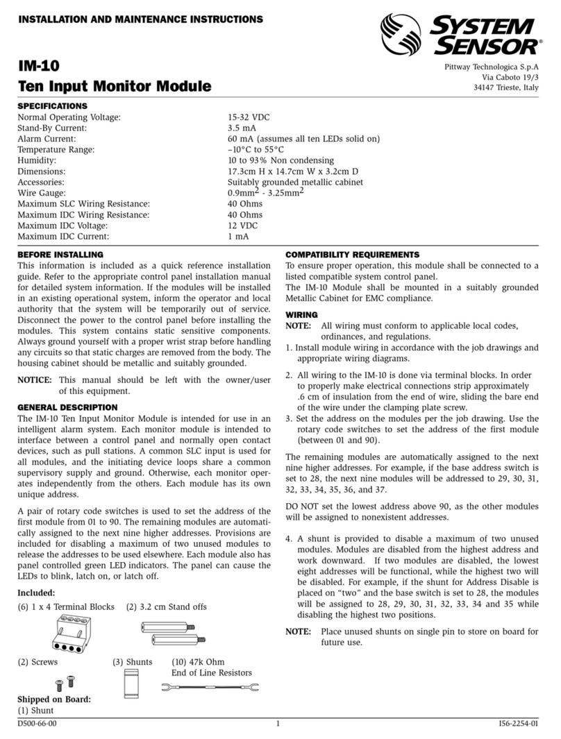
System Sensor IM-10 User manual

System Sensor

System Sensor IM-10 User manual

System Sensor Supervised Control Module M500S User manual

System Sensor

System Sensor Supervised Control Module M500S User manual

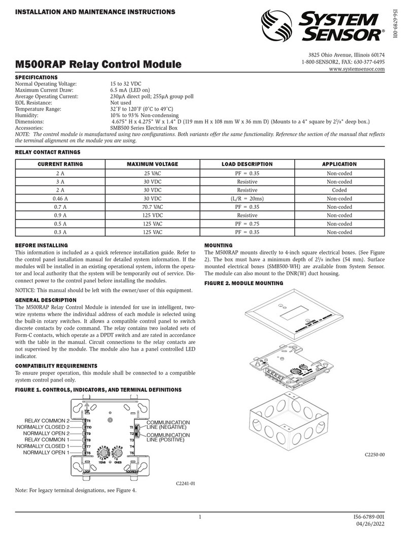
System Sensor M500RAP User manual

System Sensor

System Sensor M500RAP User manual

System Sensor I4 Series User manual

System Sensor

System Sensor I4 Series User manual

System Sensor M500M User manual

System Sensor

System Sensor M500M User manual

System Sensor IM-10 User manual

System Sensor

System Sensor IM-10 User manual

System Sensor M502MA User manual

System Sensor

System Sensor M502MA User manual

System Sensor M500M User manual

System Sensor

System Sensor M500M User manual

System Sensor M502M User manual

System Sensor

System Sensor M502M User manual

System Sensor M500DMR User manual

System Sensor

System Sensor M500DMR User manual

System Sensor M500SAP User manual

System Sensor

System Sensor M500SAP User manual

System Sensor SC-6 User manual

System Sensor

System Sensor SC-6 User manual

System Sensor M500M User manual

System Sensor

System Sensor M500M User manual

System Sensor i3 Series User manual

System Sensor

System Sensor i3 Series User manual

System Sensor M210EA-CZR User manual

System Sensor

System Sensor M210EA-CZR User manual

System Sensor SpectrAlert MDL User manual

System Sensor

System Sensor SpectrAlert MDL User manual

System Sensor M501MAP User manual

System Sensor

System Sensor M501MAP User manual

Popular Control Unit manuals by other brands

Sera 620.D operating instructions

Sera

Sera 620.D operating instructions

Hach Ultra MET ONE Operator's manual

Hach Ultra

Hach Ultra MET ONE Operator's manual

ESP Safety VECTOR Calibration guide

ESP Safety

ESP Safety VECTOR Calibration guide

Comelit 4682HD Technical manual

Comelit

Comelit 4682HD Technical manual

Lenze E82ZAFCC210 Mounting instructions

Lenze

Lenze E82ZAFCC210 Mounting instructions

Siemens LME11 series manual

Siemens

Siemens LME11 series manual

Grundfos CIM 1 Series Installation and operating instructions

Grundfos

Grundfos CIM 1 Series Installation and operating instructions

VAT 61228-KAGG-0002 Installation, operating,  & maintenance instructions

VAT

VAT 61228-KAGG-0002 Installation, operating, & maintenance instructions

Enterasys VH-SMGMT Quick installation guide

Enterasys

Enterasys VH-SMGMT Quick installation guide

ascon TRH03 Engineering manual

ascon

ascon TRH03 Engineering manual

Hydac FCU 1310 Operating and maintenance instructions

Hydac

Hydac FCU 1310 Operating and maintenance instructions

Anybus CompactCom reference guide

Anybus

Anybus CompactCom reference guide

aquabrass 1004 Installation procedures

aquabrass

aquabrass 1004 Installation procedures

MKS HPS Service manual

MKS

MKS HPS Service manual

IFM Electronic Ecomat 300 AL1030 Device manual

IFM Electronic

IFM Electronic Ecomat 300 AL1030 Device manual

Kaysun KCCT-64 IPS Installation and operation instructions

Kaysun

Kaysun KCCT-64 IPS Installation and operation instructions

Zte ME3000 user manual

Zte

Zte ME3000 user manual

ELMEKO ST-USB operating instructions

ELMEKO

ELMEKO ST-USB operating instructions

manuals.online logo
manuals.online logoBrands
  • About & Mission
  • Contact us
  • Privacy Policy
  • Terms and Conditions

Copyright 2025 Manuals.Online. All Rights Reserved.