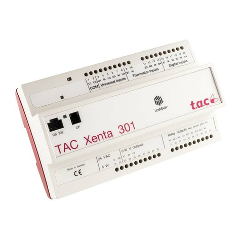
t.a.c. MZ18L User manual

1 (8) 0-003-1902-0 (GB)
MZ18L G-50-30
Actuator Zone 1999-11-29
Subject to modification.
TECHNICAL DATA
The LON actuator is targeted for decentralized building
structures and gives customers an effective new
capability in energy management and product flexibility.
The actuator works with standard SNVTs to provide
interoperability with controllers based on LonWorks
technology.
The MZ18L small linear actuator is specifically designed
to provide LonMark capabilities together with valve
series VZ22, VZ32, VZ42 and are used in fan coil units,
Item no .................................................................. 845-5102
Power supply .............................. 24 VAC, ± 20%, 50/60 Hz
Power consumption ................................................... 1,4 VA
Control signal .......................... SNVT_lev_percent 0–100%
Network protocol...................................................... LonTalk
Channel ................................................................... FTT10A
Stroke ....................................................................... 6,5 mm
Running time ................................................ 150 s at 50 Hz
.................................................................. 120 s at 60 Hz
Stem force .............................. 180 N (for valves DN 15–20)
Protection standard ..................................................... IP 42
Insulation class .................................................................. III
Connection cables ................................... 1,5 m, three leads
............................................................... 1,5 m, two leads
Coupling ring ....................................................... M 30 x 1,5
Ambient operating temperature limits..................0 – +55 °C
Weight ........................................................................ 0,4 kg
Suitable for valves ................................ see table, last page
58
60
80
49
induction units, small reheaters, recoolers and for zone
control applications.
The MZ18L actuator is suitable for controllers based on
LonWorks technology. Using standard Echelon
configuration tools, the actuator can be configured with
job specific settings.
ECHELON®, LON®, LONWORKS®, LONTALK®NEURON®, LONMARK®LOGO are registered Trade
marks of Echelon Corporation, USA.

2 (8)0-003-1902-0 (GB)
FUNCTION
The movement of the electric actuator
is produced by a screw spindle which is
driven in both directions by a
synchronous motor through a set of
gears. A magnetic clutch limits the
torque of the gear assembly and the
driving force of the actuator.
The actuator is fixed to the valve body
by means of a coupling ring requiring
no tools for mounting.
The actuator is maintenance-free and
supplied completely with a ready-to-
wire connecting cable.
Fig. 1
11.7 mm
17.8 mm
MMI DESCRIPTION
Service LED: Defined by Echelon firmware in the neuron
chip (see table 1)
Status LED: Is blinking if wink was sent and indicates
reverse or direct acting (see table 2 and
diagram 1)
Service PIN: Accessible under the cover and will be
used to send the neuron ID over the
network during the installation.
Mode 1
12345678910 n Time [s]
Mode 2
12345678910 n Time [s]
Mode 3
on
off
12345678910 n Time [s]
Mode 4
12345678910 n Time [s]
Reverse
Direct
on
off
on
off
on
off
Node state hF01F Service Pulse rate
Service LED Status LED (Hz)
code
Applicationless and 3 on 76
unconfigured
Unconfigured 2 Flashing 0.51
(but with an
application)
Configured, 6 off —
Hard Off-line
Configured 4 off —
Selecting valve type and output signal.
Diagram 1. Status LED
AB
AB
AAB
B
SERVICE LED
STATUS LED
SERVICE PIN
Fig. 2
Table 1. Service LED
Status LED Blink Modes
Mode 1 1 s on, 1 s off, for 10 times - if a
wink message was received
Mode 2 4 s on, 1 s off - direct acting and
normal operation
Mode 3 4 s off, 1 s on - reverse acting and
normal operation
Mode 4 continuously off - the device is in
the offline-mode
Table 2. Status LED
The movement of the actuator stem
(Fig. 1) indicates whether the valve is
opening or closing.
If the direction of travel is not correct,
the configuration parameter nciDirRev
(SNVT-state) can be used for changing
the direction of action.
A functional check of the valve actuator
can be carried out by changing the
nviManActPos (SNVT_lev_percent).

3 (8) 0-003-1902-0 (GB)
CONNECTIONS
The electrical installation must comply
with the wiring diagram shown in Fig. 5
and Fig. 6.
Fig. 6
LONMARK NETWORK INTERFACE
The Actuator with LON Capabilities will
support the following subset of the
SNVT variables used for the
communication and binding. The
detailed specification of the network
variables will be found in the LonMark
Objects Summary.
Disc with external interface files (.xif) for
MZ18L/MZ09L......... Art. no 0-008-5648
Fig. 7
Fig. 5
The actuator may only be mounted
beside or above the valve. Adjust the
valve in the right position before
mounting the actuator. (Fig. 3)
Before the actuator is fixed to the valve,
the adjustment cap must be removed.
Make sure that the actuator is in the
open position (factory supplied position)
before fixing the actuator to the valve
body. (Fig. 4)
The actuator must be mounted by hand.
Don’t use tools or additional forces,
because actuator and valve may be
damaged.
Fig. 4
Fig. 3
MOUNTING
Open Loop Actuator Object, Object Type 3
nviActPos
SNVT_lev_percent
nv1
nviManActPos
SNVT_lev_percent
nv2
nvoActPosFb
SNVT_lev_percent
nv3
nvoDISwitch
SNVT_switch
nv4
Mandatory
Network Variables
Optional
Network Variables
Optional
Configuration Properties
nciDefaultOutput
nciDIConfig
nciDirRev
nciRunTime
nciMaxRcvTime
Configuration Parameter
(SNVT_lev_percent)
(SNVT_lev_disc)
(SNVT_state)
(SNVT_time_sec)
(SNVT_time_sec)
Reset the device
after modifying
Configuration
Parameters
Power supply + DI
LON
Brown
White
Green
24 V AC+
24 V AC-
DI+
Black
White LON FTT10
LON FTT10 (C)
(C)
(G)
(G0)
MZ18L
Brown
White
Green
Black
White LON
24 VAC
DI

4 (8)0-003-1902-0 (GB)
DESCRIPTION OF USED SNVTS* AND SCPTS**
This table shows all used standard network variables and
standard configuration parameters, their default values, a
short description, the range and the send conditions and
service of the outputs.
Standard Network
Variable
Type
{Range}
{factory settings}
Adjustment of the different functionalities and the explanation of the shown values.
Definition Explanation
nviActPos SNVT_lev_percent
{0...100 % ; 163.835}
{163.835} = INVALID
nviActPos = 163.835 [INVALID]
After Power-on or Reset
Controller is sending [INVALID].
The actuator will run to the safety position
defined in [nciDefaultOutput].
Watchdog has “detected”;
Only possible if the watchdog was selected in
[nciMaxRcvTime] and will correspond on the
made selection in [nciDefaultOutput].
The actuator will run to the safety position
defined in [nciDefaultOutput].
nviActPos = 0% or 100%
Synchronization with full running time + 30%.
The synchronization can be interrupted if new
values are received.
(excluding during synchronization after Power-
on or Reset)
0% < nviActPos < 100%
The actuator runs to the position received by
the controller.
(Exceptional case is after Power-on or Reset)
The actuating signal received from a
controller defined in the range of 0-
100% which defines the stroke
position of the connected valve.
Received values below 0% are
calculated like 0% and values over
100% will be calculated with 100%.
The only exception is the value
163.835 = [INVALID]. Is this value
received, the actuator drives to the
safety position which is defined in the
[nciDefaultOutput].
The received values will be never
overwritten by the software of the
actuator.
The variable [nviActPos] is only be
used, if the variable with higher priority
[nviManActPos] for manual operation
is set to [INVALID] = 163.835.
The cyclic received actuating signal
can be supervised. In this case, the
maximum time frame for the cyclic
received values can be defined in the
configuration parameter
[nciMaxRcvTime].
Is this time frame passed, the actuator
will be running to the safety position
defined in the configuration parameter
[nciDefaultOutput].
Mandatory Network Variables
Definition Explanation
nvoActPosFb SNVT_lev_percent
{0...100 % ; 163.835}
{163.835} = INVALID
nvoActPosFb = 163.835 (INVALID)
After Power-on or Reset.
No defined stroke position feedback possible.
0% <= nvoActPosFb <= 100%
The actual calculated position of the stem
according to the time to stroke model.
This value shows the actual
calculated stem position
Optional Network Variables

5 (8) 0-003-1902-0 (GB)
nviManActPos SNVT_lev_percent
{0...100 % ; 163.835}
{163.835} = INVALID
nviManActPos = 163.835 (INVALID)
After Power-on or Reset
Manual operation is switched off
nviManActPos = 0% or 100%
Synchronization with full running time + 30%.
The synchronization can be interrupted if new
values are received.
(excluding during synchronization after Power-
on or Reset.
0% < nviManActPos < 100%
The actuator is running to the manual set value.
(Exceptional case is after Power-on or Reset)
The actuator can be operated manually.
To have most accuracy a
synchronization to the completely retract
position has to be done.
The watchdog [nciMaxRcvTime] is
operating in the background (if selected).
The manual operation has in each case
a higher priority than the received
actuating signal [nviActPos]. After
changing the value for manual operation
[nviManActPos] to [INVALID] the
actuator is running according to the
received values of [nviActPos].
Received values below 0% are
calculated like 0% and values over 100%
will be calculated with 100%. The only
exception is the value 163.835 =
[INVALID]. Is this value received, the
actuator drives to the safety position
which is defined in [nciDefaultOutput].
The received values are never
overwritten by the software of the
actuator.
Definition Explanation
Optional Network Variables
NvoDISwitch SNVT_switch
Possible values
{0.0 , 0 }
{100.0 , 1}
{x, 0xFF=255=-1)}
The possible conditions can be selected by the
configuration parameter [nciDIConfig].
A detailed description is made in the
Selection of Digital Input Usage
section. Actual state of the sensor,
connected to the digital input (e. g.
window-contact or dewpoint-sensor).
nciDirRev SCPT direction
Direct Mode of the Actuator
nviActPos = 0% (Stem retract)
nviActPos = 100% (Stem extract)
Status Led blinking : 4 s on / 1 s off
Reverse Mode of the Actuator
nviActPos = 0% (Stem extract)
nviActPos = 100% (Stem retract)
Status Led blinking : 1 s on / 4 s off
Inverse the direction of action
1111111111111111= Direct
0000000000000000= Reverse
Definition Explanation
Standard
Configuration
Parameters
Adjustment of the different functionalities and the explanation of the
shown values.
SCPT Master List -
Names from
Echelon
SNVT_state
{Bits = 1 or 0}
{1111111111111111}
Type
{Range}
{factory settings}
nciMaxRcvTime SCPTmaxRcvTime Is no value [nviActPos], in a certain time
frame [nciMaxRcvTime] received, the
actuator will run to the position defined in
[nciDefaultOutput].
This is called a heartbeat control or
watchdog function.
Watchdog for the Controller /
Actuator supervision
[nciMaxRcvTime] = 0
Watchdog is deactivated
[nciMaxRcvTime] =
for example 60 [sec]
Watchdog expires, if for 60
seconds no new value is
received on [nviActPos]. The
actuator will run to the position,
defined in the configuration
parameter [nciDefaultOutput].
SNVT_time_sec
{0...6553 sec}
{0}
Only integer values are
accepted and numbers
after a comma will be
ignored.

6 (8)0-003-1902-0 (GB)
nciDefaultOutput SCPTdefOutput This configuration parameter defines the
condition what will happen if the time
frame [nciMaxRcvTime] of the watchdog is
passed or if an undefined situation takes
place.
For example: The controller failed and no
values are received. In this case the
actuator can run to a safety position or
stops immediately. The selection should
be done according to the applications
requirements.
Definition Explanation
Standard
Configuration
Parameters
Adjustment of the different functionalities and the explanation of the shown
values.
SCPT Master List -
Names from
Echelon
SNVT_lev_percent
{0...100 % ; 163.835}
{163.835} = INVALID
Type
{Range}
{factory settings}
Safety position in case of controller
failure
100 % = Actuator will do a
synchronization to 100 %, 100%
running time +30% safety.
0 % = Actuator will do an
synchronization to 0%, 100%
running time +30% safety.
[INVALID] = 163.835 = Actuator
stops immediately
nciDIconfig SCPTinvrtOut See Selection of Digital Input Usage
section
SNVT_lev_disc
{ST_ON}
{ST_OFF}
Configuration of the digital input
nciRunTime SCPTDriveTime The selection of the running time will be
done automatically.
To adapt the valve stroke to the running
time afterwards and to secure the
accuracy for the time to stroke model this
configuration parameter is used.
SNVT_time_sec
{0...6553.5 sec}
{6553.5} = INVALID
Possibility of overwriting the value
for the running time, which is
normally done automatically. This
should only be done in case of
adapting a different valve to the
actuator.
Setting nciRunTime to (INVALID)
and resetting the node, the
selection of runtime will be as
factory setting.
The running time is automatically
selected and depending on the
power supply frequency [50 Hz/60
Hz] which is measured by the
hard-/software environment.
Network variable Meaning
(SNVT...nvoDIswitch)
Type: SNVT_switch
Configuration parameter Value State User DI not used or device
(SCPT...nciDIconfig) defined offline or first 3 sec after
Type: SNVT_lev_disc Power-on/Reset/online
default: switch 100.0 1 X
closed
nciDIconfig switch 0 0 x
=ST_OFF opened
switch 100.0 1 X
opened
nciDIconfig switch 0 0 x
= ST_ON closed
nciDIconfig = ST_NUL (0xFF) 0 0xFF (=255=-1) x
SELECTION OF DIGITAL INPUT USAGE

7 (8) 0-003-1902-0 (GB)
WATCHDOG FOR THE SUPERVISION OF THE ACTUATION SIGNAL
Activation of the watchdog-timer
Is the SCPT [nciMaxRcvTime] set to 0,
the watchdog is generally switched off.
To activate the watchdog, a value >0
has to be selected. This value has to be
in the range of values. Values after a
comma will be ignored.
Start of the watchdog-timer after
Power-on
The watchdog-timer is starting after a
first value was received by [nviActPos].
Up to that point, the actuator will stay in
the defined safety position
[nciDefaultOutput].
FACTORY SETTINGS
State of the Network and Configuration
Parameters:
nviActPos =163.835 (INVALID)
nviManActPos =163.835 (INVALID)
nviActPosFb =163.835 (INVALID)
BEHAVIOUR OF THE ACTUATOR AFTER POWER-ON / RESET / OFFLINE-ONLINE
The behaviour of the motor is
dependent on the configuration
parameter nciDefaultOutput.
There are three possible states.
nciDefaultOutput Behaviour of the motor after Power-on / Reset
default: The actuator makes no movement and waits. The first
163.835 = INVALID received value from the controller or manual will be saved as the actual position of the motor - no
movement. The second received value will be compared to the first, and the motor runs to the new
required position (and so on…).
0 % The actuator synchronizes to the position referring to 0% and runs then to the position according
to the controller/ manual value, if one is received.
If not, the actuator waits.
100 % The actuator synchronizes to the position referring to 100% and runs then to the position
according to the controller/ manual value, if one is received.
If not, the actuator waits.
The interruption of the synchronization
after Power-on / Reset
(nciDefaultOutput = 0 or 100 %) is not
possible.
Later synchronizations can be
interrupted every time.
Watchdog-timer in case of manual
operation.
Is the actuator working in the manual
operation mode (nviManActPos •
INVALID) the watchdog-timer is working
in the background. This means, if the
controller fails, the watchdog-timer
expires and after switching manual
operation [nviManActPos] to [INVALID]
the actuator is running to the safety
position according to the definition in
[nciDefaultOutput].
OFFLINE-ONLINE MODE CHANGES
If the actuator is taken offline by a
network management tool the
application program of the device stops,
and the following actions will be done
before the offline mode takes place:
Online-Offline change
The motor stops, if it is running
The Status LED is taken off
The network variable nviActPosFb will
be set to INVALID (163.835), to show
that the actuator is in a undefined
situation
The state-value of the network variable
nviDIswitch will be set to INVALID (255
= 0xFF = -1), to show that the actuator
is in a undefined situation
Offline-Online change
Application restart. Same situation as
Power-on or Reset.
nvoDIswitch =[0.0 -1 ] …after
frequency analysis
(3 sec.) = [ 0.0 0 ]
(if there is no switch
connected)
nciDefaultOutput =163.835 (INVALID)
nciDirRev =1111111111111111
nciMaxRcvTime =0.0 sec
nciDIconfig =ST_OFF
nciRunTime =6553.5 (INVALID)
8 (8)0-003-1902-0 (GB)
TAC AB, Jägershillgatan 18, SE-213 75 MALMÖ, SWEDEN, +46 40 38 68 50 (switchboard), www.tac.se
PART NUMBERS
Valve Close-Off Pressure (kPa) w. Actuators
DN kVS TAC Part no. MZ18A, MZ18B, MZ18L
(180 N)
15 0.16 721-0702 1600
15 0.25 721-0706 1600
15 0.40 721-0710 1600
15 0.63 721-0714 1600
15 1.00 721-0718 1200
15 1.60 721-0722 1200
20 2.50 721-0726 400
20 4.00 721-0730 400
Flow Capacities and Close off Pressure Ratings
Two-way valves, VZ22
Three-way valves, VZ32
Valve Close-Off Pressure (kPa) w. Actuators
DN kVS kVS TAC Part no. MZ18A, MZ18B, MZ18L
A-AB B-AB (180 N)
15 0.25 0.16 731-0706 800
15 0.40 0.25 731-0710 800
15 0.63 0.40 731-0714 800
15 1.00 0.63 731-0718 250
15 1.60 1.00 731-0722 250
20 2.50 1.60 731-0726 240
20 4.00 2.50 731-0730 240
Three-way valves with bypass, VZ42
Valve Close-Off Pressure (kPa) w. Actuators
DN kVS kVS TAC Part no. MZ18A, MZ18B, MZ18L
A-AB B-AB (180 N)
15 0.25 0.16 741-0706 800
15 0.40 0.25 741-0710 800
15 0.63 0.40 741-0714 800
15 1.00 0.63 741-0718 250
15 1.60 1.00 741-0722 250
20 2.50 1.60 741-0726 240
20 4.00 2.50 741-0730 240
This manual suits for next models
1
Table of contents
Other t.a.c. Controllers manuals

t.a.c.
t.a.c. Satchwell SVT User manual

t.a.c.
t.a.c. DuraDrive MS40-7171 Instruction manual

t.a.c.
t.a.c. Forta M700 User manual

t.a.c.
t.a.c. DuraDrive MS40-717 Series Instruction manual

t.a.c.
t.a.c. M5 User manual

t.a.c.
t.a.c. Xenta 280 User manual

t.a.c.
t.a.c. TAC 200 User manual

t.a.c.
t.a.c. MS-83010 Series Instruction manual

t.a.c.
t.a.c. DuraDrive MA40-717 Series Instruction manual

t.a.c.
t.a.c. Forta M400A User manual