CAS CI-170A User manual

2

3
CONTENTS
PRECAUTIONS .................................................................4
INTRODUCTION ..............................................................6
THEFEATURESOFCI-170ASERIES ........................6
TECHNICALSPECIFICATION ....................................7
MEASUREOFAPPEARANCE .....................................9
FRONTPANEL ................................................................10
REARPANEL ...................................................................12
INSTALLATION& CONNECTION ...........................13
DISPLAYINGMETHOD ...............................................14
TESTMODE.......................................................................15
CALIBRATIONMODE...................................................18
SETMODE ........................................................................26
WEIGHINGMODE ........................................................52
COMMUNICATIONPINMAP ....................................58
APPENDIX ........................................................................60
ERRORMESSAGE .........................................................75

4

5

6
INTRODUCTION
We greatly appreciate your purchase of the CI-170Aseries weighing indicator.
These goods perform excellently and exhibit splendid properties through striketests.
CAS indicator (CI-series) is delicately designed to coincide with the special requirements of
several industrial fields and includes many functions and various external interfaces. Also, it is
programmed for the user's convenience and contains help display functions that are easily
accessible.
Before using CI-170A series, it is recommended that you read this manual carefully so you
may use this device to its full potential.
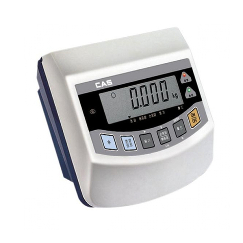
THE FEATURES OF CI-170ASERIES
(1) Features.
■High quality, high accuracy
■Panel-specificindicator (DIN SIZE :96 * 48 mm)
■Appropriate for weight and measurement system
■Easyoperation and various options
■Displayof6 digit(7 segment)
■RFI/EMI screened
■Watchdog circuitry(Systemrestoration).
■Weight back-up(Memorythe weight at sudden power failure)
(2) Main Function
■Store date, time and calculated data at sudden power failure
■Adjustable display rate(Digital filter function)
■Tare weight setting with keys
■Users can set maximum weight which users want to and division at one's disposal
■Self test hardware function
■Independent zero calibration
■Serial printer connection
■External input/output (option)
: 2 external input 4 external output(zero,1 step,2 step, final)
■Print date and timeby inner clock(option)
■Analog out (option)

7
TECHNICAL SPECIFICATION
Analog Part & A/D Conversion
Loadcellexcitation
voltage
DC5 V
Zero adjust range
0.05mV∼5 mV
Input sensitivity
0.2 uV/D (Non-certification)
0.36uV/D(Certification)
Nonlinearity
0.01% F.S.
A/Dinternalresolution
1/1,000,000
A/Dexternalresolution
1/30,000(Max.)
A/Dconversionspeed
320times/sec
Digital Part
Spancalibration
FullDigital Calibration
(Singlepassautomatic span calibration)
Input noise
below ±0.3μVpp
Input impedance
over 10MΩ
Display
7Segment(6 digit)
Maximum capacity
999999
Division
×2, ×5,×10, ×20, ×50
Displaybelowzero
“-“minus signal
Permittedlimit tare
Fullcapacity
Display Part
Description
“STABLE”■LAMP
Weightisstable
“TARE”■LAMP
Tare is used
“NET”■LAMP
ON(NET weight), OFF(GROSS weight)
“HOLD”■LAMP
HoldinWeight
“ZERO”■LAMP
“0”kg
“kg”■LAMP
Use unit kg
“t”■LAMP
Use unit ton

8
General Specification
Power
DC9~24V 1.25A
Size
102.5(W)×100.8(D)×52.5(H)
Temperature
-10℃∼+40℃
Weight
Approx0.4 kg
PowerConsumption
Approx2W
Option Part
Option-1
RS-485(Serial)
Option-2
Inner Clock
Option-3
Analog Out
Option-4
Relay (2 Input, 4Output)

9
MEASURE OF APPEARANCE

10
FRONT PANEL
(1) Display lamp(■)
■ST lamp: turn on when the weight is stable.
■TARE lamp: turn on when tare weight is stored.
■NET lamp: turn on when the current weight is NET weight.
■HOLD lamp: turn on when the weight is held while weighing moving or alive things.
■ZERO lamp: turn on when the current weight is 0 kg.
■KG lamp: turn on when the weight unit is kg.
■TON lamp: turn on when the weight unit is ton.

11
(2) Keyboard
■Used to return thedisplay to the0.
■User set the zero range within 4% or 10% of the maximum capacity(GEN.09).
■Used to enter theTESTmode.
■Used to weigh item by using the container.
■When this key is pressed, the scale stores current weight as the tare weight.
■Ifyou pressTARE key in unload condition, tare setting is released.
■Used to enter theSETmode.
■Use this keyto switch from GROSS to NETweight.
■The annunciators and display will alternate between GROSS and NET as well.
■In case tare weight is REGISTERED, tare plus item's weight is GROSS
weight and onlyitem's weight is NET weight.
■When the lamp turning on, it means NET weight.
■Used to enter the CALmode.
■When you press this key, the current designated printing form is printed.
■Use this key when weighing data is printed.
■Some functions can be defined to the needs.(GEN.20)
■Press andholdSETkey to enterthe menu mode.

12
REAR PANEL
■POWER S/W: POWER ON/OFF
■LOAD CELL : Port for connecting load cell
1 : EX+ 2 : EX- 3 : SIG+ 4 : SIG- 5 : GND
■DC(POWER) : 9~24V1.5A
■SERIAL: RS-232C
■SERIAL: RS-485C (option)
■A-OUT: Analog Out port (V-Out : Voltage, I-Out : Current) (option)
■EXT-IO :External input/output port (option)

13
INSTALLATION & CONNECTION
(1) Load Cell Connection
Pin 1: Excitation voltage+
Pin 2: Excitation voltage-
Pin 3:Sense voltage+
Pin 4:Sense voltage-
Pin 5:Shield
■Connectingmethod
▶Ref. Each L/C
manufacturer's or model's
wire color could be
different. In that case,
please note the following
diagram.
■Manufacturer's wire colors
Connector
Company
Pin 1
(EX+)
Pin 2
(EX-)
Pin 3
(SIG+)
Pin 4
(SIG-)
Pin 5
(GND)
CAS
RED
WHITE
GREEN
BLUE
CASE
KYOWA
RED
BLACK
GREEN
WHITE
CASE
INTERFACE
RED
BLACK
GREEN
WHITE
CASE
P.T
RED
BLACK
GREEN
WHITE
CASE
BLS
GREEN
BLACK
WHITE
RED
YELLOW
SHOWA
RED
BLUE
WHITE
BLACK
CASE
SHINKOH
RED
BLACK
GREEN
WHITE
CASE
TMI
RED
WHITE
GREEN
BLUE
YELLOW
TML
RED
BLACK
WHITE
GREEN
CASE
TFAC
RED
BLUE
WHITE
BLACK
YELLOW
HUNTLEIGH
GREEN
BLACK
RED
WHITE
CASE

14
DISPLAYING METHOD
(1) Number
NUMBER
DISPLAY
NUMBER
DISPLAY
0
5
1
6
2
7
3
8
4
9
(2) Alphabet
Alphabet
DISPLAY
Alphabet
DISPLAY
Alphabet
DISPLAY
Alphabet
DISPLAY
A
H
O
V
B
I
P
W
C
J
Q
X
D
K
R
Y
E
L
S
Z
F
M
T
G
N
U

15
TEST MODE
(1) How to Enter
Turn on the power while pressing the "ZERO" key on the front ofthe indicator.
※When test is done, Press SET key.
(2) Available Keys
Set key: Used for movingto thenext test menu.
Other keys: Used for changing the preset value.
(3) Test Menu(TEST 1 - TEST 8)
TEST1 : Key test
TEST2 : Displaytest
TEST3 : Load cell test and A/D conversion test
TEST4 : Serialinterfacetest
TEST5 : Printertest
TEST6 :A-out test(OPTION)
TEST7 : External input/output test(OPTION)
TEST8 : RTC test(OPTION)
TEST 1
FUNCTION : Keytest
KEY
DISPLAY
DESCRIPTION
SET key : next menu
Other keys: Perform
test
Key number
ex) Incaseof
Zerokey1
Press the key to be test and the No of
key mode should identify with code of
key asthe follows.
If youpress Set key, it willbemoved to
test2.
<Key List>
Keyname
No
ZERO
1
TARE, ◀
2
N/G, ▲
3
PRINT, ▼
4
SET
5

16
TEST 2
FUNCTION : Displaytest
KEY
DISPLAY
DESCRIPTION
SET key : next menu
TEST 2is performed.
If youpress Set key, it willbemoved to
test3
TEST 3
FUNCTION : A/D converter test
KEY
DISPLAY
DESCRIPTION
ZEROkey: Cancel
SET key : next menu
Displaydigitalvalue
of current weight.
ex)
Display digital valueof current weight.
This valuemeans converted digitalvalue
underactualcondition.
If youpress Set key, it will be movedto
test4.
►Note 1. Check whether digital value is changing.
If the digital value is fixed or zero is displayed, please check the connection
ofload cell.
TEST 4
FUNCTION : RS-232, RS-485 test with computer(Serial port)
KEY
DISPLAY
DESCRIPTION
▲Key : Value change
ZEROkey: Cancel
SET key : nextmenu
Waitingfortransmissionand reception
Received: none, Transmitted : 1
►Note 1. Do this test after the connection ofserialport of computer and serial port of
indicator is done.
Note 2. Send no.1 in computer keyboard and check if indicator receives no.1
Sendno.1 in indicator keyboard and check ifcomputer receivesno.1
Note 3. Do this test after baud rateis specified inSETmode (RS-232 : F2-03 and
RS-485 : F2-08).

17
TEST 5
FUNCTION : Printer test(PRINTER)
KEY
DISPLAY
DESCRIPTION
SETkey : next menu
Noerrorinprinter.
Dothistestafter connectionserialprinter.
TEST 6(OPTION)
FUNCTION : A-OUT test
KEY
DISPLAY
DESCRIPTION
▲ Key : Value change
ZEROkey :Cancel
SETkey : next menu
25 P
The output level of Aout is raised by 25%
eachtimethe ▲keyispushed.
TEST 7(OPTION)
FUNCTION : External Input / Output test
KEY
DISPLAY
DESCRIPTION
▲ Key : Value change
ZEROkey :Cancel
SETkey : next menu
I - X O - X
----------
I - 2 O –4
Displayed in the external input section
whenthereis an externalinput.
Push ▲key to execute weighing
external output
input : 2, output : 4
TEST 8 (OPTION)
FUNCTION : RTC test
KEY
DISPLAY
DESCRIPTION
SETkey : next menu
SEC XX
XX : Displaying the progress of seconds
(SEC)

18
CALIBRATION MODE
(1) How to Enter
Turn on the power while pressing “NET/GROSS”keyon the frontoftheindicator.
(2) Calibration Menu(CAL 1 - CAL 9)
CAL1: Maximum capacity set
CAL2: Minimum division set
CAL3: Zero &Span calibration
CAL5: Direct calibration
CAL6: Zero adjustment
CAL7: Factor calibration
CAL8: Gravityadjustment
CAL9: Setting dual range
CAL 1
CAL 1-1
FUNCTION : Set Unit
Set Unit : kg, ton
KEY
DISPLAY
DESCRIPTION
▲, ▼Key:Valuechange
ZEROKey:Cancel
SETKey: Saveand nextmenu
kg
Unit: kg
ton
Unit: ton
CAL 1-2
FUNCTION : Setting Maximum Value
Range of set value : 1 ~ 99,999
KEY
DISPLAY
DESCRIPTION
▲ Key : Value change
◀Key:Digitchange
ZEROKey: Cancel
SETKey: Saveand nextmenu
Max value = 5000 kg
Max value = 20000 kg
►Note 1. Itmeansthe maximumweight valuetobeweighedbythescale.

19
CAL 2
FUNCTION : Minimum division and decimal position setting
Range of set value : 0.001 ~ 50
KEY
DISPLAY
DESCRIPTION
▲, ▼Key:Valuechange
ZEROKey: Cancel
SETKey: Saveand nextmenu
1 kg
0.2 kg
0.05 kg
0.001 kg
►Note 1. To end CAL2, press CANCELkeywhen a decimalpoint is set.
Note2.Settheexternalresolutionwithin1/30,000asthevaluebydividingthemaximum
weightbytheminimumdivision.
Iftheexternalresolutionis1/30,000 or more, Err 21 is shown.
Note3.Thepositionofadecimalpointisdecidedbythepositionofadecimalpointforthe
minimumdivisionsetinCAL2.

20
CAL 3
CAL 3-1
Function: Setting Multi Calibration Step
Range of set value : 1 ~5
KEY
DISPLAY
DESCRIPTION
▲, ▼Key:Valuechange
ZEROKey: Cancel
SETKey: Saveand next
menu
STEP- 1
Settingmulticalibrationforstep1
(CAL3-3andCAL3-4arecarriedoutonce)
STEP- 5
Settingmulticalibrationforstep5
(CAL3-3andCAL3-4arecarriedoutfivetimes.)
►Note 1. A function to use, when the output ofload cell is corrected by setting multiple
points in some sections because the actual curve of load cell is not a straight line.
CAL 3-2
Function: ZeroCalibration
KEY
DISPLAY
DESCRIPTION
ZEROKey: Cancel
SETKey: Saveand next
menu
UnLoAd
Emptytheloadtrayandpressthesetupkey.
1234
Thecurrentweightvalueisdisplayed.
Confirm'Stable'andpressthesetupkey.
---
Zeroinginprogress...
►Note 1. If zeroing finished with no error, it moves to Setting Weight (CAL3-3) although
no key ispressed.

21
CAL 3-3
Function:SettingWeight
Range of set value:1~99,999
KEY
DISPLAY
DESCRIPTION
▲ Key : Value change
◀Key:Digitchange
ZEROKey: Cancel
SETKey: Saveand next
menu
LOAD 1
Itmeanstheweightsettingmode.
(Number=multicalibrationnumber)
W=100.00
100.00(unit:KgorTon)
W= 0.10
0.10(unit:KgorTon)
►Note 1.Settheweightwithinarangeof10%~100%.
CAL 3-4
Function:WeightCalibration
KEY
DISPLAY
DESCRIPTION
ZEROKey: Cancel
SETKey: Saveand next
menu
LoAd
LoadtheweightsetinCAL3-3 andpressthe
setupkey.
12345
Thecurrentweightvalueisdisplayed.
Confirm'Stable'andpressthesetupkey.
---
Spanadjustmentinprogress...
►Note1.CAL3-3andCAL3-4arerepeatedasmanyasSTEPissetinCAL3-1.
Atthistime,theweightvalueshouldbesettoavaluegreaterthanthepreviousone.
Note2.MovetoCAL-3ifthespanadjustmentisoverwithnoerror.
Table of contents
Other CAS Accessories manuals

CAS
CAS CI-600D Series User manual

CAS
CAS CI-502A User manual

CAS
CAS CI-2001A User manual

CAS
CAS CI-2001AS User manual

CAS
CAS CT100 Series User manual

CAS
CAS SW II Series User manual

CAS
CAS CI-6000A Series User manual

CAS
CAS WEIGHING SOLUTION NT-200 Series User manual

CAS
CAS CI-2001A User manual

CAS
CAS DH User manual
Popular Accessories manuals by other brands

KMC Controls
KMC Controls STW-6010 installation guide

Nortek
Nortek M360PIRZ Installation & operation manual

APCO Aviation
APCO Aviation Edge user manual

Allergy Amulet
Allergy Amulet AMULET quick start guide

Siemens
Siemens SIWAREX WL200 Series operating instructions

Festo
Festo SDE1 Series operating instructions