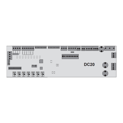
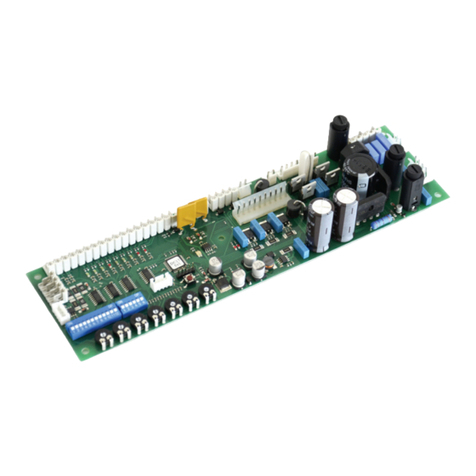
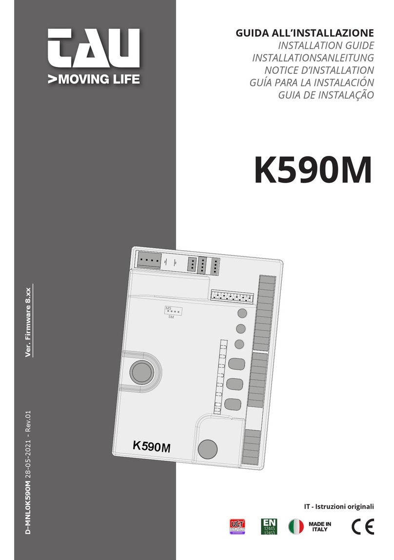
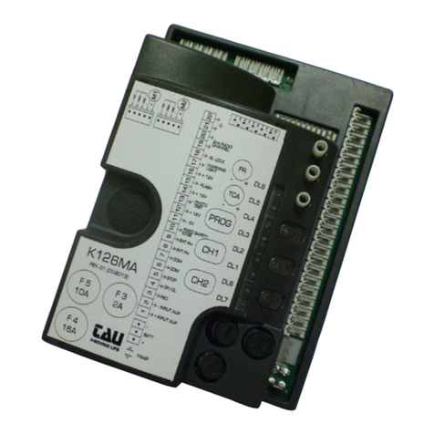
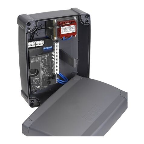
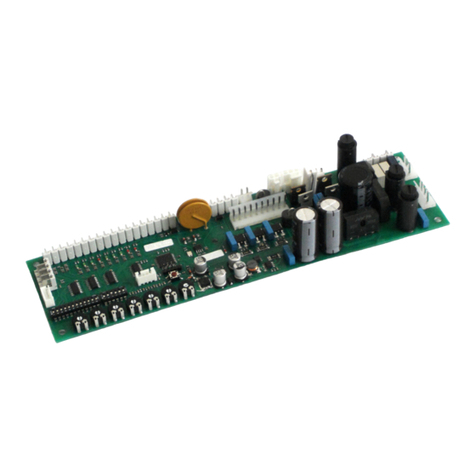
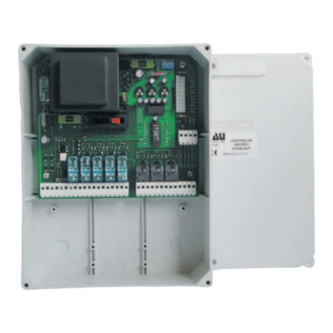
tau K691M User manual

1
GUIDA ALL’INSTALLAZIONE
INSTALLATION GUIDE
INSTALLATIONSANLEITUNG
NOTICE D’INSTALLATION
GUÍA PARA LA INSTALACIÓN
GUIA DE INSTALAÇÃO
IT - Istruzioni originali
K691M
K691M
D-MNL0K691M 29-07-2020 - Rev.18

2
FR
BJ
TCA
+
-
O/C
ENTER
RADIO
F1
10A
F3
2A
F2
10A
Courtesy
light
1 2 3 4 5 6
1 2 3 4 5 6 Antenna
K691M
Dip-switches
M4
ON
GND
+5V
ENC
BATT
OPEN/CLOSE
STOP
PHOTO
ERROR
POWER
TCA
+-
FR
+-
BJ
+-
FS1
TRASF
1
2
3
4
5
6
7
8
9
10
11
18 17
M
+
-
-
+
+
-
DL1
DL2
DL4
DL3
DL5
DL1
DL2
DL4
DL3
DL5
Flashing
light
24 Vdc
max. 15W
+
-
- Photocell TX
+ 24V
Photocells
TX
1 2
Stop
Open/Close
Common
- 0V
Photocell
RX
12345
FS2
SCHEMA
CABLAGGIO
K691M
K691M
WIRING
DIAGRAM
SCHALTPLAN
DER K691M
SCHÉMA
CÂBLAGE
K691M
ESQUEMA DEL
CABLEADO
K691M
ESQUEMA
DE LIGAÇÕES
K691M

3
FR
BJ
TCA
+
-
O/C
ENTER
RADIO
F1
10A
F3
2A
F2
10A
Courtesy
light
1 2 3 4 5 6
1 2 3 4 5 6 Antenna
K691M
Dip-switches
M4
ON
GND
+5V
ENC
BATT
OPEN/CLOSE
STOP
PHOTO
ERROR
POWER
TCA
+-
FR
+-
BJ
+-
FS1
TRASF
1
2
3
4
5
6
7
8
9
10
11
18 17
M
+
-
-
+
+
-
DL1
DL2
DL4
DL3
DL5
DL1
DL2
DL4
DL3
DL5
Flashing
light
24 Vdc
max. 15W
+
-
- Photocell TX
+ 24V
Photocells
TX
1 2
Stop
Open/Close
Common
- 0V
Photocell
RX
12345
FS2
FR
BJ
TCA
O/C
ENTER
RADIO
F1
10A
F3
2A
F2
10A
Courtesy
light
1 2 3 4 5 6
TRASF
1
2
3
4
5
6
7
8
9
DL1
DL2
DL4
DL3
DL5
230 Vac
Power
supply
A

4
AVVERTENZE
Il presente manuale è destinato solamente al personale tecnico qualicato per l’installazione. Nessuna
informazione contenuta nel presente fascicolo può essere considerata d’interesse per l’utilizzatore nale. Questo
manuale è allegato alla centralina K691M; non deve pertanto essere utilizzato per prodotti diversi!
Avvertenze importanti:
Togliere l’alimentazione di rete alla scheda prima di accedervi.
La centralina K691M è destinata al comando di un motoriduttore elettromeccanico in corrente continua per
l’automazione di cancelli, porte e portoni.
Ogni altro uso è improprio e, quindi, vietato dalle normative vigenti.
È nostro dovere ricordare che l’automazione che state per eseguire, è classicata come “costruzione di una
macchina” e quindi ricade nel campo di applicazione della direttiva europea 2006/42/CE (Direttiva Macchine).
Questa, nei punti essenziali, prevede che:
- l’installazione deve essere eseguita solo da personale qualicato ed esperto;
- chi esegue l’installazione dovrà preventivamente eseguire “l’analisi dei rischi” della macchina;
- l’installazione dovrà essere fatta a “regola d’arte”, applicando cioè le norme;
- inne dovrà essere rilasciata al proprietario della macchina la”dichiarazione di conformità”.
Risulta chiaro quindi che l’installazione ed eventuali interventi di manutenzione devono essere eettuati solo da
personale professionalmente qualicato, in conformità a quanto previsto dalle leggi, norme o direttive vigenti.
Nella progettazione delle proprie apparecchiture, TAU rispetta le normative applicabili al prodotto (vedere la
dichiarazione di conformità allegata); è fondamentale che anche l’installatore, nel realizzare gli impianti, prosegua
nel rispetto scrupoloso delle norme.
Personale non qualicato o non a conoscenza delle normative applicabili alla categoria dei “cancelli e porte
automatiche” deve assolutamente astenersi dall’eseguire installazioni ed impianti.
Chi non rispetta le normative è responsabile dei danni che l’impianto potrà causare!
Si consiglia di leggere attentamente tutte le istruzioni prima di procedere con l’installazione.
INSTALLAZIONE
Prima di procedere assicurarsi del buon funzionamento della parte meccanica. Vericare
inoltre che il gruppo motoriduttore sia stato installato correttamente seguendo le relative
istruzioni. Eseguiti questi controlli, assicurarsi che il motoriduttore non abbia un assorbimento
durante il movimento superiore a 3 A (per un corretto funzionamento del quadro di comando).
L’INSTALLAZIONE DELL’APPARECCHIATURA DEVE ESSERE EFFETTUATA “A REGOLA D’ARTE” DA
PERSONALE QUALIFICATO COME DISPOSTO DALLA LEGGE 37/08.
NB: si ricorda l’obbligo di mettere a massa l’impianto nonché di rispettare le normative sulla
sicurezza in vigore in ciascun paese.
LA NON OSSERVANZA DELLE SOPRAELENCATE ISTRUZIONI PUÒ PREGIUDICARE IL BUON
FUNZIONAMENTO DELL’APPARECCHIATURA E CREARE PERICOLO PER LE PERSONE, PERTANTO LA
“CASA COSTRUTTRICE” DECLINA OGNI RESPONSABILITÀ PER EVENTUALI MAL FUNZIONAMENTI E
DANNI DOVUTI ALLA LORO INOSSERVANZA.
1. COLLEGAMENTI ELETTRICI
Tutti i collegamenti elettrici devono essere eseguiti in assenza di tensione all’impianto.
1_ Per aprire il coperchio di protezione ed accedere alla centrale elettronica di controllo di T-SKY
occorre premere sul lato del coperchio e far ruotare lo sportello.
2_ Far passare attraverso i passacavi i cavi di collegamento verso i vari dispositivi, lasciandoli 20÷30cm
più lunghi del necessario. Vedere par. 2.2 per il tipo di cavi e la gura 3 per i collegamenti.
3_ Eseguire i collegamenti dei cavi secondo lo schema di gura 36. Per maggiore comodità, i morsetti
sono estraibili.
ITALIANO

5
1.1 Allacciamento dell’alimentazione
Per l’alimentazione elettrica a T-SKY è suciente collegare la linea 230 Vac al porta fusibile di protezione
del trasformatore.
L’allacciamento dell’alimentazione a T-SKY deve essere eseguito da personale esperto,
qualicato, in possesso dei requisiti richiesti e nel pieno rispetto di leggi, norme e rego-
lamenti.
La linea elettrica di alimentazione deve essere protetta
contro il corto circuito e le dispersioni a terra; deve essere presente un dispositivo che
permetta di staccare l’alimentazione durante l’installazione o la manutenzione di T-SKY.
2. CARATTERISTICHE TECNICHE
Alimentazione scheda 24V AC - 50 Hz
Potenza max. motore c.c. 50 W - 24V DC
Fusibile rapido protezione motore (F1 - 5x20) F 10 A
Fusibile rapido protezione batteria (F2 - 5x20) F 10 A
Fusibile rapido protezione ausiliari 24V DC (F3 - 5x20) T 2A
Tensione circuiti alimentazione motore 24V DC
Tensione alimentazione circuiti dispositivi ausiliari 24V DC
Tensioni alimentazioni circuiti logici 5V DC
Temperatura di funzionamento -20 °C ÷ +55 °C
Grado di protezione del contenitore IP 30
3. LED DI DIAGNOSI
DL1 (OPEN/CLOSE) Led rosso di segnalazione pulsante APRE/CHIUDE
DL2 (STOP) Led verde di segnalazione pulsante STOP
DL4 (PHOTO) Led verde di segnalazione FOTOCELLULA
DL3 (ERR) Led rosso di segnalazione ERRORI
DL5 (POWER) Led verde di segnalazione
PRESENZA RETE (anche tensione batteria)
4. COLLEGAMENTI ALLA MORSETTIERA
FS1 - FS2 Ingresso alimentazione scheda 24 Vac - Alimentato dal trasformatore riposto
nell’apposito vano del motore T-SKY e protetto da fusibile (F 6,3A) sull’alimenta-
zione 230 Vac.
1-4
(Photocell)
Ingresso FOTOCELLULE O DISPOSITIVI DI SICUREZZA attivi in chiusura (contatto
Normalmente Chiuso); il loro intervento, in fase di chiusura provoca l’arresto se-
guito dalla totale riapertura della porta, in fase di apertura provoca la fermata
temporanea dela porta no a rimozione dell’ostacolo rilevato (solo se program-
mato dip switch nr. 3 in ON). Nel caso di più dispositivi di sicurezza, collegare tutti
i contatti NC IN SERIE. 1= FOTOCELLULA.
N.B. Il trasmettittore della fotocellula deve sempre essere alimentato dai morsetti
nr 5 - 6, in quanto su di esso si eettua la verica del sistema di sicurezza (Fototest).
Per eliminare la verica del sistema di sicurezza, o quando non si usano le fotocellule, porre
il dip-switch nr 6 in OFF. Se il fototest non va a buon ne, la centralina non funziona.
ITALIANO

6
2-4 (Stop) Ingresso pulsante STOP (contatto Normalmente Chiuso); Arresta la porta dovun-
que si trovi, inibendo temporaneamente la chiusura automatica, se programma-
ta. Ripartirà di nuovo schiacciando il pulsante APRE/CHIUDEo il radiocomando.
2= STOP, 4= COMUNE.
3-4
(Open/Close) Ingresso pulsante APRE/CHIUDE (contatto Normalmente Aperto); Comanda l’a-
pertura e la chiusura della porta ed è regolato nel funzionamento dai dip-switches
2 e 4. 3= APRE/CHIUDE.
5-6
(Photocell TX) Uscita 24 Vdc, per l’ALIMENTAZIONE DEL TX DELLE FOTOCELLULE (solo quello che
eettua il Fototest) max. nr. 1 trasmettitore fotocellule.
5= NEGATIVO, 6= POSITIVO.
6-7
(Photocell RX) Uscita 24 Vdc, max. 15 W, per l’ALIMENTAZIONE DELLE RX ED EVENTUALI ALTRI
TX DELLE FOTOCELLULE, RICEVITORI ESTERNI, etc; collegare max. n° 3 coppie di
fotocellule. 6= POSiTIVO, 7= NEGATIVO.
8-9
(Flashing light) Uscita LAMPEGGIANTE 24 Vdc, max. 15 W. Il segnale fornito è già opportunamen-
te modulato per l’uso diretto. La frequenza di lampeggio è doppia in fase di chiu-
sura. 8= POSITIVO, 9= NEGATIVO.
10-11 (Antena) Ingresso ANTENNA per RX 433,92 MHz incorporata. 10= MASSA, 11= SEGNALE.
M4 Innesto rapido per connessione ENCODER e MOTORE. Marrone= 5 Vcc (+5V), ver-
de= SEGNALE ENCODER (ENC), Bianco= 0 Vcc (GND), nero= NEGATIVO MOTORE, rosso=
POSITIVO MOTORE.
17 - 18 Ingresso BATTERIE 24V - 1,2Ah.
5. PROCEDURA DI MEMORIZZAZIONE
ATTENZIONE: Dopo aver alimentato il quadro di comando attendere 2 sec. prima di iniziare a
svolgere le manovre di regolazione.
Terminata l’installazione dell’automazione:
Per la programmazione di porte sezionali utilizzare il tasto ENTER.
Per la programmazione di porte basculanti utilizzare il tasto O/C.
1_ premere e mantenere premuto per 3 sec. il tasto ENTER (O/C) sulla scheda no a che l’automazione,
a velocità ridotta, va alla ricerca della battuta di apertura, per poi chiudere completamente. Questo
per acquisire i parametri della corsa (lunghezza, battuta di arresto in chiusura ed in apertura);
Se l’automazione chiude anzichè aprire, fermare la corsa della porta (tramite fotocellule o
premendo il tasto STOP), invertire la polarità del motore e riprendere la procedura dall’i-
nizio.
2_ successivamente, in modo automatico, la porta apre e poi chiude completamente a velocità norma-
le, rallentando in prossimità dei necorsa. Durante queste due fasi, acquisisce punto per punto la
forza necessaria per aprire e chiudere la porta;
3_ la programmazione è terminata con la porta in posizione chiusa. Per iniziare il normale funziona-
mento, è suciente premere il pulsante O/C sulla scheda, oppure il tasto del radiocomando (se
programmato).
ATTENZIONE: se si volesse far eseguire alla centrale una nuova memeorizzazione dei parametri,
è suciente premere e tenere premuto per 3 secondi il tasto ENTER (O/C), la scheda entrerà nuo-
vamente in fase di programmazione ed eettuerà una nuova regolazione che verrà memorizzata
sostituendo la precedente.
N.B.: agendo su qualsiasi regolazione del quadro di comando (trimmer o dip-switches) è necessa-
rio eettuare una manovra completa (apertura e chiusura) dell’automazione per rendere attive
le nuove impostazioni.
In seguito ad un black-out, dopo il ripristino della tensione di rete l’automazione eet-
tuerà, a velocità ridotta, un’apertura ed una chiusura complete per riallinearsi con i pa-
rametri memorizzati.
ITALIANO

7
6. REGOLAZIONI LOGICHE
TRIMMER
T.C.A. Trimmer di regolazione del tempo di chiusura automatica. Da 0 a 120 sec. Ruotando in senso
orario si aumenta il tempo in cui la porta rimane aperta.
FR Trimmer di regolazione della forza durante la fase di apertura e chiusura.
NOTA: ruotando il TRIMMER FR. si può ulteriormente aumentare o diminuire la sensibilità
agli ostacoli. In senso orario aumenta la forza di spinta del motore.
BJ Trimmer di regolazione dell’allentamento (fuoriuscita dal binario) della cinghia/catena al ter-
mine della manovra di chiusura (disponibile dalla versione 5v12).
7. DIP-SWITCH
1on: ad apertura completata, la chiusura della porta è automatica trascorso un tempo impostato sul
trimmer T.C.A.;
o: la chiusura necessita di un comando manuale;
2 on: ad automazione funzionante, una sequenza di comandi di apertura/chiusura induce la porta ad una
APERTURA-CHIUSURA-APERTURA-CHIUSURA, etc. (vedi anche dip switch 4);
o: nelle stesse condizioni, la stessa sequenza di comandi di apertura/chiusura induce la porta ad una
APERTURA-STOP-CHIUSURA-STOP-APERTURA-STOP, etc. (funzione passo-passo);
3on: I rallentamenti sia in apertura che in chiusura sono ridotti del 30% (iniziano dopo rispetto a quelli
standard)
o: I rallentamenti sia in apertura che in chiusura rimangono quelli di fabbrica
Quando si va a modicare la posizione del Dip-switch n°3 si deve eseguire la procedura di
memorizzazione della corsa con il tasto ENTER oppure con il tasto PROG.
4on: funzione NO-REVERSE attiva; la porta ignora i comandi di chiusura durante l’apertura e l’inversio-
ne di marcia avviene solo in fase di chiusura;
o: azionando il pulsante apre-chiude avremo una inversione di marcia anche in fase di apertura;
5 on: la funzione prelampeggio è abilitata;
o: la funzione prelampeggio è disabilitata;
6 on: la funzione “verica delle fotocellule” è inserita;
o: la funzione “verica delle fotocellule” è disinserita. N.B.: da utilizzare quando non si usano le
fotocellule;
8. CARATTERISTICHE DELLA K691M
LED - DL3
Il led, oltre ad indicare la presenza dell’alimentazione, segnala eventuali errori con una serie di lampeggi
predeniti:
• Lampeggio continuo: memorizzazione in corso o setup non terminato;
• sempre acceso: funzionamento regolare;
• 1 lampeggio: tensione della batteria tampone inferiore a 11,3 Vdc;
Controllare l’alimentazione di rete, caricare la batteria, sostituire la batteria;
• 2 lampeggi: errore fototest;
Disabilitare fototest (dip-switch 6 in OFF), vericare funzionamento fotocellule e loro collegamento;
• 3 lampeggi: mancanza tensione di rete;
Controllare interruttore magnetotermico (a monte dell’impianto), controllare fusibili;
• 4 lampeggi: superamento limite max. di corrente;
Picco di eccessivo assorbimento del motoriduttore, controllare l’assenza di ostacoli lungo la corsa della
porta, vericare l’assorbimento di corrente del motore a vuoto e applicato alla porta;
• 5 lampeggi: assenza segnale encoder;
Controllare cablaggio, vericare encoder, vericare che il motore giri liberamente alimentato direttamen-
te dalla batteria, vericare fusibile F1;
• 6 lampeggi: presenza ostacolo;
Controllare l’assenza di ostacoli lungo la corsa della porta e la scorrevolezza della stessa;
ITALIANO

8
• 7 lampeggi: non è stata eseguita alcuna procedura di memorizzazione;
Eseguire procedura di memorizzazione.
• 8 lampeggi: assenza segnale motore;
Controllare cablaggio, vericare che il motore giri liberamente alimentato direttamente dalla batteria,
vericare fusibile F1.
L’indicazione di più errori viene eseguita con una pausa di 2 sec. tra una segnalazione e l’altra. L’indicazione
degli errori persiste no all’esecuzione di una manovra completa (apertura e chiusura) dell’automazione.
In caso di rilevamento di un ostacolo in chiusura, la centrale inverte il movimento ed entra in fase di corsa
rallentata, alla ricerca della battuta di ne corsa in apertura. É necessario che l’automazione completi la ma-
novra di apertura per resettarsi altrimenti, dopo ogni singolo intervento dei dispositivi di sicurezza, ripartirà
la fase di ricerca della battuta di ne corsa in apertura.
Se il rilevamento dell’ostacolo avviene durante un’apertura comandata da orolgio, per riavviare l’automazio-
ne è necessario un comando manuale, tramite radicomando (CH1) o pulsanti, O/C oppure ENTER.
SCHEDA CARICA BATTERIA (INTEGRATA)
Se si collega la batteria, in assenza di rete l’automazione risulta comunque funzionante. Nel caso la
tensione scenda sotto gli 11,3 Vdc, l’automazione cessa di funzionare (il quadro di comando rimane
alimentato); quando, invece, scende sotto i 10,2 Vdc, la scheda sgancia completamente la batteria (il
quadro di comando non è più alimentato).
RILEVAMENTO OSTACOLI
La funzione di rilevamento ostacoli (impostabile tramite trimmer FR) intervenendo in fase di apertura
dell’automazione provoca una richiusura della stessa di 20 cm ca., mentre in fase di chiusura provoca
un’apertura totale.
ATTENZIONE: la logica del quadro di comando può interpretare un attrito meccanico come un
eventuale ostacolo.
N.B.: il pulsante O/C della scheda ha la stessa funzione del tasto APRE/CHIUDE.
9. FUNZIONI AVANZATE
Funzione orologio: è possibile utilizzare un timer (esempio settimanale) collegato all’ingresso del pul-
sante apre-chiude per mantenere aperta la porta in determinate fascie orarie e permetterne poi la
richiusura automatica.
N.B. la porta rimane aperta nchè l’ingresso Ap/Ch rimane impegnato.
Funzione “solo Apre”: ponendo il dip 1 in ON ed il dip 4 in OFF, l’ingresso Ap/Ch funzionerà solo come
comando di apertura, mentre la porta chiuderà esclusivamente una volta trascorso il tempo di chiusura
automatica.
10. RADIO RICEVITORE 433,92 MHZ INTEGRATO
Il radio ricevitore può apprendere no ad un max di 30 codici a rolling code (BUG2R, BUG4R, K-SLIM-RP,
T-4RP) da impostare liberamente.
APPRENDIMENTO RADIOCOMANDI
1_ premere brevemente il tasto RADIO se si desidera associare un radiocomando alla funzione APRE/CHIUDE;
2_ il led DL3 si spegne per indicare la modalità di apprendimento dei codici (se non viene immesso nessun
codice entro 10 secondi, la scheda esce dalla modalità di programmazione);
3_ premere il tasto del radiocomando che si desidera utilizzare;
4_ il led DL3 si riaccende per segnalare l’avvenuta memorizzazione (se ciò non accade, attendere 10
secondi e riprendere dal punto 1);
ITALIANO

9
5_ se si desidera memorizzare altri radiocomandi, ripetere la procedura dal punto 1 no ad un massi-
mo di 30 trasmettitori;
6_ se si desidera uscire dalla modalità di apprendimento senza memorizzare un codice, premere brve-
mente il tasto RADIO.
N.B.: nel caso di raggiungimento del nr massimo di radiocomandi (nr 30), il led DL3 inizierà a
lampeggiare velocemente per circa 3 secondi senza però eseguire la memorizzazione.
PROGRAMMAZIONE REMOTA TRAMITE T-4RP, K-SLIM-RP e BUG-R
È possibile anche eseguire l’apprendimento remoto della nuova versione di radiocomandi T-4RP, K-
SLIM-RP e BUG-R, ossia senza agire direttamente sui tasti di programmazione della ricevente.
Sarà suciente disporre di un radiocomando già programmato nella ricevente per poter aprire la proce-
dura di programmazione remota dei nuovi radiocomandi, programmati tramite TAUPROG.
Attivazione della modalità di autoapprendimento nella centrale e memorizzazione del nuovo
radiocomando.
Questa operazione permette di memorizzare nella centrale il codice del nuovo radiocomando, ma è
necessario possedere un radiocomando “RP” già funzionante. Le successive operazioni si dovranno ese-
guire nelle vicinanze della centrale dell’impianto. Attivazione della modalità di autoapprendimento nella
centrale e memorizzazione del nuovo radiocomando:
1Nel radiocomando già in uso (vecchio) tenendo premuto il tasto del canale 1, premere per 3 volte il
tasto del canale 2.
2 Rilasciare i tasti. Il led del telecomando inizierà a lampeggiare indicando l’abilitazione della modalità
di autoapprendimento.
3Sempre nel radiocomando già in uso (vecchio), premere per almeno 3 secondi, il tasto che attualmen-
te attiva l’automatismo.
4 A questo punto la centrale confermerà il passaggio in modalità di programmazione accendendo il
lampeggiante (salvo per riceventi esterne della serie RXDC).
5 Premere sul nuovo radiocomando il tasto da memorizzare. Se la programmazione è andata a buon
ne il lampeggiante della centrale si spegne.
CANCELLAZIONE RADIOCOMANDI
1_ tenere premuto per 3 secondi ca. il tasto RADIO al ne di cancellare tutti i radiocomandi ad esso associati;
2_ il led DL3 inizia a lampeggiare lentamente per indicare che la modalità di cancellazione è attivata;
3_ rilasciare e premere nuovamente il tasto RADIO per 3 secondi;
4_ il led DL3 si spegne per 3 secondi ca. per poi riaccendersi sso ad indicare l’avvenuta cancellazione;
6_ se si desidera uscire dalla modalità di cancellazione, premere brevemente il tasto RADIO.
ITALIANO

10
DICHIARAZIONE DI INCORPORAZIONE DEL COSTRUTTORE
(ai sensi della Direttiva Europea 2006/42/CE AlI. II.B)
Fabbricante: TAU S.r.l.
Indirizzo: Via E. Fermi, 43 - 36066 Sandrigo (Vi) ITALIA
Dichiara sotto la propria responsabilità che il prodotto: Centrale di comando
realizzato per il movimento automatico di: Porte Garage
per uso in ambiente: Residenziale / Condominiale completo di: Radioricevente e scheda carica batteria
Modello: K691M Tipo:K691M
Numero di serie: vedi etichetta argentata
Denominazione commerciale: Quadro di comando per uno motore 24V con encoder
È realizzato per essere incorporato su una chiusura (cancello a battente) o per essere assemblato con altri dispositivi
al fine di movimentare una tale chiusura per costituire una macchine ai sensi della Direttiva Macchine 2006/42/CE.
Dichiara inoltre che questo prodotto è conforme ai requisiti essenziali di sicurezza delle seguenti ulteriori direttive CEE:
- 2006/95/CE Direttiva Bassa Tensione - 2004/108/CE Direttiva Compatibilità Elettromagnetica
ed, ove richiesto, alla Direttiva: -1999/5/CE Apparecchiature Radio e apparecchiature terminali di telecomunicazione
Dichiara inoltre che non è consentito mettere in servizio il macchinario fino a che la macchina in cui sarà incor-
porato o di cui diverrà componente sia stata identificata e ne sia stata dichiarata la conformità alle condizioni della
Direttiva 2006/42/CE.
Si impegna a trasmettere, su richiesta adeguatamente motivata delle autorità nazionali, informazioni pertinenti sulle
quasi-macchine.
Sandrigo, 26/11/2014 Il Rappresentante Legale
_________________________________________
Loris Virgilio Danieli
Nome e indirizzo della persona autorizzata a costituire la documentazione tecnica pertinente:
Loris Virgilio Danieli - via E. Fermi, 43 - 36066 Sandrigo (Vi) Italia
ITALIANO

11
WARNINGS
This manual is designed to assist qualied installation personnel only. It contains no information that may be
of interest to nal users. This manual is attached to the K691M control unit, therefore it may not be used for
dierent products!
Important warnings:
Disconnect the mains power supply to the board before accessing it.
The K691M control unit is suitable for the control of a direct-current electromechanical gearmotor for automat-
ing gates and doors of all kinds.
Any other use is considered improper and is consequently forbidden by current laws.
Please note that the automation system you are going to install is classi ed as “machine construction” and
therefore is included in the application of European directive 2006/42/EC (Machinery Directive).
This directive includes the following prescriptions:
- Only trained and qualied personnel should install the equipment;
- the installer must rst make a “risk analysis” of the machine;
- the equipment must be installed in a correct and workmanlike manner in compliance with all the stand-
ards concerned;
- after installation, the machine owner must be given the “declaration of conformity”.
This product may only be installed and serviced by qualied personnel in compliance with current, laws,
regulations and directives.
When designing its products, TAU observes all applicable standards (please see the attached declaration
of conformity) but it is of paramount importance that installers strictly observe the same standards when
installing the system.
Unqualied personnel or those who are unaware of the standards applicable to the “automatic gates and
doors” category may not install systems under any circumstances.
Whoever ignores such standards shall be held responsible for any damage caused by the system!
Do not install the unit before you have read all the instructions.
INSTALLATION
Before proceeding, make sure the mechanical components work correctly. Also check that the
gear motor assembly has been installed according to the instructions. Then make sure that the
power consumption of the gear motor is not greater than 3A (otherwise the control panel may
not work properly).
THE EQUIPMENT MUST BE INSTALLED “EXPERTLY” BY QUALIFIED PERSONNEL AS REQUIRED BY LAW.
Note: it is compulsory to earth the system and to observe the safety regulations that are in force
in each country.
IF THESE ABOVE INSTRUCTIONS ARE NOT FOLLOWED IT COULD PREJUDICE THE PROPER WORKING OR-
DER OF THE EQUIPMENT AND CREATE HAZARDOUS SITUATIONS FOR PEOPLE. FOR THIS REASON THE
“MANUFACTURER” DECLINES ALL RESPONSIBILITY FOR ANY MALFUNCTIONING AND DAMAGES THUS
RESULTING.
1. ELECTRICAL CONNECTIONS
All electrical connections must be made withthe system disconnected from the power
supply.
1_ To open the protection cover and access the electronic control unit of T-SKY, press on the side of
the cover and turn the panel door.
2_ Route the connection cables to the various devices through the cable clamps, leaving a length
20÷30cm more than necessary. See para. 2.2 for the type of cables and gure 3 for connections.
3_ Make the connections as shown in the diagram in gure 36. Terminals are removable to facilitate
connections.
1.1 Connecting to the power supply
For electric power supply of T-SKY simply connect the 230 Vac line to the transformer safety fuse holder .
ENGLISH

12
T-SKY must be connected to the power mains by skilled and qualied personnel, in possession
of all requirements for full compliance with all legal provisions, standards and regulations.
The electric power line must be protectedagainst short circuits and dispersion to earth; a
device must be tted to enable shuto of the power supply during installation or main-
tenance of T-SKY.
2. TECHNICAL SPECIFICATIONS
Board power supply 24V AC - 50 Hz
Max. DC motor power 50 W - 24V DC
Quick-acting motor protection fuse (F1 - 5x20) F 10 A
Quick-acting battery protection fuse (F2 - 5x20) F 10 A
Quick-acting 24 Vdc auxiliary circuit protection fuse (F3 - 5x20) T 2A
Motor power circuit supply voltage 24V DC
Auxiliary device circuit power supply voltage 24V DC
Logic circuit power supply voltage 5V DC
Operating temperature -20 °C ÷ +55 °C
Housing protection rating IP 30
3. DIAGNOSTICS LEDS
DL1 (OPEN/CLOSE) red led indicating use of OPEN/CLOSE button
DL2 (STOP) green led indicating use of STOP button
DL4 (PHOTO) green led indicating PHOTOCELL
DL3 (ERR) red led indicating ERRORS
DL5 (POWER) green led indicating POWER ON (also when battery powered)
4. TERMINAL BOARD CONNECTIONS
FS1 - FS2 24 Vac board power supply input – Powered by transformer in relative compart-
ment of T-SKY motor and protected by fuse (F 6,3A) on the 230 Vac power line.
1-4 (Photocell) PHOTOCELL OR SAFETY DEVICE input active on closure (Normally Closed con-
tact); when activated, during the closing phase, generates a door stop com-
mand followed by complete door re-opening; in the opening phase generates
a temporary stop command until the detected obstacle is removed (only if dip
switch nr. 3 is set to ON). In the case of multiple safety devices, connect all NC
contacts IN SERIES. 1= PHOTOCELL
N.B. The photocell transmitter must always be powered by terminals 5 and 6, as the safety
system check is performed on the latter (Fototest).
To disable the safety system test function, or when using the photocells, set dipswitch 6 to
OFF. If the fototest function fails, there is a control unit fault.
2-4 (Stop) STOP button input (Normally Closed contact); stops the door at any point of
travel, temporarily inhibiting automatic closure, if programmed. It resumes
operation when the OPEN/CLOSE button is pressed or radio control is used.
2= STOP, 4= COMMON
3-4 (Open/Close) OPEN/CLOSE button input (Normally Open contact); activates door opening and
closing and is controlled by operation of dipswitches 2 and 4. 3= OPEN/CLOSE
ENGLISH

13
5-6 (Photocell TX) 24 Vdc output, for PHOTOCELL TX POWER SUPPLY (only those that perform
the Fototest function) max. nr. 1 photocell transmitter.
5= NEGATIVE, 6= POSITIVE
6-7 (Photocell RX) 24 Vdc output, max. 15 W, for POWER SUPPLY OF RX AND POSSIBLE OTHER TX
ELEMENTS OF PHOTOCELLS, EXTERNAL RECEIVERS etc; connect max. 3 pairs
of photocells. 6= POSITIVE, 7= NEGATIVE.
8-9 (Flashing light) 24 Vdc FLASHING LIGHT output (max. 15 W). The signal supplied is already
specially modulated for direct use. The ashing frequency doubles during the
closing phase. 8= POSITIVE, 9= NEGATIVE.
10-11 (Antenna) AERIAL input for built-in RX 433,92 MHz. 10= EARTH, 11= SIGNAL.
M4 quick connector for ENCODER and MOTOR connection. Brown = 5 Vdc (+5V),
green = ENCODER SIGNAL (ENC), White = 0 Vdc (GND), black = MOTOR NEGATIVE,
red = MOTOR POSITIVE.
17 - 18 24V – 1.2Ah BATTERY input.
5. Memorisation procedure
IMPORTANT: After powering up the control panel, wait for 2 seconds before starting the adjust-
ment procedures.
Once you have nished installing the automation system:
To program section doors use the ENTER button. To program up-and-over doors use the
O/C button.
1_ hold the ENTER (O/C) key on the board down for 3 sec. until the automation system will seek the
opened position stop at reduced speed and will then closes fully. This serves to allow the system to
acquire the travel parameters (length, closed and open position stops);
If the automation closes instead of opening, stop the run of the door (by cutting the
photocells or closing the STOP contact), invert the polarity of the motor and restart the
procedure from the beginning.
2_ the door then opens automatically and closes again fully at normal speed, slowing as it approaches
the travel limit stops/limit switches. During these two stages, the system acquires, point by point,
the force required to open and close the door;
3_ programming ends with the door in the closed position. To start regular operation, simply press the
O/C button on the board, or the key on the remote control (if programmed).
NOTE: if you want the control unit to perform a new parameter storing procedure, simply hold
down the ENTER (O/C) key for 3 seconds; the board will enter programming mode again and will
run a new adjustment cycle, which will be stored in the memory, replacing the previous one.
Note: by means of any adjustment device on the control panel (trimmers or dipswitches) per-
form a complete manoeuvre (opening and closing) of the automation to apply the new settings.
After a power outage, the opener will perform a full cycle (opening + closing) at a slow
speed to reset the ope-rating parameters to the values originally saved.
6. LOGIC SETTINGS
TRIMMER
T.C.A. Automatic closing time setting trimmer. From 0 to 120 sec.
Turn clockwise to increase the length of time the door stays open.
FR Trimmer for adjustment of force during the opening phase.
NOTE: you can turn the FR TRIMMER to further increase or decrease obstacle sensitivity.
ENGLISH

14
Turning clockwise increases the motor’s operating force.
BJ Trimmer that regulates the loosening of the belt/chain from the track at the end of the clo-
sing operation (available from version 5v12)
7. DIP-SWITCHES
1 on: at the end of opening, the door closes automatically after a time interval set on the trimmer
A.C.T.;
o: closure requires a manual command;
2 on: with the automation running, a sequence of open/close commands activates a door sequence
OPEN-CLOSE-OPEN-CLOSE, etc. (see also dip switch 4);
o: in the same conditions, a sequence of open/close commands activates a door sequence OPEN-
STOP-CLOSE-STOP-OPEN-STOP, etc. (step-step function);
3on: slowdowns both during opening and closing operations are reduced by 30% (they start after the
factory settings’ ones)
o: factory settings’ slowdowns both during opening and closing operations
When changing the position of Dip-switch n°3, you must carry out the stroke setup
procedure through ENTER of PROG buttons.
4 on: NO-REVERSE function active; the door ignores the closing commands during opening and inverts
the direction of door travel only in the closing phase;
o: on activation of the open-close button, the direction of travel is inverted also in the opening phase;
5 on: the pre-ashing function is enabled;
o: the pre-ashing function is disabled;
6 on: the “photocell check” function is enabled;
o: the “photocell check” function is disabled. N.B. to be used when photocells are not used;
8. FEATURES OF K691M
LED - DL3
As well as indicating the presence of power, this led indicates any errors by means of a set series of
ashing signals:
• Continuous ashing: storage in progress or setup not completed;
• always lit: normal operation;
• 1 ash: backup battery voltage less than 11.3 Vdc;
Check the mains voltage, charge the battery, replace the battery;
• 2 ashes: fototest error;
Disable fototest (dipswitch 6 set to OFF), check photocell operation and relative connection;
• 3 ashes: mains power failure;
check thermal magnetic cut-out (upline of system), check fuses;
• 4 ashes: max. current limit exceeded;
Peak of excessive motor absorption, ensure absence of obstacles along door travel, check motor absorp-
tion under no load and applied on the door;
• 5 ashes: no encoder signal;
check wiring, check encoder, check that the motor rotates freely when powered directly by battery, check
fuse F1;
• 6 ashes: presence of obstacle;
Ensure absence of obstacles along door travel and smooth movement of the door;
• 7 ashes: no memorisation procedure performed;
Perform memorisation procedure.
• 8 ashes: no motor signal;
check wiring, check that the motor rotates freely when powered directly by battery, check fuse F1;
ENGLISH

15
Multiple error signals are indicated with a pause of 2 seconds between one signal and the next. The er-
ror signals persist until a complete automation manoeuvre is performed (opening and closing).
If an obstacle is detected while closing, the control unit reverses the movement and switches to slow
mode as it searches for the closing travel limit. To reset the automation must complete the opening
cycle, if not, every time the safety device is activated the automation will search for the travel limit.
If the obstacle is detected during a timed opening, a manual command via remote control (CH1) or but-
tons, O/C or ENTER is required to restart the automation.
BATTERY CHARGE CARD (BUILT-IN)
If the battery is connected, the automation will be operative also in the event of a power failure. If volt-
age falls below 11.3 Vdc, the automation stops operating (the control panel remains powered); if it falls
below 10.2 Vdc, the card disconnects the battery completely (the control panel is no longer powered).
OBSTACLE DETECTION
The obstacle detection function (settable via the trimmer FR), if activated during the opening phase, re-
closes the door by approx. 20 cm, and during closing activates a complete opening cycle.
IMPORTANT: the control panel logic may interpret mechanical friction as an obstacle.
N.B. the O/C button on the card has the same function as the OPEN/CLOSE key.
9. ADVANCED FUNCTIONS
Clock function: a timer may be used (e.g. weekly), connected to the input of the open-close button, to keep
the door open in set time intervals, to then enable automatic re-closure.
N.B. the door remains open while the Op/Cl input is engaged.
Open only” function: by setting dipswitch 1 to ON and dipswitch 4 to OFF, the Op/Cl input will only operate
as an opening command, while the door will close exclusively after the set interval for automatic closure.
10. BUILT-IN 433.92 MHZ RADIO RECEIVER
The radio receiver can learn up to max. 30 codes in rolling codes (BUG2R, BUG4R, K-SLIM-RP, T-4RP) set
as required.
RADIO CONTROL LEARNING
1_ briey press the key RADIO to associate a radio control with the function OPEN/CLOSE;
2_ led DL3 turns o to indicate code learning mode (if no code is entered within 10 seconds, the card
exits programming mode);
3_ press the key of the radio control to be used;
4_ led DL3 turns on again to conrm memorisation (if this does not occur, wait 10 seconds and repeat
the steps from point 1);
5_ to memorise other radio controls, repeat the procedure from point 1, for up to a maximum of 30
transmitters.
6_ to exit learning mode without memorising a code, briey press the key RADIO.
N.B.: if the maximum number of radio controls is reached (30), led DL3 ashes quickly for ap-
prox. 3 seconds, without performing memorisation.
REMOTE PROGRAMMING VIA T-4RP, K-SLIM-RP and BUG-R
It is also possible to learn the new versions of the radio controls T-4RP, K-SLIM-RP and BUG-R remotely,
i.e. without acting directly on the receiver programming keys.
A radio control previously programmed on the receiver is all that is needed to open the remote pro-
gramming procedure for new radio controls, programmed via TAUPROG.
Activation of self-learning mode of the control unit and memorisation of the new radio control.
This operation enables memorisation of the new radio control code on the control unit, but an operational
“RP” radio control must already be available. The subsequent operations must be performed in the vicinity
ENGLISH

16
of the system control unit. Activation of self-learning mode on the control unit and memorisation of the new
radio control:
1On the operative (old) radio control, press and hold the key for channel 1, and press the channel 2
key three times.
2Release the keys. The radio control led starts ashing to indicate that the self-learning mode is enabled.
3Still on the operative (old) radio control, press the key currently used to activate the automation for
at least 3 seconds.
4At this point the control unit conrms changeover to programming mode by activating the ashing
light (except for external receivers in the RXDC series).
5 Press the radio control key to be memorised again. If programming is successful, the control unit
ashing light turns o.
DELETING RADIO CONTROLS
1_ press and hold the RADIO key for approx. 3 seconds to delete all associated radio controls;
2_ led DL3 starts ashing slowly to indicate that deletion mode is enabled;
3_ release the RADIO key and press again for 3 seconds;
4_ led DL3 turns o for approx. 3 seconds, and then remains lit to conrm deletion;
5_ to exit deletion mode, briey press the RADIO key.
MANUFACTURER’S DECLARATION OF INCORPORATION
(in accordance with European Directive 2006/42/EC App. II.B)
Manufacturer: TAU S.r.l.
Address: Via E. Fermi, 43 - 36066 Sandrigo (Vi) ITALY
Declares under its sole responsibility, that the product: Electronic control unit
designed for automatic movement of: Garage door
for use in a: Residential / Communities complete with: Radioreceiver and battery charger board
Model: K691M Type:K691M
Serial number: see silver label Commercial name: Control panel for one 24V motors with encoder
Has been produced for incorporation on an access point (swing gate) of for assembly with other devices used to
move such an access point, to constitute a machine in accordance with the Machinery Directive 2006/42/CE.
Also declares that this product complies with the essential safety requirements of the following CEE directives:
- 2006/95/CE Low Voltage Directive - 2004/108/CE Electromagnetic Compatibility Directive
and, where required, with the Directive:- 1999/5/CE Radio equipment and telecommunications terminal equipment
Also declares that it is not permitted to start up the machine until the machine in which it is incorporated or of
which it will be a component has been identied with the relative declaration of conformity with the provisions of
Directive 2006/42/CE.
The manufacturer undertakes to provide, on sufciently motivated request by national authorities, all information
pertinent to the quasi-machinery.
Sandrigo, 26/11/2014 Legal Representative
_________________________________________
Loris Virgilio Danieli
Name and address of person authorised to draw up all pertinent technical documentation:
Loris Virgilio Danieli - via E. Fermi, 43 - 36066 Sandrigo (Vi) Italy
ENGLISH

17
HINWEISE
Das vorliegende Handbuch ist nur für technisches, zur Installation qualiziertes Personal bestimmt.
Die im vorliegenden Heft enthaltenen Informationen sind für den Endbenutzer nicht interessant. Diese
Anleitung liegt der Steuerung K691M bei und darf daher nicht für andere Produkte verwendet werden!
Wichtige Hinweise:
Vor Eingrien an der Steuerkarte die Netzstromversorgung abtrennen.
Die Steuerung K691M dient zum Steuern eines elektromechanischen Gleichstromgetriebemotors für
die Automatisierung von Türen und Toren.
Jeder andere Einsatz ist unsachgemäß und daher laut gültiger Vorschriften verboten.
Unsere Picht ist, Sie daran zu erinnern, dass die Automatisierung, die Sie ausführen werden, als „Ma-
schinenkonstruktion“ klassiert ist und daher zum Anwendungsbereich der Europäischen Richtlinie
2006/42/CE (Maschinenrichtlinie) gehört.
Nach den wichtigsten Punkten dieser Vorschrift:
- darf die Installation ausschließlich von erfahrenem Fachpersonal ausgeführt werden;
- muss jener, der die Installation ausführt, vorher eine „Risikoanalyse“ der Maschine machen;
- muss die Installation “fachgerecht” bzw. unter Anwendung der Vorschriften ausgeführt sein;
- muss dem Besitzer der Maschine die „Konformitätserklärung” ausgehändigt werden.
Es ist daher oensichtlich, dass Installation und eventuelle Wartungseingrie nur von beruich quali-
ziertem Personal in Übereinstimmung mit den Verordnungen der gültigen Gesetze, Normen und Vor-
schriften ausgeführt werden dürfen.
Bei der Planung ihrer Apparaturen hält sich TAU an die für das Produkt anwendbaren Vorschriften
(siehe anliegende Konformitätserklärung); von grundlegender Wichtigkeit ist, dass sich auch der Instal-
lateur bei der Durchführung der Anlage genauestens an die Vorschriften hält.
Personal, das nicht qualiziert ist oder die Vorschriften nicht kennt, die für die Kategorie “automatische
Türen und Tore” anwendbar sind, darf Installationen und Anlagen keinesfalls ausführen.
Wer sich nicht an die Vorschriften hält, haftet für die Schäden, die von der Anlage verursacht
werden können.
Vor der Installation bitte alle Anweisungen genau lesen.
INSTALLATION
Bevor man weitermacht, den korrekten Betrieb des mechanischen Teils überprüfen und konrollieren,
ob der Getriebemotor richtig nach den jeweiligen Anweisungen installiert ist. Nachdem diese Kontrol-
len ausgefürt sind, muss sichergestellt werden, dass der Getriebemotor nicht mehr als 3A Stromaufnah-
me hat (für den korrekten Betrieb der Steuertafel).
DAS GERÄT MUSS GEMÄß GESETZ FACHGERECHT VON QUALIFIZIERTEM PERSONAL INSTALLIERT WERDEN.
Anmerkung: Bitte beachten Sie, dass die Erdung der Anlage und die Einhaltung der in jedem Land gülti-
gen Sicherheitsvorschriften Picht ist.
DAS NICHTEINHALTEN DER OBEN ANGEFÜHRTEN ANLEITUNGEN KANN DEN EINWANDFREIEN BETRIEB DES
GERÄTS BEEINTRÄCHTIGEN UND GEFAHREN FÜR PERSONEN HERVORRUFEN. DER HERSTELLER HAFTET DAHER
NICHT FÜR BETRIEBSSTÖRUNGEN UND SCHÄDEN, DIE AUF DAS NICHTEINHALTEN DER ANLEITUNGEN ZU-
RÜCKZUFÜHREN SIND.
1. ELEKTRISCHE ANSCHLÜSSE
Alle Stromanschlüsse müssen ohne Anlagenspannung ausgeführt werden.
1_ Um den Schutzdeckel zu önen und an die elektronische Steuerung von T-SKY zu gelangen, muss
auf die Seite des Deckels gedrückt und die Klappe wie in Abb. 35 gezeigt gedreht werden .
2_ Die Anschlusskabel durch den Kabelkanal an die verschiedenen Vorrichtungen ziehen und sie 20-
30 cm länger als notwendig belassen. Siehe Abschn. 2.2 für den Kabeltyp und die Abbildung 3 für
die Anschlüsse.
DEUTSCH

18
3_ Den Anschluss der Kabel nach dem Schema. Um die Anschlüsse zu erleichtern, sind die Klemmen
abziehbar.
1.1. Anschluss der Speisung
Für die Stromspeisung von T-SKY ist es ausreichend, die 230Vac-Leitung an den Sicherungsträger des
Trafos zu schließen.
Der Anschluss der Speisung von T-SKY muss von erfahrenem Fachpersonal mit den erfor-
derlichen Kenntnissen und unter voller Einhaltung von Gesetzen, Vorschriften und Ver-
ordnungen ausgeführt werden.
Die Stromspeisungsleitung muss gegen Kurzschluss und Erdfehler geschützt werden; es
muss eine Vorrichtung vorliegen, die die Speisung während der Installation oder Wartung
des T-SKY unterbricht.
2. TECHNISCHE MERKMALE
Kartenspeisung 24V AC - 50 Hz
Höchstleistung Motor Gleichstrom 50 W - 24V DC
Motorenschutzsicherung (F1 – 5x20) F 10 A
Batterieschutzsicherung (F2 – 5x20) F 10 A
Schutzsicherung Nebenkreise (24 V dc (F3 – 5x20) T 2A
Spannung Motorenspeisungskreise 24V DC
Spannung Speisung Kreise zusätzliche Vorrichtungen 24V DC
Spannungen Speisungen logische Kreise 5V DC
Betriebstemperatur -20 °C ÷ +55 °C
Schutzgrad des Behälters IP 30
3. DIAGNOSE-LEDS
DL1 (OPEN/CLOSE) Rote Melde-Led Druckknopf ÖFFNEN/SCHLIESSEN
DL2 (STOP) Gründe Anzeige-Led Druckknopf STOPP
DL4 (PHOTO) Grüne Anzeige-Led - PHOTOZELLE
DL3 (ERR) Rote Anzeige-Led FEHLER
DL5 (POWER) Grüne Anzeige-Led NETZSPANNUNG (auch Batteriespannung)
4. ANSCHLÜSSE AN DAS KLEMMENBRETT
FS1 - FS2 Eingang Speisung Karte 24 Vac – Speisung durch Trafo im hierfür vorgesehenen Raum
des Antriebs T-SKY, durch eine Sicherung (F 6,3A) an der 230 Vac-Speisung geschützt.
1-4
(Photocell)
Eingang PHOTOZELLEN ODER SICHERHEITSVORRICHTUNGEN beim Schließen aktiv
(Normalerweise Geschlossener Kontakt); ihr Eingri während der Schließung ruft den
Stopp und eine ganze Önung des Tors hervor; in der Önungsphase wird der vor-
übergehende Stillstand des Tors bis zur Entfernung des erfassten Hindernisses her-
vorgerufen (nur wenn der Dip Switch Nr. 3 auf ON gestellt ist). Im Falle mehrerer
Sicherheitsvorrichtungen, müssen alle NC-Kontakte SERIENGESCHALTET werden. 1 -
PHOTOZELLE.
DEUTSCHDEUTSCH

19
HINWEIS: Der Sender der Photozelle muss immer durch die Klemmen 5-6 gespeist wer-
den, da durch ihn die Prüfung des Sicherheitssystems ausgeführt wird (Fototest).
Zur Beseitigung der Prüfung des Sicherheitssystems, oder wenn die Photozellen nicht verwen-
det werden, wird der Dip-Switch Nr. 6 auf OFF gestellt. Wenn der Phototest negativ erfolgt,
funktioniert die Steuerung nicht.
2-4 (Stop) Eingang Druckknopf STOPP (Normalerweise geschlossener Kontakt); stoppt das Tor
in jeder Position und untersagt gleichzeitig das automatische Schließen, wenn dies
programmiert ist. Es bewegt weiter, wenn der Druckknopf ÖFFNEN/SCHLIESSEN über
die Fernsteuerung gedrückt wird. 2= STOPP, 4= GEMEINSAM.
3-4
(Open/Close)
Eingang Druckknopf ÖFFNEN/SCHLIESSEN (Kontakt normalerweise geönet); steuert
die Önung und Schließung des Tor und wird im Betrieb durch die Dip-Switches 2 und
4 geregelt. 3= ÖFFNEN/SCHLIESSEN.
5-6 (Photocell
TX)
Ausgang 24 Vac W für die SPEISUNG des TX DER PHOTOZELLEN (nur der, der den Pho-
totest ausführt) max. 1 Photozellensender.
5= NEGATIV, 6= POSITIV.
6-7 (Photocell
RX)
Ausgang max. 24 Vdc 15 W zur SPEISUNG DER RX UND EVENTUELLER ANDERER TX DER
PHOTOZELLEN, EXTERNE EMPFÄNGER usw.; max. 3 Photozellenpaare anschließen. 6=
POSITIV, 7= NEGATIV.
8-9 (Flashing
light)
Ausgang BLINKLEUCHTE max. 24 Vac. 15 W. Das gegebene Signal wurde schon für die
direkte Anwendung moduliert. Die Blinkhäugkeit ist in der Schließphase doppelt. 8=
POSITIV, 9= NEGATIV.
10-11
(Antenna)
Eingang ANTENNE für integrierten RX 433,92 MHz. 10= ERDE, 11= SIGNAL.
M4 Schnellkupplung für Anschluss ENCODER und MOTOR. Braun= 5 Vcc (+5V), grün= EN-
CODER-SIGNAL (ENC), Weiß= 0 Vcc (GND), schwarz= NEGATIV MOTOR, rot= POSITIV MOTOR.
17 - 18 Eingang BATTERIEN 24V - 1,2Ah.
5. SPEICHERVERFAHREN
ACHTUNG: Nachdem die Steuertafel gespeist wurde, 2 Sek. Warten, bevor die Einstellbewegun-
gen begonnen und ausgeführt werden.
Nach Abschluss der Installation der Automatisierung:
Verwenden Sie für die Programmierung der Sektionaltore die Taste ENTER.
Verwenden Sie für die Programmierung der Schwenktore die Taste O/C.
1_ Die Taste ENTER (O/C) auf der Karte drücken und für drei Sekunden gedrückt halten bis die Auto-
matisierung sucht den Anschlag Önung mit reduzierter Geschwindigkeit und schließt sich dann
vollständig. Dies dient zur Erfassung der Parameter des Hubs (Länge, Anschlag bei Schließung und
bei Önung);
Halten Sie die Bewegung des Tors an (mit den Fotozellen oder durch Schließung des Kon-
takts STOP), vertauschen Sie die Polarität der Motor und das Verfahren vom Beginn wieder-
holen, wenn sich das Tor schließt, statt sich zu önen.
2_ Anschließend önet sich die Tür automatisch, schließt dann mit normaler Geschwindigkeit un ver-
langsamt in der Nähe der Endschalter. Während dieser beiden Phasen erfasst sie Punkt für Punkt
die kraft, die für das Önen und Schließen der Tür erforderlich ist;
3_ Die Programmierung ist abgeschlossen, wenn sich die Tür in der geschlossenen Position bendet.
Zum Starten des normalen Betriebs ist es ausreichend, die Taste O/C auf der Karte oder die Taste
der Fernsteuerung (falls programmiert) zu drücken.
ACHTUNG: Wenn das Steuergerät eine neue Abspeicherung der Parameter vornehmen soll, ist es
ausreichend, die Taste ENTER (O/C) zu drücken und drei Sekunden gedrückt zu halten; die Karte
DEUTSCHDEUTSCH

20
wechselt erneut zur Phase Programmierung und nimmt eine neue Einstellung vor, die abgespei-
chert wird und die vorausgehende ersetzt.
HINWEIS: Durch Einwirkung auf eine beliebige Einstellung der Schalttafel (Trimmer oder Dip-Swit-
ches) muss eine vollständige Bewegung der Automatisierung ausgeführt werden (Önung und
Schließung), um die neuen Einstellungen zu aktivieren.
Nach einem Stromausfall wird das Tor langsam geönet und dann geschlossen: so blei-
ben die eingelernten Kraftwerte gespeichert.
6. LOGISCHE EINSTELLUNGEN
TRIMMER
T.C.A. Einstelltrimmer der automatischen Schließzeit. 0 bis 120 Sek.
Durch Drehen in Uhrzeigersinn wird die Zeit angehoben, für die die Tür oen bleibt.
FR Regeltrimmer der Kraftausübung während der Önungsphase.
ANMERKUNG: Durch Drehen von TRIMMER FR. Kann die Hindernisempndlichkeit weiter an-
gehoben oder gesenkt werden. In Uhrzeigersinn nimmt die Schubkraft des Mo-
tors zu.
BJ Trimmer zum Einstellen des Durchhangs (Austritt aus der Spur) des Riemens / der Kette am
Ende des Schließmanövers (verfügbar ab Version 5v12).
7. DIP-SWITCH
1 on: Nach abgeschlossener Önung erfolgt die Schließung des Tors nach der Zeitspanne automa-
tisch, die im Trimmer T.C.A. eingestellt ist;
o: Die Schließung benötigt eine manuelle Steuerung;
2 on: Bei funktionierender Automatisierung führt eine Önungs-/Schließfolge zu einer ÖFFNUNG-
SCHLIESSUNG-ÖFFNUNG-SCHLIESSUNG usw. des Tors. (siehe auch Dip-Switch 4);
o: Unter denselben Bedingungen führt dieselbe Önungs-/Schließfolge zu einer ÖFFNUNG-STOPP-
SCHLIESSUNG-STOPP-ÖFFNUNG-STOPP usw. (Schrittbetrieb);
3on: Die Verlangsamung sowohl beim Önen als auch beim Schließen wird um 30% reduziert (es
beginnt später als die Standardläufe)
o: Die Verlangsamungen beim Önen und Schließen bleiben die werkseitigen eingestellten.
Wenn Sie die Position des Dip-Schalters Nr. 3 ändern, müssen Sie die Speicherung des
Fahrt mit der ENTER-Taste oder mit der PROG-Taste durchführen.
4 on: Funktion NO-REVERSE aktiv; das Tor ignoriert die Schließsteuerungen während des Önens und
die Bewegungsumkehrung erfolgt nur in der Schließphase.
o: Bei Betätigung des Druckknopfs Önen-Schließen erreichen wir eine Laufumkehrung auch wäh-
rend der Önung;
5 on: Die Funktion Vorblinken ist befähigt;
o: Die Funktion Vorblinken ist nicht befähigt;
6 on: Die Funktion „Prüfung der Photozellen“ ist eingeschaltet;
o: Die Funktion „Prüfung der Photozellen“ ist nicht eingeschaltet; Hinweis: zu verwenden, wenn die
Photozellen nicht verwendet werden;
8. EIGENSCHAFTEN DER K691M
Die Led zeigt die Anwesenheit der Speisung wie auch eventuelle Fehler durch zuvor bestimmte Blinkfol-
gen an:
• Dauerblinken: Der Speichervorgang läuft oder die Einrichtung ist noch nicht abgeschlossen.
• Immer ein: Regulärer Betrieb;
• 1 Mal Blinken: Puerbatteriespannung unter 11,3 Vdc;
DEUTSCH
This manual suits for next models
1
Table of contents
Languages:
Other tau Control Unit manuals
Popular Control Unit manuals by other brands
oventrop
oventrop HR Series installation instructions
Sorotec
Sorotec Simple BOB CNC720 installation manual
Surface Concept
Surface Concept HVPS manual
Emerson
Emerson Rosemount Ultrasonic 3410 Series manual
Vega
Vega plicscom operating instructions

HYDAC FILTER SYSTEMS
HYDAC FILTER SYSTEMS CTM-EF Operating and maintenance instructions
