General Operations Cont. General Operations Cont.
Default display and operation procedure after unit power up
Default display and operation procedure after unit power up cont. Default display and operation procedure after unit power up cont.
Default display and operation procedure after unit power up cont. Default display and operation procedure after unit power up cont.
5. Press both buttons “UP”+ ”Down” at the same time for
Celsius and Fahrenheit unit selection. Default is ºF.
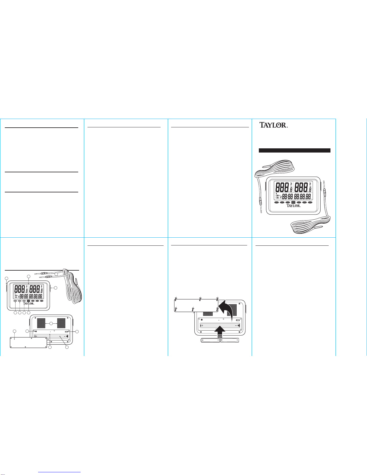
6. There is one three-position slide switch inside the battery
compartment. The user can enable the probe by selecting
the position of the switch. When the switch is in the “L”
position, the left probe is working and the right sensor
buttons are functionless. When the switch is in the “R”
position, the right probe is working and the left sensor
buttons are functionless. When the switch is in the middle
position, both probes are working and all buttons are
functional. The probe should be plugged into the unit all
the time as long as it is enabled. Position of the slide switch
should be in the correct position before battery is installed.
Changing the slide switch position requires resetting the
unit by re-installation of battery or pressing the system reset
button, which is also inside the battery compartment.
7. If the probe is enabled (through the slide switch) and is
unplugged during unit powering up or setup, the alarm will
beep and EEE will be displayed in the corresponding probe
temp display area. The unit cannot be set up until the
probe is plugged in again.
8. During normal operation, when the probe is unplugged,
the EEE temp and duration of the probe being unplugged
will be recorded. The alarm will beep during the probe is
unplugged. After the probed is inserted again, the
operation for that probe resumes.
9. During the time the probe is plugged-in or unplugged, the
temperatures recorded at that moment may not be
accurate. If these temperatures meet the temp high/low
settings, they will be written to the alarm records (together
with the “EEE” alarm record), and the users need to filter
out these un-accurate temperature records themselves.
10. The "Password Reset" button is inside the battery
compartment. Pressing the button once will reset the
password to “88:88”.
11.The “System Reset” button is inside the battery
compartment. The user can reset the unit any time for re-
initialization of the unit or in case the unit does not start up
after installation of the batteries. After this button is pressed,
the unit will go through the normal power up initialization
process, and all settings have to be re-entered. Only the old
alarm records (if there is any) can be retrieved after system
reset. The operator may use a paper clip or similar type of
object for accessing the system reset button.
Note: Old alarm records may be retrieved after hitting
System Reset button, but when alarm settings are re-
entered old records will be deleted.
1. All LCD segments are displayed for 3 seconds and the alarm
sounds for 1 second.
2. Then, current temperature(s) is displayed (default is °F), left
hand side of the bottom line displays “88:88”, right hand
side of the bottom line displays a flashing “00H00M00S”.
3. The unit enters the clock setting mode (flashing
00H00M00S). Press “UP/DOWN” buttons for Hour setting.
Pressing down the “UP/DOWN” buttons for more than 3
seconds activates the fast forward function. Press the “SET”
button to confirm the Hour setting. Hour digits stop flashing
and the remaining Minute and Second digits continue to
flash. Press “UP/DOWN” buttons for Minute setting.
Pressing down the “UP/DOWN” buttons for more than 3
seconds activates the fast forward function. Press the “SET”
button to confirm the Minute setting. Hour and minute digits
stop flashing and the remaining Second digits continue to
flash. Press “UP/DOWN” buttons for Second setting.
Pressing down the “UP/DOWN” buttons for more than 3
seconds activates the fast forward function. Press the “SET”
button to confirm the Second setting. The clock digits stop
flashing and start to tick. Left or right or both sides buttons
can be used for clock setting depending or which probe(s) is
enabled.
4. After the clock is set, the unit enters the password setting
mode (flashing “88:88”). Left or right or both sides buttons
can be used for setting depending or which probe(s) are
enabled.
(I) Press the “Up” or “Down” button for selecting the number
from 0~9 for first digit (the first press of “Down” changes
the digit from 8 to 7; the first press of up changes the digit
from 8 to 9). For example, 5 is selected. Pressing the “Set”
button again confirms 5, and the other three segments will
remain flashing.
(ii) Press the “Up” or “Down” button for selecting the number
from 0~9 (ex.4 is to be selected), press the “Set” button
again confirms 4, and the other two segments will remain
flashing.
(iii) Press the “Up” or “Down” button for selecting the number
from 0~9 (ex.3 is to be selected), press the “Set” button
again the 3 is confirmed and the last 8 still flashing.
(iv) Press the “Up” or “Down” button for selecting the number
from 0~9 (ex.2 is to be selected),press the “Set” button
again the 2 is confirmed and the Password “54:32” is set.
(v) The password display will show the set status of the probes:
“Set0” meaning that none of the probes is set. After the
password is set, the user can lock the unit by pressing the
“PASSWORD” button once. When the unit is locked, the
“LOCK” icon on the display will be turned on to indicate that
password has to be re-entered again for accessing the unit.
(vi) After the unit is locked, the user has to enter the password
to access the unit. Press the “PASSWORD” once, flashing
“88:88” appears on the left hand side of the bottom line.
Enter the password by following the set password procedure.
If the password is correct, the password will stop blinking
after the last digit entry and the display will revert to
“SetL/R/2/0”. All buttons are available at this time.
Otherwise, the password will just keep blinking and the
password entry process has to re-start again from the first
password digit.
(vii) The default password of the unit is “88:88”, the first
change of the password will be recorded as the new
password. In case the password is forgotten, the user has to
open the battery door and press the “Password Reset”
button on the battery compartment and the password will be
restored to the default password of “88:88”. The user can
then access the unit with the default password “88:88”. To
set a new password, the user has to reset the unit or re-
install the battery. The unit will start the whole setup process
after system reset or battery re-installation. All previous
settings will be lost except that the old alarm event records
are still retrievable. The high / low alarm set points and
delays are reset to the default values. The alarm
temperatures and/or the delay time should not be set for old
alarm records retrieval as new alarm settings will clear the
old alarm memory contents. The old alarm records will only
be cleared after the alarm temperatures and delay setting is
complete. The unit will quit the alarm setting mode
automatically during the alarm setting process if there is no
button pressed for 1 minute. This way the old alarm records
are preserved.
5. Once the clock and password are set, the unit enters the
normal display mode. The status of the probe setting is
displayed on the left hand bottom line of the LCD as “Set0”,
“Setr”, “SetL”, or “Set2”. The user can enter the set high /
low alarm events mode or scroll alarm events mode from
the normal display mode. If the user does not set the high /
low alarm set points, the unit will not record any alarm
events and will just display the current temperatures.
(i) Set High/Low Alarm set point:
a. The default high/low alarm set points are 40.0°F and 32.0°F
respectively while the default delay time is 00H00M00S for
both high and low alarms.
b. To set the alarm set points and corresponding delay times,
press down the “SET” button on Left or Right side for 3
seconds, the corresponding temperature display will display
the default high (40.0°F) or previous high alarm set point
The digit behind the decimal displays “H” and the left hand
side of the bottom line displays “Set” and a flashing “R” or
“L” indicating that the right or left probe is being set.
Increase or decrease the high alarm set point by pressing
the “UP” or “DOWN” key. When the “UP” or “DOWN”
key is pressed for more than 3 seconds, the fast forward
function is activated. When the desired high alarm set point
is reached, press the “SET” button to confirm high alarm set
point and the high alarm set point stops flashing. Then
“00H00M00S” or the previous high alarm delay starts
flashing on the right hand side of the bottom line for delay
time setting. Press “UP/DOWN” buttons for Hour setting.
Pressing down the “UP/DOWN” buttons for more than 3
seconds activates the fast forward function. Press the “SET”
button to confirm the Hour setting. Hour digits stop flashing
and he remaining Minute and Second digits continue to
flash. Press “UP/DOWN” buttons for Minute setting.
Pressing down the “UP/DOWN” buttons for more than 3
seconds activates the fast forward function. Press the “SET”
button to confirm the Minute setting. Hour and minute digits
stop flashing and the remaining Second digits continue to
flash. Press “UP/DOWN” buttons for Second setting.
Pressing down the “UP/DOWN” buttons for more than 3
seconds activates the fast forward function. Press the “SET”
button to confirm the Second setting. The alarm delay time
stops flashing. At this point, the high alarm set point and
delay are set.
c. The temperature display then displays the flashing default
(32.0°F) or previous low alarm set point, and the digit
behind the decimal will display “L”. Increase or decrease
the value by pressing the “UP” or “DOWN” button. When
the “UP” or “DOWN” button is pressed down for more
than 3 seconds, the fast forward function is activated. When
the desired low alarm set point is reached, press the “SET”
button again to confirm the low alarm set point and the low
alarm set point stops flashing. (Note: the low alarm set
point must be smaller than the high alarm set point.
Otherwise the low alarm set point will keep flashing after
the “SET” button is pressed for low alarm set point
confirmation.) Then “00H00M00S” or the previous low
alarm delay starts flashing on the right hand side of the
bottom line for low alarm delay setting. Press “UP/DOWN”
buttons for Hour setting. Pressing down the “UP/DOWN”
buttons for more than 3 seconds activates the fast forward
function. Press the “SET” button to confirm the Hour
setting. Hour digits stop flashing and the remaining Minute
and Second digits continue to flash. Press “UP/DOWN”
buttons for Minute setting. Pressing down the “UP/DOWN”
buttons for more than 3 seconds activates the fast forward
function. Press the “SET” button to confirm the Minute
setting. Hour and Minute digits stop flashing and the
remaining Second digits continue to flash. Press
“UP/DOWN” buttons for Second setting. Pressing down the
“UP/DOWN” buttons for more than 3 seconds activates the
fast forward function. Press the “SET” button to confirm the
Second setting. The alarm delay time stops flashing. At this
point, the low alarm and its delay time are set.
d. Once the high / low alarm and delays are set, the left hand
side of the bottom line displays “Set” “R” or “L” indicating
that the right or left probe is already set. The display then
returns to the normal display of current temperature, the
clock, and “Set” “R” or “L” or “2”.
e. Repeat the above setting procedure for another probe when
appropriate. If both probes are set, the normal display
should show the current temperature of both probes, the
clock, and “Set2”.
When the temperature is over the high point or below the low
point, the alarming events are recorded. There are maximum
96 Hours alarm history stored in memory. In the normal display
mode, press the “SET” button once to display the last alarm
event.When the current displayed alarm event is the last one,
pressing “UP””will scroll the alarm event back to the oldest
alarm event.For example, if the oldest alarm event is D0 R:
14:15 A 40°F (high temperature alarm occurred on the current
day at 14:15). Pressing the “UP” button once displays D0 R:
14:16 44°F (the maximum temperature recorded during alarm
period was 44°F at 14:16).
Pressing the “UP” button again will display D0 R: 14:18
00h02m33s (the temperature went back into safe range at
14:18, and the duration of the alarm was 2 minutes, 33
seconds). Pressing the “UP” button again will move to next
record.Pressing and holding the “UP” button for 3 seconds
activates the fast forward function. The alarm events are scrolled
backward by pressing the “DOWN” button once. Pressing and
holding the “DOWN” button for 3 seconds activates the fast
backward function. The last displayed alarm record will stay on
the display for 15 seconds. After 15 seconds the normal display
(current temperature, “Set” “R/L/2/0”, Clock) is resumed.
Once in the alarm events display mode, the only way to exit to
the normal display mode is to wait for the 15 seconds alarm
event time out or when a new alarm event arrives. The
temperature display for the corresponding probe should be
blank or only displaying the temperature data associated with
the alarm record when in alarm events display mode. The set
high / low alarm function is disabled in the alarm events display
mode, i.e. even though the user presses the “SET” for 3
seconds, the unit will not enter the alarm events set mode.
When there is no alarm records, “nr” (no records) will be
displayed on the lower left line of display when the “SET” button
is pressed (clock is still displayed on the lower right line).
Normal display mode is resumed after the 10 seconds alarm
events display time-out time.
The alarm records can't be deleted, unless new alarming set
points are set. It always keeps maximum 96 hours records in the
memory. The oldest alarm record will be replaced by the new
one when the memory is full.
When the new high and/or low alarm value is set, the memory
will clear all the records and start to record the new alarming
date from zero.
There are total 120 alarm records, 60 alarm records per probe.
Example of alarm records:
Initial settings: High alarm = 40.0°F
Low alarm = 32.0°F
High alarm delay = 20 minutes
Low alarm delay = 30 minutes
D3HL 6:35 39.1°F (high of the day was 39.1°F at 6:35:20am, 39.1°F is displayed in temperature
display screen)
D3LL 17:22 37.0°F (low of the day was 37.0°F at 5:22:45pm, 37.0°F is displayed in temperature
display screen)
D2HL 5:15 38.6°F (high of the day was 38.6°F at 5:15:00 am, 38.6°F is displayed in temperature
display screen)
D2LL 12:01 33.0°F (low of the was 33.0°F at 12:01:30pm, 33.0°F is displayed in temperature
display screen)
D1 L 14:00 A 40.0°F (at 2:00:15 pm temperature went above 40.0°F, 40.0°F is displayed in
temperature display screen)
At 14:20 the audible alarm starts beeping.
D1 L 14:30 50.0°F (high temperature for the alarm is 50.0°F at 2:30:30pm, 50.0°F is displayed in
temperature display screen)
D1 L 14:40 00h40m15s (temp went back below 40°F at 2:40:30pm after 40minutes and 15
seconds of being out)
D1 L 14:45 Usr (user stops alarm at 2:45:55pm and changes temperature unit from °F to °C)
D1 L 18:00 b0.0°C (at 6:00:23pm temperature went below 32.0°F, 0.0°C is displayed in
temperature display screen)
D1 L 18:05 –0.6°C (low temp for the alarm is 30.9°F at 6:05:01 pm, -0.6°C is displayed in
temperature display screen)
At 18:30 the audible alarm starts beeping.
D1 L 20:00 US r (user stops alarm at 8:00:59pm and changes temperature unit from °C to °F)
D1 L 20:10 2h09m42s (temp went back above 32°F at 8:10:05pm after 2 hours and 9 minutes 42
seconds of being out)
D1 L 21:00 b32°F (at 9:00:00pm temp went below 32 degrees, 32°F is displayed in temperature
display screen)
D1 L 21:01 29.0°F (the low temp for the alarm is 29.0°F recorded at 9:01:08pm, 29.0°F is
displayed in temperature display screen)
D1 L 21:02 00h02m30s (Temp went back above 32.0°F at 9:02:30pm after 2 minutes and 30
seconds of being out)
D1HL 14:30 50.0°F (high of the day was 50 degrees at 2:30:30pm, 50°F is displayed in
temperature display screen)
D1LL 21:01 29.0°F (low of the day was 29 degrees at 9:01pm, 29.0°F is displayed in temperature
display screen)
Between "D1 L 14:00 A40.0°F" & "D1 L 14:30 50.0°F" I would put a note saying that at 14:20 the
audible alarm starts beeping.
Between "D1 L 18:05 -0.6°C" & "D1 L 20:00 US r" I would put a note saying that at 18:30 the
audible alarm starts beeping.
Between "D0 L 10:00 A40.0°F" & "D0 L 10:30 45.3°F" I would put a note saying that at 10:20 the
audible alarm starts beeping.
D0 L 10:00 A40.0°F (at 10:00:05 am temperature went above 40 degrees, 40.0°F is displayed in
temperature display screen)
At 10:20 the audible alarm starts beeping.
D0 L 10:30 45.3°F (high temperature for the alarm is 45 at 10:30:01am, 45.3°F is displayed in
temperature display screen)
D0 L 11:40 1h40m43s (temp went back below 40 at 11:40:48am after 1 hour 40minutes 43
seconds of being out)
D0 L 12:00 b32.0°F (at 12:00:00 am temperature went below 32.0°F, 32.0°F is displayed in
temperature display screen)
D0 L 12:00 US r (user stops alarm at 12:00:59pm)
Note: Unit of temperatures records displayed is the current selected temperature unit
regardless of the temperature unit when the record was taken. For example, the unit of
temperature was °C when the unit recorded an alarm event, and that alarm event is
displayed in °F when the current temperature unit is °F and the alarm record is being
scrolled back.
Alarm Records
Alarm Records Cont.
Alarm Record Format
Example Alarm Record Format: