TE Connectivity IEC62196-2 I User guide

Application
Specification
114-94163-1
09APR2018 Rev C
Class 1
1
©2011 Tyco Electronics Corporation, a TE Connectivity Ltd. Company
All Rights Reserved
| Indicates Change
1 of 21
*Trademark. TE Connectivity, TE connectivity (logo), and TE (logo) are trademarks. Other logos, product and/or Company names may be trademarks of their respective owners.
LOC B
VEHICLE CHARGE INLET acc.
IEC62196-2 Type I / SAE 1772
Fahrzeugladedose gemäß
IEC62196-2 Typ I / SAE 1772

114-94163-1
Rev C
2 of 21
Content / Inhaltsverzeichnis
1. SCOPE / Anwendungsbereich..........................................................................................................3
1.1 Content / Inhalt...............................................................................................................................3
1.2 Processing Note / Verarbeitungshinweis......................................................................................3
2. APPLICABLE DOCUMENTS / Anwendbare Unterlagen.................................................................3
2.1 TE Connectivity Documents / TE Connectivity Unterlagen.........................................................3
2.2 General Documentation / Allgemeine Unterlagen........................................................................5
3. Application Tools / Verarbeitungswerkzeuge.................................................................................6
4. ASSEMBLY INSTRUCTIONS / Verarbeitungsrichtlinie ...................................................................7
4.1 Assembly overview / Baugruppenübersicht .................................................................................7
4.2 Parts to order / Bestellteile............................................................................................................8
4.3 Security Advice / Sicherheitshinweis ............................................................................................9
4.4 Assembly Steps / Montageschritte..............................................................................................10
4.5 End of Line Test / Endprüfung ....................................................................................................20
Only the German version is authoritative
Maßgebend ist nur der deutsche Text

114-94163-1
Rev C
3 of 21
1 SCOPE / ANWENDUNGSBEREICH
1.1 Content / Inhalt
This specification describes the handling and assembly of the vehicle charge inlets Typ I acc.
IEC 62196 for conductive charging of electric vehicles. This specification applies to manual
assembly of the components from series production tooling. The usage of multicore wire
sealing in the charge inlet is described.
For single wire cabling of the charge inlet the specification 114-94260-1 has to be applied.
Diese Spezifikation beschreibt die Verarbeitung der Fahrzeugladedosen Typ I nach IEC 62196 zum
konduktiven Laden von Elektro- und Hybridfahrzeugen. Diese Spezifikation ist für die Handmontage
der Teile aus Serienproduktionswerkzeugen anzuwenden. Es ist die Verarbeitung von mehradrigen
Leitungen in der Ladedose beschrieben.
Bei Einzelader-Verkabelung der Ladedose ist die Spezifikation 114-94260-1 anzuwenden.
1.2 Processing Note / Verarbeitungshinweis
The processor is responsible for ensuring the quality of the manufacturing process and the
proper function of the system. The warranty and liability is excluded if quality deficiency or
damages occur by failing compliance to this specification or using not specified, not released
tools, cables and components.
Für die Sicherstellung der Qualität des Produktes und des Verarbeitungsprozesses trägt ausschließlich
der Verarbeiter die Verantwortung, sowie für die spezifikationsgemäße Funktion des Systems.
Die Gewährleistung und Haftung ist ausgeschlossen, sofern durch Nichtbeachtung dieser
Verarbeitungsspezifikation Qualitätsmängel oder Schäden entstehen. Ferner bei Verwendung von hier
nicht aufgeführten, freigegebenen Verarbeitungswerkzeugen, nicht spezifizierten Leitungen und
Komponenten.
2 APPLICABLE DOCUMENTS / ANWENDBARE UNTERLAGEN
The following technical documents, if referred to, are part of this specification. In case of a
contradiction between this specification and the product drawing or this specification and the
specified documentation then the product specification has priority.
Die nachfolgend genannten Unterlagen, sofern darauf verwiesen wird, sind ein Teil dieser
Spezifikation. Im Falle des Widerspruches zwischen dieser Spezifikation und der Produktzeichnung
oder des Widerspruches zwischen dieser Spezifikation und den aufgeführten Unterlagen hat die
Produktspezifikation Vorrang.
2.1 TE Connectivity Documents / TE Connectivity Unterlagen
a) Customer drawings for Type 1 / Kundenzeichnungen für Typ 1
114-94163-1
CHARGE INLET, IEC62196-2 Type 1
Ladeschnittstelle IEC62196-2 Typ 1
2177804
ACTUATOR, LOCKING UNIT, ASSY
ZSB Aktuator mit Halter und Notentriegelungshebel
2177790
CABLE FIXATION, TE, Cover Inlet
Kabelabgang UT

114-94163-1
Rev C
4 of 21
2177791
INSULATION COVER, TE, Cover Inlet
Kabelabgang OT
2177861
FAMILY SEAL, MIXED
Familiendichtung
1241473
Screw 3x20mm
Schraube 3x20mm
2177797
O-Ring 3x1,5
O-Ring 3x1,5
2177798
5POS, MIXED, HSG, IEC62196-2 Type 1
Ladedose Typ 1
2177799
2.LOCK, TE, IEC62196-2 Type 1
Sekundärverriegelung / Steckgesicht Typ 1
2177815
PIN DIA 3.6, L/N, ASSY
ZSB L, N Pin
2177817
PIN DIA 2.8, PE
Pin PE
2177818
PIN DIA 1.5, CP/CS
Pilot / Proxy Pin
2236040
CONTACT CLAMP R5
Kontaktkralle R5
2236766
CODING RESISTOR R5
Kodierwiderstand R5
2287070
LABEL, TE, for Charge Inlet
Label, TE, für Ladedose

114-94163-1
Rev C
5 of 21
2.2 General Documentation / Allgemeine Unterlagen
a) Cable Specifications of Prescribed Cables / Leitungsspezifikation der vorgeschriebenen Leitungen
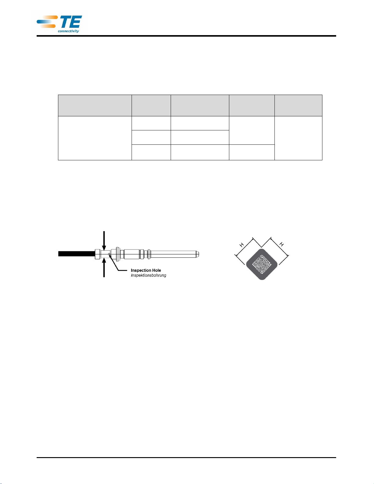
Cross-section / Querschnitt 2 x 4,0mm²
Supplier / Lieferant: Gebauer & Griller Kabelwerke GmbH
Outer Diameter / Außendurchmesser 10,1 -0,6 mm
Cable description / Leitungsbezeichnung: FLR31YBC11Y 2x4,0 (0,20) /T125 / 3
Gebauer & Griller Part No.: / Teile-Nr.: 125865
Supplier / Lieferant: Kromberg & Schubert GmbH
Outer Diameter / Außendurchmesser 10,1 -0,6 mm
Cable description / Leitungsbezeichnung: FLR32Y-(ST)CB11Y 2x4,0mm² (0,20)
Kromberg & Schubert Part No.: / Teile-Nr.: 64995730 Issue 4
Cross-section / Querschnitt 2 x 6,0mm²
Supplier / Lieferant: Gebauer & Griller Kabelwerke GmbH
Outer Diameter / Außendurchmesser 11,7 -0,6 mm
Cable description / Leitungsbezeichnung: FLR31YBC11Y 2x6,0 (0,20) /T125 / 3
Gebauer & Griller Part No.: / Teile-Nr.: 125866
Supplier / Lieferant: Kromberg & Schubert GmbH
Outer Diameter / Außendurchmesser 11,7 -0,6 mm
Cable description / Leitungsbezeichnung: FLR32Y-(ST)CB11Y 2x6,0mm² (0,20)
Kromberg & Schubert Part No.: / Teile-Nr.: 64995731 Issue 3
Cross-section / Querschnitt 1 x 4,0mm²
Supplier / Lieferant: LEONI Kabel GmbH
Outer Diameter / Außendurchmesser 3,7 -0,3 mm
Cable description / Leitungsbezeichnung: FLRY 4,0-B acc. / nach ISO6722; GS95007-1
Part No.: / Teile-Nr.: 76783111
Cross-section / Querschnitt 1 x 6,0mm²
Supplier / Lieferant: LEONI Kabel GmbH
Outer Diameter / Außendurchmesser 4,3 -0,3 mm
Cable description / Leitungsbezeichnung: FLRY 6,0-B acc. / nach ISO6722; GS95007-1
Part No.: / Teile-Nr.: 76783121
Cross-section / Querschnitt 2 x 0,75 (+0.75)mm²
Supplier / Lieferant: Gebauer & Griller Kabelwerke GmbH
Outer Diameter / Außendurchmesser 4,7 +/ 0,2 mm
Cable description / Leitungsbezeichnung: FLRYBY 2 x 0.75 (+ 0.75) acc. / nach ISO6722;
GS95007-1
Part No.: / Teile-Nr.: -

114-94163-1
Rev C
6 of 21
3 APPLICATION TOOLS / VERARBEITUNGSWERKZEUGE
Required application tools are / Benötigte Verarbeitungswerkzeuge sind:
Application Parts
Verarbeitungselemente
Wire Size
Leitungs-
querschnitt
Crimp Hight H
Crimphöhe H
Die Set Nr.:
Matritze-Nr:
Tool Nr.:
Anschlag-WZ-
Nr
Pin Contact
Stift Kontakt
4,0mm²
2,81mm +/-0,05
1-1105852-8
1-1105850-8
0,75mm²
1,90mm +/-0,05
6,0mm²
3,58mm +/-0,05
2-1105870-8
Table / Tabelle 1
The crimp height has to be measured over both parallel faces. Both dimensions have to be in
tolerance (figure 1).
Die Crimphöhe ist über die jeweils parallelen Flächen zu messen. Beide Maße müssen innerhalb der
geforderten Toleranz liegen (Bild 1).
Figure / Bild 1

114-94163-1
Rev C
7 of 21
4 ASSEMBLY INSTRUCTIONS / VERARBEITUNGSRICHTLINIE
4.1 Assembly overview / Baugruppenübersicht
Figure / Bild 2
Charge Inlet Type I / Ladedose Typ I

114-94163-1
Rev C
8 of 21
4.2 Parts to order / Bestellteile
Charge Inlet Typ I / Ladedose Typ I
L/N + Earth:
4,0 mm²
Signal 0,75mm²
L/N + Earth:
6,0 mm²
Signal 0,75mm²
Wire Size
Leitungsquerschnitt
Part
Teil
Pos.
Qty.
Name / Bezeichnung
P/N
1
1
5POS, MIXED, HSG, IEC62196-2 Type 1
Ladedose Typ 1
0-2177798-1
2
1
2.LOCK, TE, IEC62196-2 Type 1
Sekundärverriegelung / Steckgesicht Typ 1
0-2177799-1
3
1
ACTUATOR, LOCKING UNIT, ASSY
ZSB Aktuator
9-2177804-1 or
1-2177804-1
4
1
CABLE FIXATION, TE, Cover Inlet
Kabelabgang UT
0-2177790-1
5
1
INSULATION COVER, TE, Cover Inlet
Kabelabgang OT
0-2177791-1
6
2
FAMILY SEAL, MIXED, Vers.1
Familiendichtung, Version 1
9-2177861-1
7
3
Screw 3x20mm
Schrauben für Aktuator
1-1241473-4
8
2
PIN DIA 3.6, L/N, ASSY
ZSB L, N Pin
9-2177815-2
9-2177815-3
9
1
PIN DIA 2.8, PE
Pin PE
9-2177817-2
9-2177817-3
10
2
PIN DIA 1.5, CP/CS
Pilot / Proxy Pin
9-2177818-2
11
5
O-Ring 3x1,5
O-Ring 3x1,5
9-2177797-1
12
1
Coding Resistor 2.7kΩ
Codierungswiderstand 2.7kΩ
0-2236766-1
13
2
Contact Kit R5, Inlet Type I
Kontaktkralle R5, Inlet Typ 1
0-2236040-1
14
1
NTC, Temperature Sensor (Optional) 2)
NTC Temperatursensor (optional) 2)
0-2282093-1
15
1
Label, TE, for Charge Inlet
Label, TE, für Ladedose
0-2287070-1 1)
1) Label blank, to be printed with defined information, applicable on Insulation Cover
Label blank, zu bedrucken mit vorgegebener Information, applizierbar auf Kabelabgang OT
2) Cabling of the temperture sensor is not reflected in mentioned family seal (pos.6). Needs to be defined separately
and may require particular sealing
Verkabelung des Termperatursensors wird von der genannten Family Seal (Pos.6) nicht berücksichtigt.
Verkabelung muss separat bewertet werden und kann eine spezielle Abdichtung erfordern.
Table / Tabelle 2

114-94163-1
Rev C
9 of 21
4.3 Security Advice / Sicherheitshinweis
The assembly should only be performed by trained personnel.
Die Montage ist nur von geschultem Personal durchzuführen.
Avoid prolonged or repeated skin contact with silver plating (wear protective gloves)!
Länger andauernden / wiederholten Hautkontakt mit den versilberten Oberflächen vermeiden
(Schutzhandschuhe tragen)
ATTENTION!
- HIGH VOLTAGE APPLICATION -
CABLE INSULATION MUST NOT BE DAMAGED!
ACHTUNG !
- HOCHSPANNUNGSANWENDUNG -
LEITUNGSISOLATION DARF NICHT BESCHÄDIGT
WERDEN!

114-94163-1
Rev C
10 of 21
4.4 Assembly Steps / Montageschritte
The assembly is shown for Type I Vehicle Charge Inlets. The assembly shall be done by trained
personnel only!
Die Assemblage ist dargestellt für Typ I Fahrzeugladedosen. Die Assemblage darf nur durch geschultes
Personal erfolgen!
Step 1 / Schritt 1
Cut wires of Resistor acc. figure 3. Place the resistor R5 into the receptacle on the backside of the
charge inlet (figure 4). Lay then the two Contact Kit R5 over the resistor and press them down to
end position to contact the resistor on both sides (figure 5).
Requirements for Resistor:
- Resistor Type/Size MBB/SMA 0207, dimensions acc. figure 3
- Wires tin plated
- Climatic Category (LCT/UCT/days): 55/155/56
- Acc. Spec. EN 140101-
- AEC-Q200 qualified
- Resistance value 2700Ω±1%
Den Widerstand R5 in die entsprechende Aufnahme auf der Rückseite der Ladedose legen (Bild 4). Dann
die beiden Kontaktkrallen über dem Widerstand platzieren und vollständig herunterdrücken um den
Widerstand beidseitig zu kontaktieren (Bild 5).
Anforderungen an den Widerstand:
- Typ/Größe MBB/SMA 0207; Abmessungen nach Bild 3
- Drähte verzinnt
- Klimakategorie (LCT/UCT/days): 55/155/56
- nach Spezifikation EN 140101-806
- AEC-Q200 qualifiziert
- Widerstandswert 2700Ω ±1%
Figure / Bild 3

114-94163-1
Rev C
11 of 21
Figure / Bild 4
Figure / Bild 5
Step 2 / Schritt 2
Assemble the Cable Fixation 2177790 to the charge inlet at the required angle (acc. Drawing 114-
94163-1) by pressing the ring of the cable fixation into the related collar of the housing. Care shall
be taken of a homogenous force application on the Cable Fixation Ring. All hooks have to be
engaged properly (Figure 6).
Den Kabelabgang UT 2177790 an die Ladedose in benötigtem Winkel (gemäß Zeichnung 114-94163-1)
montieren, indem der Ring des Kabelabgangs UT in den zugehörigen Kragen des Ladedosengehäuses
gepresst wird. Dabei ist eine homogene Kraftaufbringung auf den Ring des Kabelabgangs UT sicher zu
stellen. Alle Haken müssen vollständig eingerastet sein (Bild 6).

114-94163-1
Rev C
12 of 21
Figure / Bild 6
Step 3 / Schritt 3
The family seal 2177861 must be placed into the CABLE FIXATION 2177790 and into the
INSULATION COVER 2177791. Ensure correct orientation of the seal (Figure 7).
Die Familiendichtungen 2177861 sind in die Teile Kabelabgang UT 2177790 und Kabelabgang OT
2177791 einzulegen. Auf korrekte Orientierung ist zu achten (Bild 7).
Figure / Bild 7

114-94163-1
Rev C
13 of 21
Step 4 / Schritt 4
Remove outer isolation, shield and filler of Multicore Cables; length max. 40mm proposed.
ATTENTION: Any damage of the wire isolation has to be avoided!
Von den Mantelleitungen die äußere Ummantelung, den Schirm und Füller entfernen; Länge max. 40mm
empfohlen,
ACHTUNG: Dabei darf die Isolation der Einzelleitungen nicht beschädigt werden!
Step 5 / Schritt 5
Remove isolation of the single wires according figure 8 to following lengths:
Die Ummantelung der Einzelleitungen gemäß Bild 8 mit folgenden Längen entfernen:
Wire Size
Leitungsquerschnitt
Removal of isolation dim. "A"
Abisolierlänge "A"
0,75 mm²
8 +/-1 mm
4,0 mm²
8 +/-1 mm
6,0 mm²
8 +/-1 mm
Figure / Bild 8
Step 6 / Schritt 6
Crimp the conductors to the contact pins with the specified tools. Care shall be taken that all
braids are caught in the crimp. Not inserted braids may jeopardize HV requirements! Wires shall be
completely inserted to be visible through the inspection hole (Figure 9). Crimp height H shall be
conform to dimension acc. table 1.
Die Kontaktstifte auf die Einzeladern mit spezifiziertem Werkzeug crimpen. Dabei ist auf das Einstecken
und Vercrimpen sämtlicher einzelnen Leitungsdrähte zu achten. Nicht eingecrimpte Drähte können die HV
Anforderungen gefährden! Die Leitungsdrähte müssen komplett eingesteckt werden und durch die
Inspektionsbohrung sichtbar sein (Bild 9). Die Crimphöhe H muss der Vorgabe in Tabelle 1 entsprechen.
Figure / Bild 9

114-94163-1
Rev C
14 of 21
Step 7 / Schritt 7
Assemble the O-Rings on the Contact Pins (Figure 10). Take care of:
- max. allowable elongation 200%
- Distortion, twist not allowed
- Damage (e.g. cuts) not allowed
- Any kind of pollution is not allowed
Die O-Ringe auf den Kontaktstiften montieren (Bild 10), dabei dringend beachten:
- Max. zulässige Dehnung 200%
- Verdrehung ist nicht zulässig
- Beschädigungen (z.B. Anschnitte) sind nicht zulässig
- Verschmutzung ist nicht zulässig.
Figure / Bild 10

114-94163-1
Rev C
15 of 21
Step 7 / Schritt 7
Insert the Contacts from the backside into the Charge Inlet Housing according to the cavity
description (figure 11) into their locking position. To ensure that the contacts are correctly
inserted, pull and push with a low force on the cables (max. 10N) and check visually on the
frontside that the locking lances are properly engaged in the related pin groove. The locking
lances must not stay outside of the grooves (Figure 12). Ensure the O-Rings are properly
positioned in their seats and are not damaged!
Die Kontakte von der Rückseite entsprechend der Kammerbeschriftung (Bild 11) in das Kontaktgehäuse
bis zur Einrastposition einschieben. Zum Prüfen der Verrastung an der Leitung in und entgegen der
Steckrichtung ziehen bzw. drücken (max. 10N) und dabei die korrekte Verrastung der Rastlanzen in der
Rille der Stifte von der Vorderseite kontrollieren. Die Rastlanzen dürfen nicht außerhalb der Rillen stehen
(Bild 12). Dabei sicherstellen, dass die O-Ringe korrekt in ihren Sitzen positioniert sind und nicht
beschädigt wurden!
Figure / Bild 11
Backside / Rückseite Frontside / Vorderseite
Figure / Bild 12

114-94163-1
Rev C
16 of 21
Step 8 / Schritt 8
Place the cables at their particular position into the CABLE FIXATION 2177790 and secure them
with cable binders (Figure 13)
Wire PE/Earth Left cable exit
Single Wires L/N of Power Multicore Cable Centre cable exit
Single Wires of Signal Multicore Cable Right cable exit
Requirements for applied cable binders:
- Width 2.5mm - 3mm
- Heat Stabilized, Temperature range min. -40…+105°C
- Tensile Strength 80N min.
Die Leitungen an ihre jeweilige Position in den Kabelabgang UT 2177790 bringen und mit Kabelbindern
sichern (Bild 13).
Leitung PE/Erde
Linker Leitungsabgang
Einzeladern L/N der Power-Mantelleitung
Mittlerer Leitungsabgang
Einzeladern der Signal-Mantelleitung
Rechter Leitungsabgang
Anforderungen an die verwendeten Kabelbinder:
- Breite 2,5mm - 3mm
- Wärmestabilisiert, Temperaturbereich min. -40…+105°C
- Mindesthaltekraft/Zugfestigkeit min. 80N
Figure / Bild 13

114-94163-1
Rev C
17 of 21
Step 9 / Schritt 9
After the contacts have been controlled for correct positioning and locking, the Secondary Lock
has to be pressed in from the front side (figure 14). The adequate locking must be ensured and
checked (dimensional check of correct position, figure 14). The secondary lock has to be secured
with the screw from the backside (screwing torque 0,9 +/- 0,15 Nm) (figure 15).
ATTENTION: The correct pinning has to be ensured BEFORE locking the Secondary Lock!
Rewiring is not possible after locking the Secondary Lock without destroying the plastic parts.
Nachdem die Kammern bestückt und die Kontakte auf vorschriftsmäßigen Sitz geprüft wurden, muß die
Zweite Kontaktsicherung von vorne in das Ladedosengehäuse eingerastet werden (Bild 14). Das
ordnungsgemäße Verrasten muss sichergestellt und geprüft werden (Einpresstiefe in das Gehäuse, Bild
14). Die Zweite Kontaktsicherung ist mit der Schraube von der Rückseite zu sichern
(Anzugsdrehmoment 0,9 +/- 0,15 Nm)(Bild 15).
ACHTUNG: Die korrekte Kontaktbelegung ist VOR der Verrastung der Zweiten Kontaktsicherung sicher zu
stellen! Eine Änderung der Kontaktbelegung ist nach Verrastung der Zweiten Kontaktsicherung nicht mehr
ohne Zerstörung der Kunststoffteile möglich.
Figure / Bild 14
Figure / Bild 15

114-94163-1
Rev C
18 of 21
Step 10 / Schritt 10
Assemble the Temperature Sensors into the Charge Inlet (Figure 16) in the related cavities. Press-
in force may be applied on the brass collar ONLY. Push the sensor with the brass collar down to
the bottom of the housing.
CAUTION: Avoid damage of the cable exit of the temperature sensors and of the cables.
Die Temperatursensoren in die entsprechenden Kavitäten des Ladedosen Gehäuses montieren (Bild 16).
Eindrückkraft AUSSCHLIESSLICH auf den Messing-Kragen aufbringen! Über den Messing-Kragen die
Sensoren bis zur Bodenfläche des Gehäuses eindrücken.
ACHTUNG: Beschädigung des Leitungsausgangs am Temperatursensor sowie an den Leitungen
vermeiden!
Figure / Bild 16
Step 11 / Schritt 11
Assemble the Insulation Cover to the Charge Inlet (Figure 17). Ensure that all hooks are properly
engaged.
Den Kabelabgang OT an die Ladedose montieren (Bild 17). Auf sichere Verrastung aller Rastelemente
achten.

114-94163-1
Rev C
19 of 21
Figure / Bild 17
Step 12 / Schritt 12
Assemble the Connector Locking Unit to the charge interface. Ensure the prepositioning collar
engages properly into the charge interface housing and fix the locking unit with two screws,
torque 0,9 +/- 0,15 Nm (Figure 18).
Die Stecker Verriegelungseinheit auf das Ladedosengehäuse montieren. Dabei ist sicherzustellen, dass
der Vorführungs-Kragen korrekt in die Ladedose eingesetzt wird. Die Verriegelungseinheit mit den beiden
Schrauben verschrauben, Anzugsdrehmoment 0,9 +/- 0,15 Nm (Bild 18).
Figure / Bild 18

114-94163-1
Rev C
20 of 21
4.5 End of Line Test / Endprüfung
Assembled Charge Interfaces have to be tested electrically and mechanically to applicable
requirements, including High Voltage test.
As a minimum following tests have to be performed:
- Isolation Resistance:
Test Voltage: 500VDC pin-to-pin (all pins, excluding CP-to-CS)
Inspection Duration: 1s
min. Riso: 200MOhm
- Dielectric withstand voltage:
Test Voltage: 2000VAC pin-to-pin (all pins, excluding CP-to-CS)
Inspection Duration: 1s
max. Leakage current: 10mA
- Correct Pinning
- Check seals for correct seating / Check of leakage
- Gauge check of mating face
- Functionality of connector locking device (mechanical check of pin movement in locking and
unlocking position)
- Application of marking (label) according requirements
Alle Ladedosen müssen elektrisch und mechanisch entsprechend den Einsatzanforderungen geprüft
werden, inklusive Hochspannungstest.
Es sind zumindest folgende Prüfungen durchzuführen:
- Isolationswiderstand:
Prüfspannung: 500VDC von Stift zu Stift (zwischen allen Stiften, außer CP-zu-CS)
Prüfdauer: 1s
min. Isolationswiderstand: 200MOhm
- Spannungsfestigkeit:
Prüfspannung: 2000VAC von Stift zu Stift (zwischen allen Stiften, außer CP-zu-CS)
Prüfdauer: 1s
max. Leckstrom: 10mA
- Korrekte Pinbelegung
- Prüfung der Dichtungen auf korrekten Sitz / Dichtheitsprüfung
- Lehrenprüfung des Steckgesichtes
- Funktion der Steckerverriegelungseinheit (mechanische Prüfung der Stift Bewegung in Verriegelungs-
und Entriegelungs-Position)
- Anforderungskonforme Kennzeichnung (Label) aufbringen
This manual suits for next models
1
Table of contents
Other TE Connectivity Batteries Charger manuals
Popular Batteries Charger manuals by other brands

Pitaka
Pitaka Air Quad user manual

Hubbell
Hubbell USB1528 Series installation instructions

Dolphin
Dolphin 12V25A TECHNICAL NOTICE

Battery Doctor
Battery Doctor 23140 instruction manual

nedis
nedis NBARF9015FBK quick start guide

Phillips & Temro industries
Phillips & Temro industries EVOCHARGE iEVSE Installation guide & user manual

Central Park
Central Park CA8001 installation instructions

Motorola solutions
Motorola solutions PMPN4563 quick start guide

Wallbox
Wallbox DC Charger 1ph installation guide

Ericsson GE
Ericsson GE 19B801507P1 Maintenance manual

HEDBOX
HEDBOX RP-DC200 user manual

Dremel
Dremel 760 Operating/safety instructions