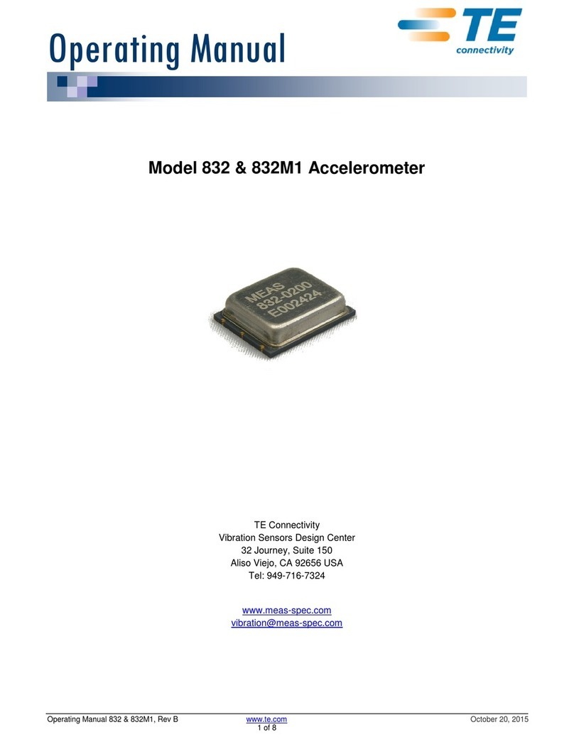
TE Connectivity 549 AC User manual

Installation and
Operating Instructions
549 AC Ammeter
AC ammeter for measuring single phase
current.
Introduction
The 549 Digital Ammeter is designed to accurately measure AC
RMS Current via a Current transformer. Measurements will be
displayed on an integral LCD. The compact design allows it to be
fitted in a standard 17/32 inch switch knock out. The product
harvests power from the input signal. No other power supply is
required to power this product.
This manual provides all the necessary instructions to safely
install and operate the instrument.
Front Panel Buttons
In measurement mode, the buttons control the displayed
measurement as follows:
Screen navigation
In set-up mode, this is the ‘Next‘ button.
Changes the highlighted value
(set-up mode only)
Setting up
The instrument has a default CT ratio setting of 5:5A. Before
operation the product MUST be set to the correct CT ratio.
The instrument is fitted with an internal battery which has a
limited life expectancy as it is only designed for commissioning
purposes, when battery powered pressing two buttons
simultaneously enters “Setup” mode. The Instrument will
automatically switch off after approximately 10 seconds of
inactivity. The battery supplies the programming function and
does not affect the overall operation of the instrument. If the
battery does become exhausted the setup mode can still be
accessed by passing a current between 10-100% of nominal
through the product.
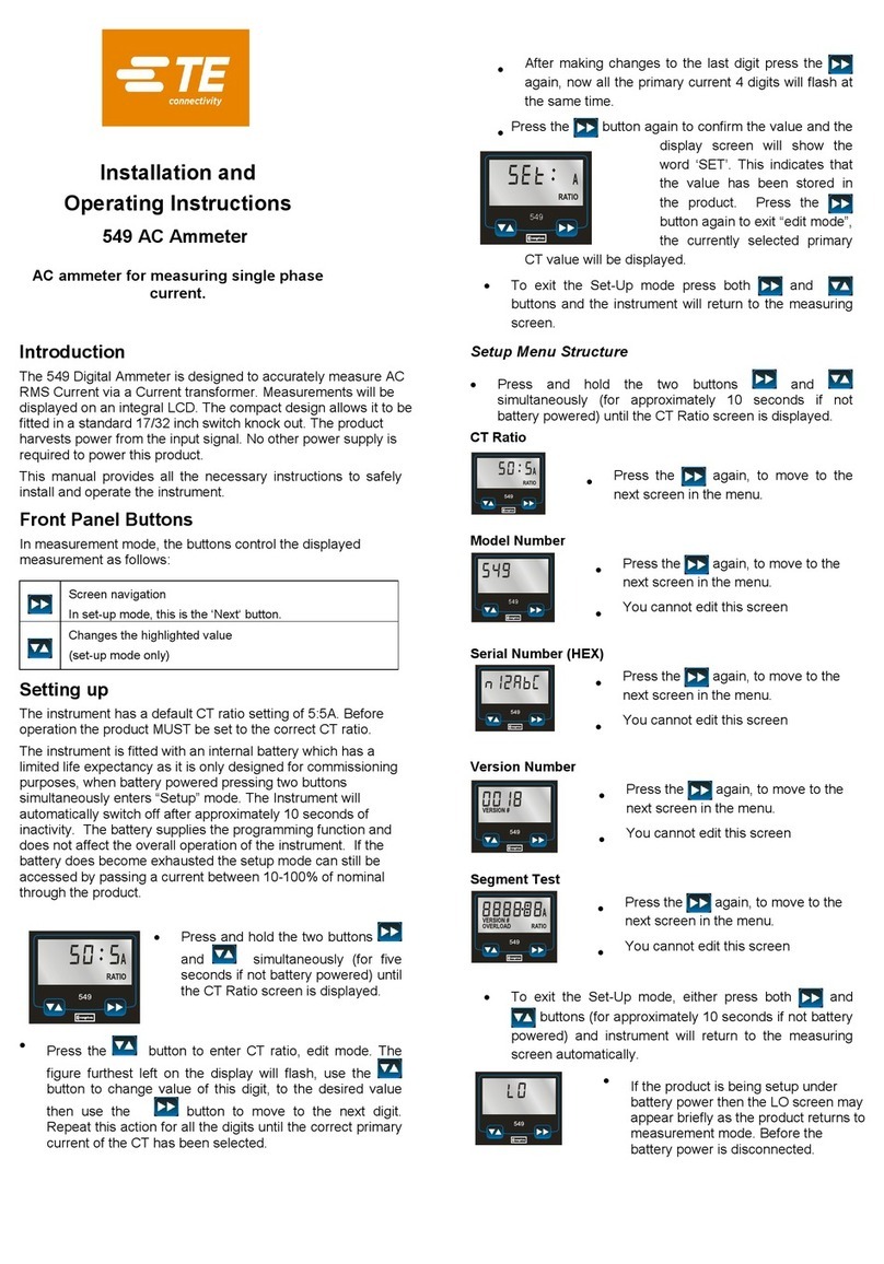
•Press and hold the two buttons
and simultaneously (for five
seconds if not battery powered) until
the CT Ratio screen is displayed.
•Press the button to enter CT ratio, edit mode. The
figure furthest left on the display will flash, use the
button to change value of this digit, to the desired value
then use the button to move to the next digit.
Repeat this action for all the digits until the correct primary
current of the CT has been selected.
•After making changes to the last digit press the
again, now all the primary current 4 digits will flash at
the same time.
•Press the button again to
confirm the value and the
display screen will show the
word ‘SET’. This indicates that
the value has been stored in
the product. Press the
button again to exit “edit mode”, the currently selected
primary CT value will be displayed.
•To exit the Set-Up mode press both and
buttons and the instrument will return to the measuring
screen.
Setup Menu Structure
•Press and hold the two buttons and
simultaneously (for approximately 10 seconds if not
battery powered) until the CT Ratio screen is displayed.
CT Ratio
•Press the again, to move to the
next screen in the menu.
Model Number
•Press the again, to move to the next screen in the
menu.
•You cannot edit this screen
Serial Number (HEX)
•Press the again, to move to the
next screen in the menu.
•You cannot edit this screen
Version Number
•Press the again, to move to the
next screen in the menu.
•You cannot edit this screen
Segment Test
•Press the again, to move to the
next screen in the menu.
•You cannot edit this screen
•To exit the Set-Up mode, either press both and
buttons (for approximately 10 seconds if not battery
powered) and instrument will return to the measuring
screen automatically.
•If the product is being setup under
battery power then the LO screen may
appear briefly as the product returns to
measurement mode. Before the
battery power is disconnected.
549
549

Installation
The unit may be mounted in a panel of any thickness up to a
maximum of 6mm (0·25in). Leave enough space behind the
instrument to allow for bends in the connection cables. As the
front of panel enclosure conforms to IP52, it is protected from
dripping water. The unit is intended for use in a reasonably
stable ambient temperature within the range -10 to +55°C. Do
not mount the unit where there is excessive vibration or in
excessive direct sunlight.
Safety
The unit is designed in accordance with BS EN 61010-1:2001
(IEC 61010-1:2001) – Permanently connected use, Normal
condition. Installation category III, pollution degree 2, basic
insulation for rated voltage. Measurement Category III.
EMC Installation Requirements
Whilst this unit complies with all relevant US EMC (electro-
magnetic compatibility) regulations, any additional precautions
necessary to provide proper operation of this and adjacent
equipment will be installation dependent and so the following can
only be general guidance:
•Avoid routing wiring to this unit alongside cables and
products that are, or could be, a source of interference.
•The signal to the unit should not be subject to excessive
interference. In some cases, a supply line filter may be
required.
•To protect the product against incorrect operation or
permanent damage, surge transients must be controlled. It
is good EMC practice to suppress transients and surges at
the source. The unit has been designed to automatically
recover from typical transients; however in extreme
circumstances it may be necessary to temporarily reduce the
magnitude of the measured signal to the point where the
instrument turns off for a period of greater than 10 seconds
to restore correct operation.
•It is good practice to install sensitive electronic instruments
that are performing critical functions in EMC enclosures that
protect against electrical interference causing a disturbance
in function.
Wiring
Input connections are made to terminals posts. Use cable lugs
suitable for 6-32 UNC screw. Wiring should conform to national
Electrical Code Class 1 and sized appropriate to CT secondary
current ratings.
The current inputs of this product are designed for
connection into systems via current transformers only.
Instrument transformers used for connection to the meter must
be of approved type and compliant with ANSI/IEEE C57.13 or
IEC 60044-1, selected and sized appropriate to the supply
network being monitored. CT secondaries must be grounded in
accordance with local regulations. It is desirable to make
provision for shorting links to be made across CT secondary’s to
permit easy replacement of a unit should this ever be necessary.
This instrument is intended for panel mounting. Terminals must
be enclosed within the panel. Terminal nuts should be tightened
to 8.0 lbs in (1.0Nm) only.
Earth/Ground Connections
For safety reasons, current transformer secondary connections
should be grounded in accordance with local regulations. Under
no circumstances should the product be operated without this
Earth connection.
Maintenance
In normal use, little maintenance is needed. As appropriate for
service conditions, isolate from electrical power, inspect the unit,
and remove any dust or other foreign material present.
Periodically check all connections for freedom from corrosion and
screw tightness, particularly if vibration is present.
The front of the case should be wiped with a dry cloth only. Use
minimal pressure, especially over the viewing window area. If
necessary wipe the rear case with a dry cloth. If a cleaning agent
is necessary, isopropyl alcohol is the only recommended agent
and should be used sparingly. Water should not be used. If the
rear case exterior or terminals should be contaminated
accidentally with water, the unit must be thoroughly dried before
further service. Should it be suspected that water might have
entered the unit, factory inspection and refurbishment is
recommended.
Contains no serviceable parts:
In the unlikely event of a repair being necessary, it is
recommended that the unit be returned to the factory or nearest
Crompton Instruments / TE Connectivity service centre.
This product contains a Lithium cell, and should be recycled or
disposed of in accordance with local environmental regulations.
Specification
Measurement Inputs
Nominal Input Current 5A AC RMS
Max. Continuous input Overload 6A AC RMS
Max. Short duration input Current 50A for 1 second.
Maximum VA Burden 3 VA
Frequency 60Hz +/- 2%
Maximum Total Harmonic Distortion 30%
Maximum Crest Factor 1.68
Range of Use
Values of measured quantities, components of measured
quantities, and quantities which affect measurement errors to
some degree, for which the product gives meaningful readings:
Current
1 … 120% of nominal
Ratio 5 … 2000A
Accuracy
Current (A) ± 1% of range
Warnings
•During normal operation, voltages hazardous to life
may be present at some of the terminals of this unit.
•Installation and servicing should be performed only
by qualified, properly trained personnel abiding by
local regulations.
•Ensure all supplies are de-energised before
attempting connection or other procedures.
•Terminals should not be user accessible after
installation and external installation provisions must
be sufficient to prevent hazards under fault
conditions.
•Never open-circuit the secondary winding of an
energized current transformer.
•This product should only be operated with CT
secondary connections Earthed.
•If this equipment is used in a manner not specified
by the manufacturer, protection provided by the
equipment may be impaired.
•If sufficient torque setting of 8.0Ibs in (1.0Nm) cannot
be applied to the rear fixing, the product should not
be installed.
Caution: Risk of
Electric Shock

A
B
C D H
E
I
J
K
in
mm
A
1.86
47.3
B
1.60
40 .8
C
0 .47
12.0
D
1.74
44.4
E
0 .70
17.8
F
0 .87
22.1
G
0 .99
12.0
H
0 .51
13.0
I
0 .16
4.0
J K
1.0 8
27.5
1.18
30 .0
PAN EL CUT-OU T 2
PAN EL CU T-O UT 1
D
A
E
B
C
(USE ADAPTOR RIN G)
AD APTO R RIN G
F
G
in
mm
A
1.20
30 .5
B
0 .57
14.5
C
0 .25
6.40
D
1.0 9
27.8
E
0 .15
3.9
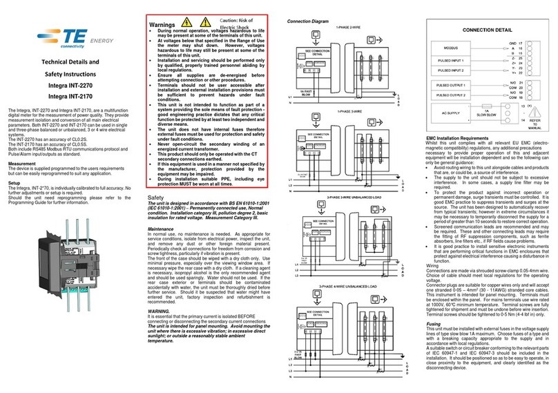
GU ID E N O TES FOR USIN G SUPPLIED FITTIN G KIT.
1) PLACE IN STRUM EN T IN PAN EL CUTOUT.
2) FIT AD APTOR RIN G , IF USIN G CUTOUT 1.
3) FIT RETAIN IN G RIN G, EN SURIN G TABS ARE ALIGN ED AS SHOW N .
(APPROX 45 DEGREE AN GLE RELATIVE TO GROOVES IN CASE)
4) IM PORTAN T - N UT 'A' IS USED FOR FACTORY ASSEM BLY ON LY AN D
M UST N OT BE TAM PERED W ITH D URIN G IN STALLATION .
5) FIT N UT 'B', EN SURIN G A N O M 3mm GAP IS LEFT BETW EEN IT AN D N UT 'A'
6) FIT W ASHERS PRIOR TO AN D AFTER CON N ECTION W IRES.
7) FIT N UT 'C'.
8) EN SURE N UT 'B' IS REFRAIN ED FROM M OVEM EN T.
9) N UT 'C' SHOULD N O W BE TIGH TEN ED.
RETAIN IN G RIN G
RETAIN IN G RIN G
AD APTOR RIN G
ABC
IM PORTAN T
SEE N OTES 4 - 9
Connection Diagram
N
L
Reference Conditions of Influence Quantities
Influence Quantities are variables that affect measurement errors
to a minor degree. Accuracy is verified under nominal value
(within the specified tolerance) of these conditions.
Ambient temperature 23°C ±2°C
Input waveform 60Hz ± 0.5%
Input waveform Sinusoidal
(distortion factor <0·005)
Magnetic field of external
origin Terrestrial flux
Environment
Operating temperature -10°C to +55°C
*
Storage temperature -30°C to +85°C
*
*
Maximum operating and storage temperatures are in the context
of typical daily and seasonal variation.
Relative humidity 0 to 95%, non-condensing
Altitude Up to 2000m
Vibration 10Hz to 50Hz, IEC 60068-2-6, 2g
Shock 30g in 3 planes
Mechanics
Dimensions 40.80x47.25x59.25mm (h x w x d)
1.60”x 1.86”x2.33” (h x w x d)
Depth (behind panel)
2.36” (60 mm) maximum
Case protrusion
(front of panel) 0.48” (12.2 mm) maximum
Sealing IP52 (front panel), IP30 (case) (minimum)
Approval, Certification, and Standards Compliance
EMC, Emissions FCC Part 15
Safety
UL
61010
-
1:2
nd
edition.
While TE Connectivity (TE) has made every reasonable effort to ensure the accuracy of the information in this catalogue, TE does not guarantee that it is error-free, nor does TE make any other
representation, warranty or guarantee that the information is accurate, correct, reliable or current. TE reserves the right to make any adjustments to the information contained herein at any time
without notice. TE expressly disclaims all implied warranties regarding the information contained herein, including, but not limited to, any implied warranties of merchantability or fitness for a
particular purpose. The dimensions in this catalogue are for reference purposes only and are subject to change without notice. Specifications are subject to change without notice. Consult TE
for the latest dimensions and design specifications. TE Connectivity and TE connectivity (logo) are trademarks. CROMPTON is a trademark of Crompton Parkinson Limited and is used under
licence. Other products or company names mentioned herein may be trademarks of their respective owners.
Tyco Electronics UK Ltd Registered office:
A TE Connectivity company Faraday Road, Dorcan
Freebournes Road, Swindon, SN3 5HH
Witham, CM8 3AH, UK Reg. No. 550 926
Tel: +44 (0) 1376 509509
Fax: +44 (0) 1376 509511
www.crompton-instruments.com
www.energy.te.com
Project 2208. Drawing No. CI-3K68901 Rev.K DMR 2777 28/02/13
Table of contents
Other TE Connectivity Measuring Instrument manuals

TE Connectivity
TE Connectivity DRS-100-3P User manual

TE Connectivity
TE Connectivity Challenger 361 Series User manual

TE Connectivity
TE Connectivity Integra Ri3 User manual

TE Connectivity
TE Connectivity 805M1 User manual

TE Connectivity
TE Connectivity Integra INT-2270 Owner's manual

TE Connectivity
TE Connectivity 832 User manual

TE Connectivity
TE Connectivity 549 User manual

TE Connectivity
TE Connectivity Integra INT-2270 User manual

TE Connectivity
TE Connectivity DRS-CT-3P-MOD-2T User manual

TE Connectivity
TE Connectivity M242-05 Series User manual