manuals.online logo
Brands
  1. Home
  2. •
  3. Brands
  4. •
  5. TE Connectivity
  6. •
  7. Power Tools
  8. •
  9. TE Connectivity SDE-SA User manual

TE Connectivity SDE-SA User manual

©2011 Tyco Electronics Corporation, a TE Connectivity Ltd. Company
All Rights Reserved
*Trademark
TE Connectivity, TE connectivity (logo), and TE (logo) are trademarks. Other logos, product and/or Company names may be trademarks of their respective owners.
1of 3
Instruction Sheet
TOOLING ASSISTANCE CENTER
1-800-722-1111
PRODUCT INFORMATION
1-800-522-6752
This controlled document is subject to change.
For latest revision and Regional Customer Service,
visit our website at www.te.com
LOC B
SDE-SA Hand Crimping Tool
Frame Assembly 9-1478240-0 408-8851
30 MAR 11 Rev C
PROPER USE GUIDELINES
Cumulative Trauma Disorders can result from the prolonged use of manually powered hand tools. Hand tools are intended for occasional use
and low volume applications. A wide selection of powered application equipment for extended-use, production operations is available.
Figure 1
1. INTRODUCTION
This instruction sheet provides application and
maintenance procedures for SDE-SA Hand Crimping
Tool Frame Assembly 9-1478240-0. The tool is
designed to accept interchangeable crimping die
assemblies for crimping various types of connectors.
In most cases, the SDE-SA hand crimping tool frame
assembly is provided with a specific set of dies and is
considered a component part of a crimping assembly.
Refer to the appropriate instruction sheet packaged
with the hand tool/crimping die assembly, or with the
separate die assembly, for information regarding
crimping procedures, crimp height inspection, and
crimping die gaging.
Read these instructions thoroughly before installing
dies and using the tool.
Reason for revision is given in Section 7, REVISION
SUMMARY.
The SDE-SA Hand Crimping Tool Frame Assembly is
designed to accept dies to crimp a variety of products.
Contact your local TE Representative or the Technical
Assistance Center for information regarding the
availability of dies for specific applications.
2. DESCRIPTION (Figure 1)
The SDE-SA Hand Crimping Tool Frame Assembly
consists of two crimping jaws, an adjustable ratchet,
spring-actuated handles, two die retaining screws, and
an emergency ratchet release. The slotted design of
the crimping jaws permits easy installation and
removal of crimping dies. The adjustable ratchet
allows handle pressure to be set for optimum crimping
die performance.
3. DIE INSTALLATION AND REMOVAL
Select the desired die assembly, remove the die
retention screws from the tool jaws, and proceed as
follows:
3.1. Installation of Shouldered Dies (Figure 2)
1. Place the upper die in the stationary jaw of the
tool frame.
Figure 2
2. Insert a die retention screw through the jaw and
die and tighten the screw so that the die is held in
place, but do not tighten the screw completely at
this point.
The SDE-SA Hand Crimping tool is a “Commercial grade tool and is designed for
field installation, repair, maintenance work or prototyping in industrial,
commercial, or institutional applications Product crimped with this tool will meet
the crimp height requirements for hand tools in the appropriate 114 series
specification, but may not comply with other feature parameters of the
specification. TE offers a variety of tools to satisfy your performance
requirements. For additional information, contact the Technical Assistance
Center at 1-800-722-1111.
Insert Upper Die
Insert
Lower
Die
Die Retention
Screws
408-8851
2of 3
Rev C
Die assemblies with center contact crimp sections
should be installed with the center contact crimp
section toward the front of the tool jaws as shown in
Figure 2. If indicated otherwise in other instructions,
follow the specific die requirements demonstrated
in that document.
3. Place the lower die in the moving jaw of the tool
frame. Install a die retention screw through the jaw
and die and tighten the screw so that the die is held
in place, but do not tighten the screw completely at
this point.
The SDE PEW 12 tool ratchet has detents that are
audible as six "clicks" as the handles are closed.
The ratchet releases on the sixth "click."
4. Slowly close the tool handles, allowing the dies to
mate and/or align. Continue closing the tool handles
until the ratchet makes the fifth "click," then tighten
both die retention screws until snug.
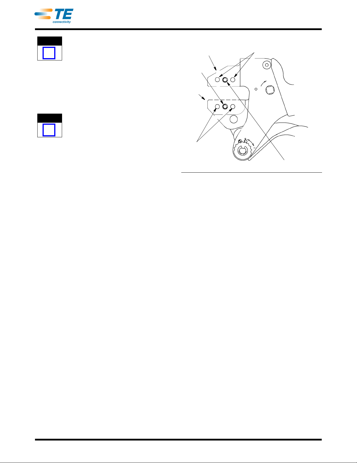
3.2. Installation of Pinned Dies (Figure 3)
1. Install the wire and insulation anvil dies with the
chamfers facing the front of the tool and the die
markings facing outward into the movable jaw of the
frame assembly.
2. Insert the die retaining pins and the short die
retention screw. Do not tighten the screw
completely.
3. Install the wire and insulation crimper dies, with
the chamfers facing the front of the tool, and with
the die markings facing outward into the stationary
jaw of the frame assembly.
4. Insert the die retaining pins and the long die
retention screw. Do not tighten the screw
completely.
5. Slowly close the tool handles allowing the dies to
mate and/or align. Continue closing the tool handles
until the ratchet makes the fifth "click," then tighten
both die retention screws until snug.
3.3. Removal
To remove the die assemblies, close the tool handles
until the tool ratchet releases, and allow the handles to
open fully. Reverse the installation procedure(s).
4. MAINTENANCE/INSPECTION
4.1. Daily Maintenance
TE recommends that operators of the tool be made
aware of, and responsible for, the following steps of
daily maintenance:
1. Remove dust, moisture, and any other
contaminants from the tool with a clean, soft brush,
or a clean, soft, lint-free cloth. Do NOT use hard or
abrasive objects that could damage the tool.
Figure 3
2. Make certain that the pivot pins are in place and
that they are secured with retaining rings.
3. All pins, pivot points, and bearing surfaces should
be protected with a thin coat of any good SAE† 20
motor oil. Do not oil excessively.
4. When the tool is not in use, keep handles closed
to prevent objects from becoming lodged in the
crimping jaws. Store the tool in a clean, dry area.
4.2. Periodic Inspection
Regular inspections of the tool should be performed
by quality control personnel. A record of scheduled
inspections should remain with the tool or be supplied
to supervisory personnel responsible for the tool.
Inspection frequency should be based upon amount of
use, working conditions, operator training and skill,
and established company standards.
1. Remove all lubrication and accumulated film by
immersing the tool (handles partially closed) in a
suitable commercial degreaser that will not affect
paint or plastic material.
2. Make certain that all pivot pins are in place and
secured with retaining rings.
3. Close tool handles until ratchet releases and then
allow them to open freely. If they do not open
quickly and fully, the spring is defective and must be
replaced.
NOTE
i
NOTE
i
Insert Upper Die
Insert
Lower
Die
Short Die
Retention
Screw
Die
Retaining
Pins
Die Retaining Pins
Long Die Retention Screw
† SAE is a trademark.
408-8851
3of 3
Rev C
4. Inspect the tool frame for wear or damage,
paying particular attention to the tool jaws and pivot
points. If damage is evident, refer to Section 6,
TOOL REPLACEMENT. If tool is acceptable,
lubricate and return to service.
This tool is recommended for R&D prototyping,
networking applications, commercial/industrial
maintenance, and field service repair. For other
applications, please contact your Tyco Electronics
Sales Representative or the Tyco Electronics
Tooling Assistance Center at 1-800-722-1111.
5. CRIMP HEIGHT INSPECTION
The crimp height is dependant on the dies. Refer to
the appropriate instruction sheet for die crimp height
inspection.
6. RATCHET (Crimp Height) ADJUSTMENT (Figure 4)
The tool frame assembly features a ratchet
mechanism and adjustment wheel with a range of
settings. The ratchet mechanism ensures that the tool
has completed the cycle. The adjustment wheel
controls the amount of handle pressure exerted on the
tool jaws and crimping dies during the crimping
procedure. Although the ratchet is preset prior to
shipment, it is important that you verify the crimp
height. Also, general use and subsequent wear may
cause the tool to go out of adjustment. It is
recommended that the crimp height be inspected -
and adjusted, if necessary - on a regular basis by
quality control personnel.
This is a general explanation of the procedure. For
specific information, refer to the instruction sheet
packaged with the die assembly.
1. Crimp a contact onto a properly-prepared wire of
the correct size.
Damaged product should not be used. If a
damaged contact is evident, it should be cut from
the end of the wire and replaced with a new one.
Never reuse or re-terminate a terminal.
2. If the crimp height is greater than recommended,
remove the ratchet wheel adjustment screw and
rotate the adjustment wheel counterclockwise (+) to
a higher setting. Repeat as required.
3. If the crimp height is less than recommended,
remove the ratchet wheel adjustment screw and
rotate the adjustment wheel clockwise (-) to a lower
setting. Repeat as required.
4. If the crimp cannot be made to conform to the
dimensions provided in the appropriate product
application specification, the tool and/or dies are
defective and must be replaced.
Figure 4
7. TOOL REPLACEMENT
SDE-SA Hand Crimping Tool Frame Assembly
9-1478240-0 is inspected prior to shipment. It is
recommended that it be inspected upon arrival to
ensure that it has not become damaged during
shipping.
Additional tools may be ordered from:
CUSTOMER SERVICE (038-035)
TYCO ELECTRONICS CORPORATION
PO BOX 3608
HARRISBURG PA 17105-3608
8. REVISION SUMMARY
Since the previous release of this document, the new
company logo has been applied.
NOTE
i
NOTE
i
CAUTION
!
Ratchet Wheel Adjustment Screw
Retaining Plate
Adjustment Wheel

Other manuals for SDE-SA

31

This manual suits for next models

1

Other TE Connectivity Power Tools manuals

TE Connectivity PRO-CRIMPER III User manual

TE Connectivity

TE Connectivity PRO-CRIMPER III User manual

TE Connectivity PRO- CRIMPER III User manual

TE Connectivity

TE Connectivity PRO- CRIMPER III User manual

TE Connectivity 1976330-1 User manual

TE Connectivity

TE Connectivity 1976330-1 User manual

TE Connectivity 59275 User manual

TE Connectivity

TE Connectivity 59275 User manual

TE Connectivity 408-160034 User manual

TE Connectivity

TE Connectivity 408-160034 User manual

TE Connectivity 2390879-1 User manual

TE Connectivity

TE Connectivity 2390879-1 User manual

TE Connectivity 2393336-1 User manual

TE Connectivity

TE Connectivity 2393336-1 User manual

TE Connectivity Micro-MaTch  528405-9 User manual

TE Connectivity

TE Connectivity Micro-MaTch 528405-9 User manual

TE Connectivity SDE-SA User manual

TE Connectivity

TE Connectivity SDE-SA User manual

TE Connectivity 1055258-1 User manual

TE Connectivity

TE Connectivity 1055258-1 User manual

TE Connectivity HT40 User manual

TE Connectivity

TE Connectivity HT40 User manual

TE Connectivity 59981-1 User manual

TE Connectivity

TE Connectivity 59981-1 User manual

TE Connectivity CERTILOK 9-1579022-1 User manual

TE Connectivity

TE Connectivity CERTILOK 9-1579022-1 User manual

TE Connectivity HPi 10 TE Instruction Manual

TE Connectivity

TE Connectivity HPi 10 TE Instruction Manual

TE Connectivity 2063523-1 User manual

TE Connectivity

TE Connectivity 2063523-1 User manual

TE Connectivity 1976330-1 User manual

TE Connectivity

TE Connectivity 1976330-1 User manual

TE Connectivity HT11K User manual

TE Connectivity

TE Connectivity HT11K User manual

TE Connectivity 2390076-1 User manual

TE Connectivity

TE Connectivity 2390076-1 User manual

TE Connectivity SDE-SA User manual

TE Connectivity

TE Connectivity SDE-SA User manual

TE Connectivity 2377026-1 User manual

TE Connectivity

TE Connectivity 2377026-1 User manual

TE Connectivity SDE-SA User manual

TE Connectivity

TE Connectivity SDE-SA User manual

TE Connectivity OCEAN 2.0 User manual

TE Connectivity

TE Connectivity OCEAN 2.0 User manual

TE Connectivity 2430768-1 User manual

TE Connectivity

TE Connectivity 2430768-1 User manual

TE Connectivity 2363592-1 User manual

TE Connectivity

TE Connectivity 2363592-1 User manual

Popular Power Tools manuals by other brands

Grizzly G1778 Instructional manual

Grizzly

Grizzly G1778 Instructional manual

Cooper Hand Tools Weller CSF operating instructions

Cooper Hand Tools

Cooper Hand Tools Weller CSF operating instructions

Facom X.730B instruction manual

Facom

Facom X.730B instruction manual

BGS technic 70056 instruction manual

BGS technic

BGS technic 70056 instruction manual

Fayat Group Bomag BPR 70/70 D Operating instructions, maintenance instructions

Fayat Group

Fayat Group Bomag BPR 70/70 D Operating instructions, maintenance instructions

Matco Tools RL638 Operating instructions, warning information, parts breakdown

Matco Tools

Matco Tools RL638 Operating instructions, warning information, parts breakdown

AEG PM 3 Original instructions

AEG

AEG PM 3 Original instructions

TMG TMG-ABC50 product manual

TMG

TMG TMG-ABC50 product manual

Oliver 4275C owner's manual

Oliver

Oliver 4275C owner's manual

Bosch DL 0 607 453 4 Series Original instructions

Bosch

Bosch DL 0 607 453 4 Series Original instructions

Makita BJS130 instruction manual

Makita

Makita BJS130 instruction manual

Makita DSC251 instruction manual

Makita

Makita DSC251 instruction manual

Chicago Electric 41053 Set up and operating instructions

Chicago Electric

Chicago Electric 41053 Set up and operating instructions

Enerpac W22000 instruction sheet

Enerpac

Enerpac W22000 instruction sheet

Yokota TKA80 manual

Yokota

Yokota TKA80 manual

Craftsman CMEW400 Original instructions

Craftsman

Craftsman CMEW400 Original instructions

Makita HM1800 instruction manual

Makita

Makita HM1800 instruction manual

DeWalt DW252 instruction manual

DeWalt

DeWalt DW252 instruction manual

manuals.online logo
manuals.online logoBrands
  • About & Mission
  • Contact us
  • Privacy Policy
  • Terms and Conditions

Copyright 2025 Manuals.Online. All Rights Reserved.