Teac AG-H500 User manual

ag-h500
`
AM/FM STEREO RECEIVER
9A06774500
This appliance has a serial number located
on the rear panel. Please record the model
number and serial number and retain them
for your records.
Model number
Serial number
WARNING: TO PREVENT FIRE OR SHOCK
HAZARD, DO NOT EXPOSE THIS
APPLIANCE TO RAIN OR MOISTURE.
The exclamation point within an equilateral triangle is intended to alert the user to the
presence of important operating and maintenance (servicing) instructions in the literature
accompanying the appliance.
The lightning flash with arrowhead symbol, within an equilateral triangle, is intended to alert
the user to the presence of uninsulated “dangerous voltage” within the product’s enclosure
that may be of sufficient magnitude to constitute a risk of electric shock to persons.
CAUTION: TO REDUCE THE RISK OF ELECTRIC SHOCK, DO NOT
REMOVE COVER (OR BACK). NO USER-SERVICEABLE PARTS INSIDE.
REFER SERVICING TO QUALIFIED SERVICE PERSONNEL.
Ü
ÿ
Ÿ
Thanks for buying a TEAC. Read this manual carefully to get the
best performance from this unit.
Nous vous remercions pour l’achat d’un appareil TEAC.
Lire ce manuel avec attention pour obtenir les meilleures perfor-
mances possibles de cet appareil.
Vielen Dank für den Kauf dieses TEAC-Geräts.
Bitte lesen Sie diese Anleitung sorgfältig durch, um die Leistungs-
fähigkeit dieses Geräts optimal nutzen zu können.
Grazie per aver acquistato un prodotto TEAC.
Leggere attentamente questo manuale per ottenere le migliori
prestazioni da questo apparecchio.
Enhorabuena por la adquisición de un TEAC.
Lea detenidamente este manual a fin de obtener el mejor
rendimiento de esta unidad.
OWNER’S MANUAL ..................................3
MANUEL DU PROPRIETAIRE................ 16
BEDIENUNGSANLEITUNG..................... 29
MANUALE DI ISTRUZIONI .................... 42
MANUAL DEL USUARIO ....................... 55
ENGLISHFRANÇAISDEUTSCHITALIANOESPAÑOL

Important Safety Instructions
–2 –
CAUTION:
••Read all of these Instructions.
••Save these Instructions for later use.
••Follow all Warnings and Instructions marked on the audio
equipment.
1) Read Instructions — All the safety and operating instructions
should be read before the product is operated.
2) Retain Instructions —The safety and operating instructions
should be retained for future reference.
3) Heed Warnings —All warnings on the product and in the
operating instructions should be adhered to.
4) Follow Instructions —All operating and use instructions should
be followed.
5) Cleaning —Unplug this product from the wall outlet before
cleaning. Do not use liquid cleaners or aerosol cleaners. Use a damp
cloth for cleaning.
6) Attachments —Do not use attachments not recommended by
the product manufacturer as they may cause hazards.
7) Water and Moisture —Do not use this product near water _for
example, near a bath tub, wash bowl, kitchen sink, or laundry tub; in
a wet basement; or near a swimming pool; and the like.
8) Accessories —Do not place this product on an unstable cart,
stand, tripod, bracket, or table.The product may fall, causing serious
injury to a child or adult, and serious damage to the product. Use
only with a cart, stand, tripod, bracket, or table recommended by the
manufacturer, or sold with the product. Any mounting of the product
should follow the manufacturer’s instructions, and should use a
mounting accessory recommended by the manufacturer.
9) A product and cart combination should be moved with care. Quick
stops, excessive force, and uneven surfaces may cause the product
and cart combination to overturn.
"Note to CATV system installer:
This reminder is provided to call the CATV system installer’s
attention to Section 820-40 of the NEC which provides guidelines for
proper grounding and, in particular, specifies that the cable ground
shall be connected to the grounding system of the building, as close
to the point of cable entry as practical."
ANTENNA
LEAD IN
WIRE
ANTENNA
DISCHARGE UNIT
(NEC SECTION 810-20)
GROUNDING CONDUCTORS
(NEC SECTION 810-21)
GROUND CLAMPS
POWER SERVICE GROUNDING
ELECTRODE SYSTEM
(NEC ART 250. PART H)
NEC - NATIONAL ELECTRICAL CODE
ELECTRIC
SERVICE
EQUIPMENT
Example of Antenna Grounding as per
National Electrical Code, ANSI/NFPA 70
GROUND
CLAMP
15) Lightning —For added protection for this product during a
lightning storm, or when it is left unattended and unused for long
periods of time, unplug it from the wall outlet and disconnect the
antenna or cable system. This will prevent damage to the product
due to lightning and power-line surges.
16) Power Lines —An outside antenna system should not be
located in the vicinity of overhead power lines or other electric light
or power circuits, or where it can fall into such power lines or circuits.
When installing an outside antenna system, extreme care should be
taken to keep from touching such power lines or circuits as contact
with them might be fatal.
17) Overloading —Do not overload wall outlets, extension cords, or
integral convenience receptacles as this can result in risk of fire or
electric shock.
18) Object and Liquid Entry —Never push objects of any kind into
this product through openings as they may touch dangerous voltage
points or short-out parts that could result in a fire or electric shock.
Never spill liquid of any kind on the product.
19) Servicing —Do not attempt to service this product yourself as
opening or removing covers may expose you to dangerous voltage
or other hazards. Refer all servicing to qualified service personnel.
20) Damage Requiring Service —Unplug this product from the
wall outlet and refer servicing to qualified service personnel under
the following conditions:
a) when the power-supply cord or plug is damaged.
b) if liquid has been spilled, or objects have fallen into the product.
c) if the product has been exposed to rain or water.
d) if the product does not operate normally by following the
operating instructions. Adjust only those controls that are covered by
the operating instructions as an improper adjustment of other
controls may result in damage and will often require extensive work
by a qualified technician to restore the product to its normal
operation.
e) if the product has been dropped or damaged in any way.
f ) when the product exhibits a distinct change in performance _ this
indicates a need for service.
21) Replacement Parts —When replacement parts are required,
be sure the service technician has used replacement parts specified
by the manufacturer or have the same characteristics as the original
part. Unauthorized substitutions may result in fire, electric shock, or
other hazards.
22) Safety Check —Upon completion of any service or repairs to
this product, ask the service technician to perform safety checks to
determine that the product is in proper operating condition.
23) Wall or Ceiling Mounting —The product should be mounted to
a wall or ceiling only as recommended by the manufacturer.
24) Heat —The product should be situated away from heat sources
such as radiators, heat registers, stoves, or other products (including
amplifiers) that produce heat.
10) Ventilation —Slots and openings in the cabinet are provided for
ventilation and to ensure reliable operation of the product and to
protect it from overheating, and these openings must not be blocked
or covered. The openings should never be blocked by placing the
product on a bed, sofa, rug, or other similar surface. This product
should not be placed in a built-in installation such as a bookcase or
rack unless proper ventilation is provided or the manufacturer’s
instructions have been adhered to.
11) Power Sources —This product should be operated only from
the type of power source indicated on the marking label. If you are
not sure of the type of power supply to your home, consult your
product dealer or local power company. For products intended to
operate from battery power, or other sources, refer to the operating
instructions.
12) Grounding or Polarization —This product may be equipped
with a polarized alternating-current line plug (a plug having one
blade wider than the other).This plug will fit into the power outlet only
one way. This is a safety feature. If you are unable to insert the plug
fully into the outlet, try reversing the plug. If the plug should still fail
to fit, contact your electrician to replace your obsolete outlet. Do not
defeat the safety purpose of the polarized plug.
13) Power-Cord Protection —Power-supply cords should be
routed so that they are not likely to be walked on or pinched by items
placed upon or against them, paying particular attention to cords at
plugs, convenience receptacles, and the point where they exit from
the product.
14) Outdoor Antenna Grounding —If an outside antenna or
cable system is connected to the product, be sure the antenna or
cable system is grounded so as to provide some protection against
voltage surges and built-up static charges. Article 810 of the
National Electrical Code, ANSI/NFPA 70, provides information with
regard to proper grounding of the mast and supporting structure,
grounding of the lead-in wire to an antenna discharge unit, size of
grounding conductors, location of antenna-discharge unit,
connection to grounding electrodes, and requirements for the
grounding electrode.

Before Use
…Place the receiver on a hard, flat
surface.
…The ventilation holes should not be
covered. Make sure there is at least 50
cm (20 inches) of space above and at
least 10 cm (4 inches) of space beside
the receiver. Do not place a CD player or
other equipment on top of the receiver.
…Avoid placing it in direct sunlight or
close to a source of heat. Also avoid
locations subject to vibrations and
excessive dust, heat, cold or moisture.
…Do not open the cabinet, as this might
result in circuitry damage or electrical
shock.
…Do not attempt to clean the unit with
chemical solvents as this might damage
the finish. Use a clean, dry cloth.
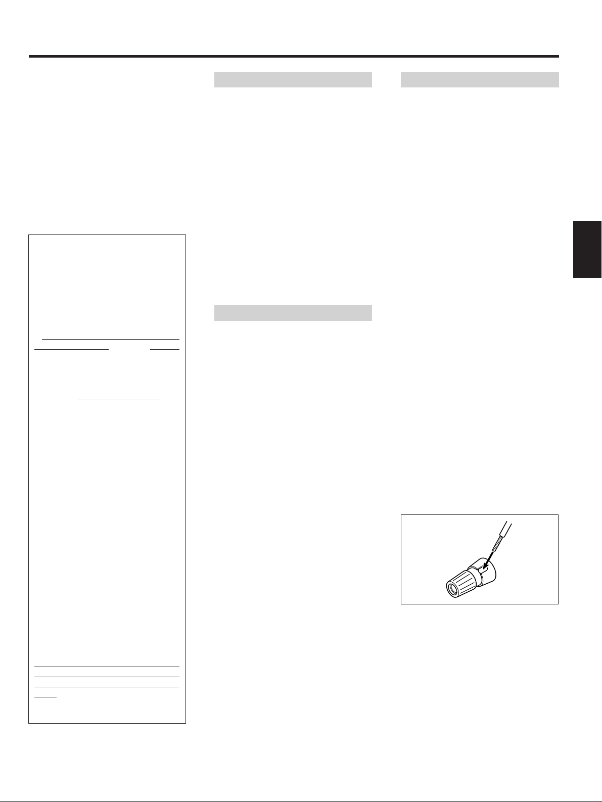
∑How to connect
(1) Twist the wires tightly together so that
they are not straggly.
(2) Turn the terminal cap counterclockwise
to loosen it.
The speaker terminal caps cannot be
fully removed from the base.
(3) Insert the wire into the terminal fully and
turn the terminal cap clockwise to
securely connect it.
(4) Make sure it is fastened firm by pulling
the cord lightly.
Read This Before Operating
Notes on power sources
Caution:
To avoid damaging the speakers by inputing
a sudden high-level signal, be sure to
switch the power off before connecting the
speakers.
∑Before connecting
…Check the impedance of your speakers.
Connect speaker with an impedance of 8
to 16 ohms.
The receiver's red speaker terminals are
the ≠(positive) terminals and the black
terminals are the –(negative) terminals.
…The ≠side of the speaker cable is
marked to make it distinguishable from
the –side of the cable. Connect this
marked side to the red ≠terminal and
the unmarked side to the black terminal.
…Prepare the speaker cords for
connection by stripping off
approximately 10 mm or less (no more as
this could cause a short-circuit) of the
outer insulation.
Speaker Connections
–3 –
ENGLISH
IMPORTANT (for U.K. Customers)
DO NOT cut off the mains plug from this
equipment. If the plug fitted is not
suitable for the power points in your
home or the cable is too short to reach
a power point, then obtain an
appropriate safety approved extension
lead or consult your dealer.
If nonetheless the mains plug is cut off,
remove the fuse and dispose of the plug
immediately, to avoid a possible shock
hazard by inadvertent connection to the
mains supply.
If this product is not provided with a
mains plug, or one has to be fitted, then
follow the instructions given below:
IMPORTANT. DO NOT make any
connection to the larger terminal which
is marked with the letter E or by the
safety earth symbol ç or coloured
GREEN or GREEN-and-YELLOW.
The wires in the mains lead on this
product are coloured in accordance
with the following code:
BLUE: NEUTRAL
BROWN: LIVE
As these colours may not correspond
with the coloured markings identifying
the terminals in your plug proceed as
follows:
The wire which is coloured BLUE must
be connected to the terminal which is
marked with the letter N or coloured
BLACK.
The wire which is coloured BROWN
must be connected to the terminal
which is marked with the letter L or
coloured RED.
When replacing the fuse only a
correctly rated approved type should
be used and be sure to re-fit the fuse
cover.
IF IN DOUBT —CONSULT A
COMPETENT ELECTRICIAN.
Before operating the unit, check that the
operating voltage of the unit is identical to
your local power supply. The operating
voltage is indicated on the nameplate on
the rear panel of the unit.
…Turn off power for all equipment before
making connections.
ªPower cord
…Be sure to connect the power cord to an
AC outlet which supplies the correct
voltage.
…Hold the power plug when plugging or
unplugging the power cord.
ªMain power switch
…The system cannot be turned on when
the main power switch on the side panel
is OFF.
Leave the main power switch ON at all
times.
Table of Contents
Before Use...................................................... 3
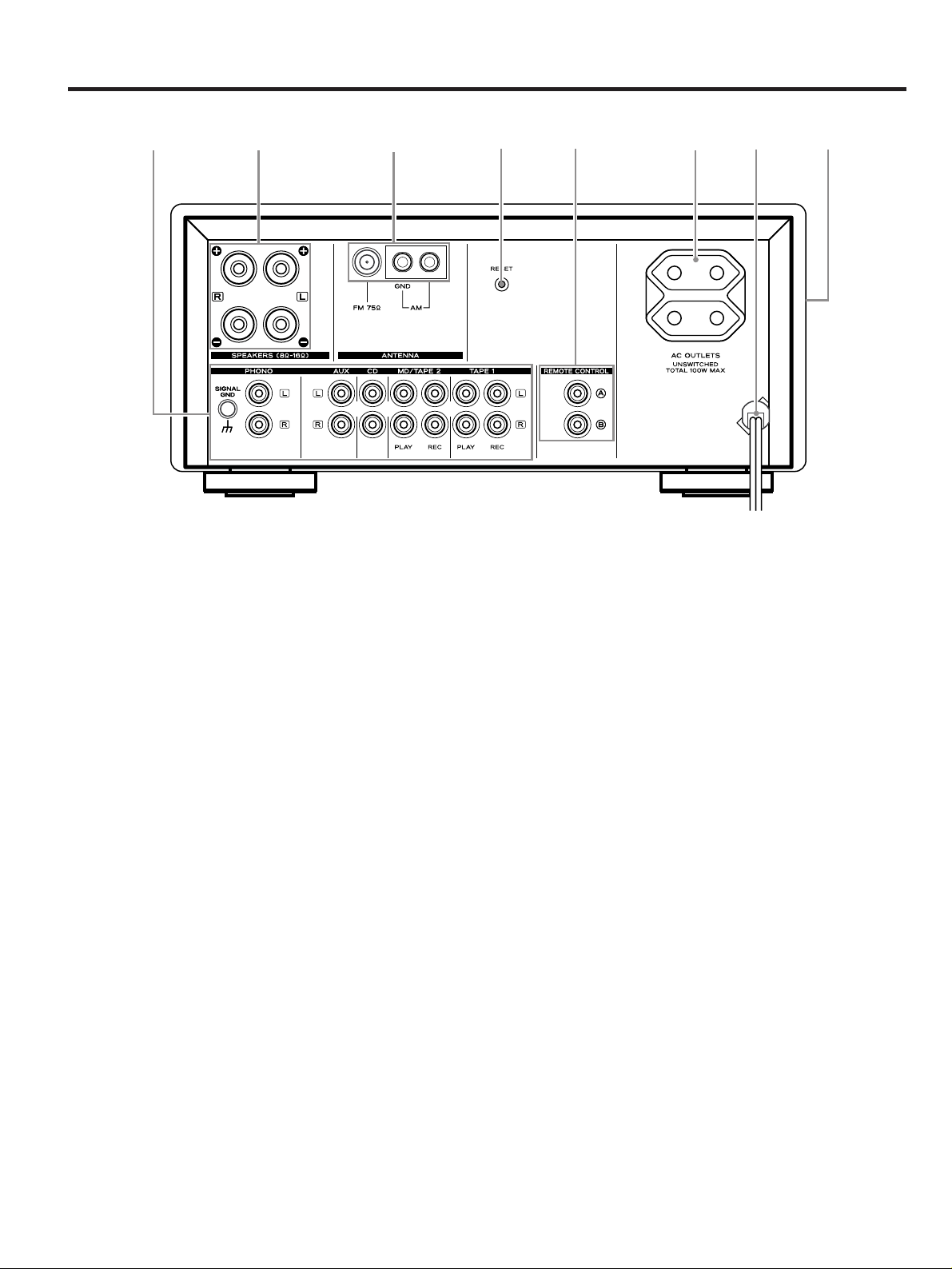
Rear Panel Overview .................................... 4
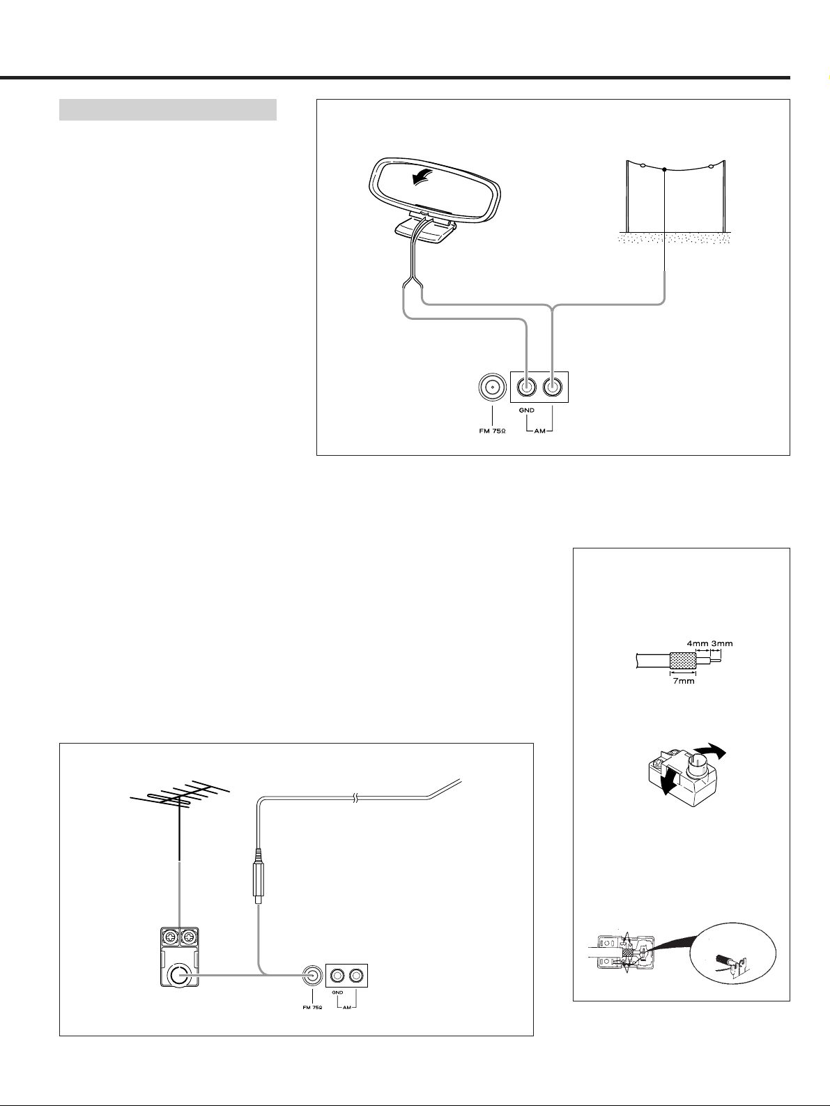
Connections.................................................... 5
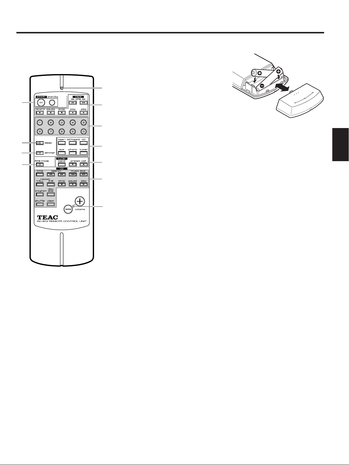
Remote Control Operation............................ 7
Front Panel Controls and
Their Functions......................................... 8
Operating the Amplifier ................................ 9
Operating the Tuner..................................... 10
Specifications............................................... 14
Troubleshooting............................................ 15

Rear Panel Overview
1Audio signal jacks:
Note:
Make sure that you connect the white pin-
plug to the white jacks (left) and the red
pin-plug to the red jacks (right).
…PHONO input jacks
Connect the output jacks of the record
player (turntable) to these jacks.
…AUX input jacks
Connect the output jacks of the VCR or
other AUXiliary source unit to these
jacks.
…CD input jacks
Connect the output (LINE OUT) jacks of
the CD player (PD-H570) to these jacks.
…MD/TAPE 2 (PLAY/REC) jacks
These jacks are used for the connection
of the MD player (MD-H500) or the
second cassette deck.
Connect the output (LINE OUT) jacks of
the MD player or cassette deck to the
PLAY jacks; the input (LINE IN) jacks of
the MD player or cassette deck to the
REC jacks.
…TAPE 1 (PLAY/REC) jacks
Connect the output (LINE OUT) jacks of
the cassette deck (R-H500) to the PLAY
jacks; the input (LINE IN) jacks of the
cassette deck to the REC jacks.
2Speaker terminals (see page 3.)
3Antenna terminals
4RESET switch
Press the RESET switch once or twice with
a pencil or a ball-point pen lightly.
…If you press this RESET switch, all the
memories will be erased. In this case, try
to preset stations again.
5REMOTE CONTROL jacks
These jacks are used for the connection of
the TEAC Mini component system (PD-
H570, PD-H500, R-H500) for the purpose of
operating it using the Remote Control unit
(RC-613 provided with the receiver) or
system control signals.
6AC OUTLETS (unswitched)
Plug the AC power cord of the source unit
(CD player, cassette deck, etc.) into this AC
OUTLETS.
7AC power cord
Plug the AC power cord into an AC wall
socket.
8Main power switch
Press the ON side of this rocker (seesaw)
switch to turn the power ON (standby
position); press the OFF side to turn the
power off.
Note:
Leave the main power switch ON at all
times.
–4 –
78645321

Connections
…Turn off power for all equipment before
making connections.
…Read instructions of each component
you intend to use with the receiver.
System Connections
–5 –
ENGLISH
Speaker placement
The playback characteristics of the
speakers are greatly influenced by the
placement and the room in which the
speakers are used. To find the best location
for the speakers play back some music
without using the tone controls and move
the speakers around. However, please keep
the following in mind:
…Place the speakers on a flat, solid
surface which is free from vibrations.
…Place the speakers in an area that is well
ventilated. Do not place the speakers in
a humid place.
…Keep the speakers away from direct
sunlight and heat sources (stoves, etc.).
…Keep the speakers away from the
turntable.
VCR or auxiliary source unit
LL
RR
White White
White
Red
Red Red
Audio connection cords
MD DECK
Turntable
Right
Speaker
Left
Speaker
AC Outlets:
Two unswitched, Total 100W.
Refer to "Antenna Installation" on page 6 .
CASSETTE DECK (R-H500)
CD PLAYER
(PD-H500/PD-H570)
To AC outlet
LINE OUT
LINE OUT
AUDIO OUT
LINE IN
LINE OUT
Remote control cord
Remote control cord
LINE IN
Remote
control cord

Connections
Antenna Installation
–6 –
∑Installation of FM antenna
FM indoor antenna
If you live reasonably close to a transmitter
and want to use the provided lead-type FM
antenna, you will have to connect it direct
to the "FM 75Ω" socket. Fit the metal sleeve
of the lead-type antenna over the core
(center) conductor of the "FM 75Ω" socket,
extend the lead and fix it to a window frame
or wall with thumbtacks, or the like, where
reception is best.
∑Installation of AM antenna
AM indoor antenna
Connect an AM antenna to the AM antenna
terminal on the rear panel.
Without an AM antenna, you cannot
receive AM broadcasting.
Outdoor antenna
When you install an AM outdoor antenna, it
is recommended that you should avoid
high-voltage cables, materials of metal,
roadside and so on (mountains or places
near a building) near the antenna.
It is better to install an antenna far away
from high-voltage cables, valleys, or
buildings.
How to assemble AM antenna
…Install it after assembling an antenna as
shown.
FM outdoor antenna
Generally, a 3-element antenna will be
sufficient; if you live in an area where the
FM signals are particularly weak, it may be
necessary to use one with 5 or more
elements. Connect the coaxial cable of the
antenna to the matching transformer as
shown. After completing connection, plug
the transformer into the "FM 75Ω" socket.
Caution
It is recommended that an outdoor antenna
should be installed by an antenna expert.
How to connect a coaxial cable to
the matching transformer
1Strip the cable and dress it as
shown.
2Press both side tabs outward to
remove the cover.
3Wrap the core conductor around
the central metal fixture as shown.
Crimp the jagged metal fixtures so
they hold the braided portion using
pliers, etc. Put the cover back in
place.
Outdoor FM antenna (75Ω)FM indoor antenna
AM loop antenna AM outdoor antenna
Jagged metal
Jagged metal
Insert into slit.
Matching Transformer
(Optional)
Lead-type FM antenna (75Ω)(provided)

Remote Control Operation
–7 –
ENGLISH
When operating the remote control unit,
point it towards the remote sensor on the
front panel of the unit.
1power standby buttons
on:Press to turn the system on.
standby:Press to set the system to standby
mode.
2Indicator
This indicator will blink when a remote
control signal is transmitted by pressing a
button.
Note:
The indicator has two colors:
One is green in the CD mode; the other is
red in other mode.
3tape deck operation buttons
4Numeric buttons
These buttons are used for selecting the
preset channel in tuner mode, or the track
number in CD mode.
…Using the input selector buttons, select
CD or tuner before operating the
numeric buttons.
When entering a single-digit number, enter
0 for the 10's digit followed by the desired
1's digit.
When entering a double-digit number, first
enter the 10's digit then the 1's digit.
For example:
To enter 15:
(1) Press "1", and "1" starts blinking.
(2) While it is blinking, press "5".
5Input selector buttons
6tuner operation buttons
band:
Selects between FM and AM broadcasts.
preset call:
Allows you to tune to preset channels in
sequence.
7CD player operation buttons
8volume buttons
+: Press to increase the volume.
–: Press to decrease the volume.
9sleep button
This button is used for engaging the sleep
timer in the tuner.
0dimmer button
Press this button when you want to darken
the FL displays on the tuner, CD player and
cassette deck.
Press it again to resume the original
brightness.
qRDS (Radio Data System) mode
button (See pages 12 & 13.)
ªBattery Installation
1. Remove the battery compartment
cover.
2. Insert two “AAA” (R03, UM-4) dry
batteries.
Make sure that the batteries are
inserted with their positive ±and
negative —poles positioned correctly.
3. Close the cover until it clicks.
Battery Replacement.
If you notice that the distance between
the remote control unit and the player for
correct operation becomes shorter, it
indicates that the batteries are exhaus-
ted. In this case replace the batteries with
new ones.
Precautions concerning batteries
…Be sure to insert the batteries with
correct positive ±and negative —
polarities.
…Use batteries of the same type. Never
use different types of batteries
together.
…Rechargeable and non-rechargeable
batteries can be used. Refer to the
precautions on their labels.
…When the remote control unit is not to
be used for a long time (more than a
month), remove the batteries from the
remote control unit to prevent them
from leaking. If they leak, wipe away
the liquid inside the battery
compartment and replace the batteries
with new ones.
…Do not heat or disassemble batteries
and never dispose of old batteries by
throwing them in a fire.
1
9
0
q
2
3
4
5
6
7
8

Front Panel Controls and Their Functions
1power standby/on button &
indicator
When the main power switch on the side
panel is ON:
Press this button to turn the power on, and
the whole system connected by remote
control connection cables is turned on.
Press it again to turn the system off (power
standby mode).
Notes:
…This indicator lights up in power standby
mode and goes out when this unit is
turned on.
…The system cannot be turned on when
the main power switch on the side panel
is OFF.
2input selector & indicators
Rotate this selector to select the desired
input (tape 1, MD/tape 2, CD, tuner, phono,
aux) source.
3phones jack
Connect the headphone plug to this jack,
and sound to the speakers will be cut off.
Note:
Decrease the volume level to minimum
(∞position) before connecting head-
phones.
4remote sensor
This sensor receives the signal from the
remote control transmitter.
5Tone (bass/treble) controls
These two tone controls –bass and treble –
can be used to obtain a "flat" frequency
response or a tone which suits your
individual listening preference. The bass
control adjusts low frequencies and the
treble control adjusts the high frequencies.
6Display window
7balance control
This control is used for adjusting the
balance of the volume level between the
left and right channels.
8FM mode button
This unit automatically switches into the
stereo mode when a stereo broadcast is
received.
Press this button to listen to the radio in the
monaural mode, then the STEREO indicator
on the display will go out.
9memory button
This button is used for presetting the
broadcast stations. (See page 11.)
0band button
This button is used for selecting the FM or
AM broadcasting.
qtuning/preset up ( ) or down
( ) button
This button is used for tuning in the desired
broadcasting stations, or adjusting the
tuned frequency.
wtuning mode button
Each time you press this button, tuning
mode will change as follows:
Manual tuning TPreset tuning
After selecting the desired tuning mode by
pressing this button, tune in the desired
broadcast by pressing the tuning/preset up
( ) or down ( ) button.
emaster volume control
This control is used for adjusting the signal
output level to the speakers.
–8 –
e54317q980 w62

Operating the Amplifier
–9 –
ENGLISH
1Set the volume control to the ∞position
before beginning.
2power
Turn the system on by pressing the
power button.
3Select the source you want to listen to
by rotating the input selector knob.
4Operate the source unit to be played.
(Refer to the operating instructions of
each unit.)
5Adjust the volume level.
1. When you turn on the system, the source
unit that has been selected by the input
selector will start playing automatically.
This AI direct play function allows you to
restart operation using the source unit
(tape deck, CD player or tuner) when
power was last turned off.
For example:
(1) When the system is switched off with
the input selector set to the CD position
and a disc loaded in the CD player, T(2)
the next time you switch the power on,
T(3) the CD player will start playing
automatically from the first track on the
disc.
2. When you select the desired source by
rotating the input selector, the selected
source unit will start playing
automatically.
For example:
(1) While you are listening to a CD, T(2)
if you select tape 1, T(3) tape 1 will start
playing and the CD player will pause
automatically.
3. When you play a source unit by pressing
the play button, that source will be
selected automatically by the input
selector.
For example:
(1) While you are listening to a CD, T(2)
if you press the play button (”or ∏) on
the cassette deck (tape 1, R-H500), T(3)
the input source will be changed to tape
1 automatically.
1Select a source to be recorded using
the input selector.
2Play the source.
3Set the MD deck or the tape deck to
recording mode.
1Set the input selector to MD/tape 2.
2Play deck 1 (or deck 2).
3Set deck 2 (or deck 1) to recording
mode.
Notes:
…When dubbing is attempted using two
R-H500s (or MD decks), be sure not to
connect the remote cable to deck 2. If it
is connected, dubbing is not possible.
…When a second deck such as another
R-H500 (or MD deck) is connected to
MD/TAPE 2 terminals, dubbing from deck
1 to deck 2 is possible. However, remote-
controlled operation of deck 2 is not
possible. Therefore, do not connect the
remote cable from deck 1 to deck 2.
…When dubbing from deck 1 to deck 2 (or
an MD recorder), set the input selector
to MD/tape 2, then start deck 2 (or the
MD recorder) for recording and press
the play button on deck 1.
Basic Operation AI Direct Play Function
Dubbing (Recording from deck 1
to deck 2 or vice versa)
Recording
23 15
1
Deck 1
AG-H500
Deck 2 (Do not connect
the remote cable.)

Operating the Tuner
This function allows you to preprogram the
receiver to switch its own power off
automatically.
You can then enjoy the audio system for a
specified amount of time without having to
worry about turning the unit off later.
Press the sleep button on the remote
control unit.
Each press of the sleep button changes the
time indication by 10 minutes.
∑sleep–90∑sleep–80∑... ∑sleep–10
(released condition) ß
To let the remaining time (until power off)
appear on the display while the sleep timer
is engaged, press the sleep button once. 1Select the tuner function.
2Select the AM or FM by pressing the
band selector button.
3Press the tuning mode button to change
to tuning mode.
(The PRESET CH. indicator disappears
from the display).
…This button is used to select tuning or
preset scan mode.
4Press the tuning/preset up ()or
down ()button (within 0.5 to 2
seconds).
The next station broadcasting at a
frequency higher or lower than that of
the current station is automatically
detected and tuned in.
…By pressing and holding the tuning/
preset up ( ) or down ( ) button for
longer than 2 seconds, it will continue to
control (three times faster than normal
speed).
Manual Tuning is generally used to tune to
stations broadcasting a signal that is too
weak to be received by Auto Tuning.
1Select the tuner function.
2Select the AM or FM by pressing the
band selector button.
3Press the tuning mode button to change
to tuning mode.
(The PRESET CH. indicator disappears
from the display).
4When the tuning /preset up ()or
down ()button is pressed
momentarily (0.5 second or less), the
frequency changes by a fixed step (see
STEPS below).
STEPS
Models for General Export/Europe
FM: 50-kHz steps
AM: 9-kHz steps
Manual Tuning
Radio ReceptionSleep Timer Operation
Auto Tuning
–10 –
1243
1243

This facility is used to store FM, AM
broadcasting from Channel 1 to 30
respectively.
1Press the tuner function.
2Select the AM or FM by pressing the
band selector button.
3Press the tuning mode button to change
to tuning mode.
(The PRESET CH. indicator disappears
from the display).
4Select the frequency you want to preset
by pressing the tuning/preset up ()
or down ()button.
5Press the memory button briefly,
MEMORY display will blink at an
interval of 1 second.
6While the MEMORY indicator is lit,
press the tuning/preset up ()or
down ()button to input the channel
number in which the data (AM or FM
band and frequency) for the broadcast
is to be stored.
7Press the memory button again.
∑Recalling Frequencies
Press the numeric buttons on the remote
control corresponding to the channel
number to tune directly to a broadcast.
∑FM mode Butoon
Pressing this button alternates between
Stereo mode and Mono mode.
…Stereo
FM stereo broadcasts are received in
stereo and the STEREO indicator lights in
the display.
Monophonic broadcasts are received in
mono. If FM broadcasts with weak signal
strength are received, the FM muting
(–20 dB) function works automatically to
cut the signals, eliminating loud noise.
…Mono
To compensate for weak FM stereo
reception, select this mode. Reception
will now be forced monaural, reducing
unwanted noise.
…TUNED Indicator
''TUNED'' appears in the display when a
broadcast is correctly tuned in.
∑"Back-up" memory function
This function conserves the already preset
station memories, and "Most-recent"
memory function, even in the event of a cut-
off of power supply, as when the plug is
pulled out of the wall outlet, for 3 days.
Preset Tuning
–11 –
ENGLISH
Automatic Memory Presetting
Manual Memory Presetting
1Select the tuner function.
2Select the AM or FM by pressing the
band selector button.
3Press the memory button for a while (for
more than 1.5 seconds).
¡The start frequency will show in the
display.
…87.5 MHz in FM, 522 kHz in AM.
™The frequency and display will
automatically scan.
…50 kHz steps for FM, 9 kHz steps for
AM.
£The frequency shown in the display
will rapidly change. As each station
is located a preset number will
appear in the display indicating
which preset memory button has
been assigned to the station located.
The scanning process will continue
to operate in this fashion until 30
stations have been found and
entered into the preset memory or
when there are no more stations to
be found on the waveband chosen.
The memory indicator will extinguish
and let you hear the last station to be
memorized.
…To listen to the memorized station select
the band required and press the
numeric keys button 1, 2, 3 etc.
4The last memorized channel of each
band will be displayed when Auto
Memory is completed. Check the
programmed frequencies with the
tuning/preset up ()or down ()
button.
12
34
12
57 43
6

Operating the Tuner
RDS is a broadcasting service which allows
stations to send additional information
along with the regular radio program signal
RDS services can be received only in FM
band.
(1) PS mode:
…When you select PS with the RDS mode
button, "PS" will blink for about 4
seconds.
…After 4 seconds, PS or a station name
entered by manual file will be displayed.
(2) CT mode:
…When you select CT with the RDS mode
button, "CT" will blink for about 4
seconds.
…After 4 seconds, the clock time together
with the frequency will be displayed.
(3) PTY mode:
…When you select PTY with the RDS
mode button, "PTY" will blink for about 4
seconds.
…After 4 seconds, the type of received
PTY will be displayed.
There are 31 kinds of PTY data as follows:
NEWS brief annoucements, events,
public opinion, reports, actual
situations.
AFFAIRS a kind of suggestion including
practical annoucements
other than news, documents,
discussion, analysis and so
on.
INFO daily information or reference
such as weather forecast,
consumer guide, medical
assistance and so on.
RDS function is operational only with
Remote Control.
SPORT sports-related programs.
EDUCATE educational and cultural
information.
DRAMA all kinds of radio concert and
serial drama.
CULTURE all aspects of national or local
culture including religious
events, philosophy, social
science, language, theatre,
and so on.
SCIENCE programs on natural science
and technology.
VARIED popular programs such as quiz,
entertainment, private
interview, comedy, satire and
so on.
POP M program on commercial,
practical and popular songs,
and sale volume of discs, etc.
ROCK M practical modern music
generally composed and
played by young musicians.
M.O.R.M popular music usually lasting
for less than 5 minutes.
LIGHT M classical music, instrumental
music, chorus, and light
music favoured by non-
professionals.
CLASSICS orchestra including great
operas, symphony, chamber
music and so on.
OTHER M other music styles (Rhythm &
Blues, Reggae, etc.)
WEATHER weather reports, forecast
FINANCE financial reports, commerce,
trading
CHILDREN children’s programs
SOCIAL-A social affairs
RELIGION religious programs
PHONE-IN program in which the public
expresses its view by phone
TRAVEL travel reports
HOBBIES programs concerning
recreational activities
JAZZ jazz music
RDS (Radio Data System)
RDS Display
–12 –
1Select the tuner function.
2Press the band button to select FM.
RDS can be received only in FM.
3Select the RDS broadcasting by use of
the tuning mode button and the
tuning/preset up ()or down ()
button.
Then RDS will light up in the upper side
of the display. And the related data, if
received, will be displayed in the type of
received data (PTY, RT, TP, TA).
…PS (Program Service Name): displays
FM station name.
…CT (Clock Time): displays the information
about times provided from the station.
…PTY (Program Type): program type will
be displayed while receiving FM.
…RT (Radio Text): displays the news of
stations composed of up to 64 symbols.
…TP (Traffic Program)
…TA (Traffic Announcement)
4Press the RDS mode button.
…The default of the RDS mode is PS.
Each time you press the button briefly
(0.5 sec or less), the modes will change
as follows regardless of the current
mode.
TPSTCTTPTYTRTTTATRDS off
1233
21
3
4

COUNTRY country music
NATION-M national music
OLDIES music from the so-called
golden of popular music
FOLK-M folk music
DOCUMENT documentaries
TEST
ALARM this is a program notifying an
emergency or a natural
disaster.
(4) RT mode:
…When you select RT with the RDS mode
button, "RT" will blink for about 4
seconds.
…After 4 seconds, the data of received RT
will be displayed.
…If there is no RT data among received
broadcastings, RDS mode will be
automatically switched to PS mode.
(5) TA mode (TP Search Function):
…When you select TA with the RDS mode
button, "TA" will blink for about 4
seconds.
…After 4 seconds, TP received broad-
casting will be searched with FM
frequency increasing in 50 kHz steps.
…If TP received broadcasting is searched,
the increase in frequency will stop and it
is asked whether TA will be received or
not.
…When TA is received, the input selector
of the amplifier/receiver will be auto-
matically switched to the tuner.
…When TA has finished, the input selector
of the amplifier/receiver will auto-
matically return to the previous position.
…If TP and TA turn off while you are
receiving TA, the tuner will search TA
broadcasting again with FM frequency
increasing in 50 kHz steps.
1Select the tuner function.
2Press the band button to select FM.
3Press the RDS mode button on the
remote control for longer than 1.5
seconds.
Then "PTY SEEK" will be shown in the
display.
4Select the desired PTY mode by using
the tuning/preset (or the preset call) up
()or down ()button.
…Select your desired one from among 31
kinds of PTY programs. (The program
will blink.)
5Press the band button.
The program indicator is changed to
light steadily.
6Press the tuning/preset (or the preset
call) up ()or down ()button.
(Searching will start.)
…When the PTY mode that you have
selected is searched, searching will
stop and the PTY mode will be displayed.
…When you press the tuning/preset (or
the preset call) up ( ) or down ( )
button after your desired program is
searched, you can continue to search
for the same program type by increasing
or decreasing the frequency from the
current one.
…If the same program type is not found
during PTY search, it will stop at the
beginning frequency.
…If you want to cancel PTY search while
searching, press the RDS mode button.
Searching will stop and search mode
will be released automatically.
BACK-UP memory
This is the function which preserves the
preset memory and most-recent memory
functions. In the event of a power failure, or
if the power cord of this unit is
disconnected from the electric outlet, the
back-up memory will preserve the preset
memory and most-recent memory
functions for as long as approximately 3
days.
To Prevent Erasing the Memory
If the power supply is interrupted for 3 days
or longer, the memory settings will be
erased.
–13 –
ENGLISH
Back-up memory function
1. When this system is subjected to an
electrical shock.
2. When the power is irregular.
In these cases, try the following (in
power standby mode):
WHEN TO USE RESET SWITCH
How to Search For Your Desired
Program Using PTY Search
Note: When the RESET switch is pressed,
all the memory will be canceled.
Press the RESET switch lightly once
or twice with a pencil or a ballpoint
pen.
RESET SWITCH
–Rear panel –

Specifications
Amplifier Section
Power Output :
40W + 40W (8Ω, 1kHz, 0.1%)
Total Harmonic Distortion :
0.05% (1kHz, 8Ω, 40W)
S/N :
Phono : 65dB
Aux, CD, Tape, Tuner : 90dB(IHF-A)
Input Sensitivity/Impedance :
Phono : 2.5mV
Aux, CD, Tape, Tuner : 200mV/47kΩ
Frequency Response :
5Hz–75kHz (1kHz, ±3dB point)
Tone Control :
Bass : ±10dB (100Hz)
Treble : ±10dB (10kHz)
Channel Separation : 60dB
FM Tuner Section
(Without notes 100.1MHz, 65dB)
Tuning Range :
87.50MHz to 108.00MHz
(50kHz steps)(Europe)
Usable Sensitivity (IHF) :
Mono : 15dBf
Total Harmonic Distortion (1kHz) :
Mono : 0.4%
Stereo : 0.5%
Quieting Sensitivity :
Mono : 30 dBf
Image Rejection Ratio : 40dB
AM Suppression Ratio : 40dB
Frequency Response :
30Hz–15kHz (+1/–1.5dB)
Stereo Separation (1kHz) : 30dB
S/N Ratio :
Mono : 65dB
Stereo : 60dB
AM Tuner Section
Tuning Range :
522kHz to 1620kHz
(9kHs steps)
Usable Sensitivity (IHF) : 55dB/m
Total Harmonic Distortion (1kHz) : 1.5%
S/N Ratio : 35dB
General
Power Requirement : AC 230V, 50Hz
Power Consumption : 100W
Dimensions (W x H x D) : 285 x 131 x 352mm
Weight (net) : 6kg
Standard Accessories :
AM Loop Antenna x 1
Lead-type FM Antenna x 1
Remote Control Unit (RC-613) x 1
…Improvements may result in
specification of feature changes without
notice.
…Illustrations may differ slightly form
production models.
–14 –

Troubleshooting
–15 –
ENGLISH
Problem Probable Cause Remedy
Amplifier
When listening to the music in stereo, Speakers are connected wrongly. After checking, if needed, connect correctly
left/right speaker sounds reversed. again.
Low hum or buzzer sound. Power line of fluorescent light is install- Place this product from electric devices
ed near to wall outlet of this product. as far away as possible.
Sound is only heard from one channel. One of the input cords is disconnected. Connect the input cords securely.
The balance control is set to one end. Adjust the balance control.
Sound cut during listening to the music Speaker impedance is less than After turning off the power and then turning
or no sound even though power is ON. prescribed for this unit. it on again, reduce the volume or change to
the regulated speakers.
Tuner
An unusual hissing noise is heard when A slight noise may be heard because …Try reducing the treble sound by turning
listening to the broadcast in stereo, the method use for modulation of FM the treble controls.
but not heard when listening stereo broadcasts is different from that …Try changing the location, height and/or
monaurally. used for monaural broadcasts. direction of the antenna.
…Set the FM mode to monaural by pressing
Noise is excessive in both stereo and Poor location and/or direction of the the FM mode button. (Note that the
monaural broadcasts. antenna. broadcast will then be heard as monaural
sound.)
Transmitting station is too far away. …If an indoor antenna is being used, change
to an outdoor antenna.
Sound is distorted and/or the volume Broadcast signals are being disturbed. …Try using an antenna with more elements.
level becomes low.
Excessive distortion in the sound of Speaker system connections are not
stereo broadcasts. correct.
Remote Control Unit
Remote control impossible. The batteries are exhausted. Replace with new batteries.
The remote control unit is too far from Operate the remote control unit within the
the receiver or out of the effective range. effective range.
To determine any problem with your receiver, always check the most obvious possible causes first. If any problem still remains after you
have checked the items below, consult your nearest TEAC dealer.

Avant utilisation
– 16 –
Table des matières
Avant utilisation ........................................... 16
Description du panneau arrière................ 17
Raccordements............................................ 18
Fonctionnement àl'aide
de la télécommande.............................. 20
Commandes et fonctions du
panneau avant........................................ 21
Fonctionnement de l'amplificateur........... 22
Fonctionnement du syntoniseur................ 23
Caractéristiques techniques...................... 27
En cas de difficultes.................................... 28
Bien lire ceci avant utilisation
…Placer le récepteur sur une surface
plate rigide.
…Les trous de ventilation ne doivent pas
être couverts. S'assurer qu'il y a un
espace d'au moins 50 cm au dessus et
d'au moins 10 cm àcôtédu récepteur.
Ne pas placer un lecteur CD ou un autre
appareil sur le dessus du récepteur.
…Eviter de le placer directement au soleil
ou près d'une source de chaleur. Eviter
également les endroits sujets aux
vibrations, et àla poussière, la chaleur,
le froid ou l'humidité.
…Ne pas ouvrir le coffret, il pourrait en
résulter un dommage de l'électronique
ou des chocs électriques.
…Ne pas essayer de nettoyer l'appareil
avec des solvants chimiques, ils
pourraient endommager le fini. Utiliser
un chiffon sec et propre.
Attention:
Pour éviter d'endommager les haut-
parleurs en entrant soudainement un signal
de niveau élevé, bien couper l'alimentation
avant de raccorder les haut-parleurs.
∑Avant d’effectuer les raccordements
…Vérifiez l’impédance des enceintes.
Vous pouvez brancher des enceintes
ayant une impédance de 8 à16 ohms.
Sur le récepteur les bornes rouges
SPEAKER sont les bornes ≠(positives),
les noires sont les bornes –(négatives).
…L’extrémité≠du câble de l’enceinte est
marquée pour la distinguer de
l’extrémité–. Branchez l’extrémité
marquée sur la borne rouge ≠, et
l’extrémiténon marquée sur la borne
noire.
…Avant de brancher les cordons des
enceintes, préparez-les en dénudant le
fil sur 10 mm maximum. (le dénuder
davantage peut provoquer un court-
circuit.)
∑Branchement des enceintes
(1) Torsadez les fils ensemble pour éviter
qu’ils ne partent dans tous les sens.
(2) Dévisser le bornier en tournant dans le
sens inverse des aiguilles d’une montre.
Il n’est pas possible de le retirer
complètement.
(3) Insérer le fil àfond dans la borne.
Resserrez le bornier en le tournant dans
le sens des aiguilles d’une montre pour
bien bloquer le fil.
(4) Assurez-vous que le fil est bien fixéen
place en tirant légèrement sur le
cordon.
Branchement des haut-parleurs
Remarques sur les sources
d'alimentation
Avant de faire fonctionner l’appareil,
vérifier que la tension de fonctionnement
de l’appareil est identique àcelle de votre
alimentation secteur locale. La tension de
fonctionnement est indiquée sur la plaque
signalétique sur le panneau arrière de
l’appareil.
…Couper l'alimentation de tous les
appareils avant de faire des
raccordements.
ªCordon d'alimentation
…Bien brancher le cordon d'alimentation
sur une prise de courant qui fournit la
tension correcte.
…Tenir la fiche d'alimentation en
branchant ou débranchant le cordon
d'alimentation.
ªInterrupteur principal
…La chaîne ne peut pas être mise en
marche si l'interrupteur principal sur le
panneau latéral est sur OFF.
Laissez en permanence l'interrupteur
principal sur ON.

–17 –
FRANÇAIS
Description du panneau arrière
1Prises des signaux audio:
ATTENTION:
Veillez àbien raccorder la fiche blanche
aux connecteurs blancs (connecteurs
gauches, marqués L); la fiche rouge aux
connecteurs rouges (connecteurs droite,
marqués R).
…Connecteurs d’entrée PHONO
Branchez les connecteurs de sortie de la
platine disque sur ces connecteurs.
…Connecteurs d’entrée des sources
annexes (AUX)
Branchez les connecteurs de sortie du
magnétoscope ou des autres sources
annexes.
…Connecteurs d’entrée CD
Branchez les connecteurs de sortie
(LINE OUT) du Lecteur de CD (PD-H570)
sur ces connecteurs.
…Connecteurs PLAY/REC
(lecture/enregistrement) / MD/TAPE
2 (MD/PLATINE CASSETTE 2)
Ces connecteurs permettent de
raccorder le Lecteur de MD (MD-H500)
ou une seconde platine cassettes.
Reliez les connecteurs de sortie (LINE
OUT) du Lecteur de MD ou de la platine
cassette aux connecteurs de lecture
(PLAY); les connecteurs d'entrée (LINE
IN) du Lecteur de MD ou de la platine à
cassette aux connecteurs
d’enregistrement (REC).
…Connecteurs PLAY/REC (lecture/
enregistrement) / TAPE 1 (PLATINE
CASSETTE 1)
Reliez les connecteurs de sortie (LINE
OUT) de la platine àcassette (R-H500)
aux connecteurs de lecture (PLAY); les
connecteurs d’entrée (LINE IN) de la
platine cassette aux connecteurs
d’enregistrement (REC).
2Bornes de haut-parleur
(voir page 16.)
3Bornes d'antenne
4Bouton RESET (remise àzéro)
Appuyez une ou deux fois sur le bouton
RESET àl'aide d'un crayon ou d'un stylo à
bille
…Lorsque vous appuyez sur le bouton
RESET, toutes les mémoires sont
effacées.
Il conviendra alors de prérégler de
nouveau les stations.
5Prises REMOTE CONTROL
(Télécommande)
Ces prises permettent de brancher les
divers éléments de la mini- chaîne TEAC
(PD-H570, PD-H500, R-H500), de façon à
pouvoir les commander àl’aide de la
télécommande (RC-613 fournie avec le
récepteur) ou des signaux de commande
de la chaîne.
6Connecteurs UNSWITCHED /
«AC OUTLETS »
Branchez le cordon d’alimentation des
différents appareils (lecteur de CD,
magnétophone, etc.) sur ces connecteurs
AC OUTLETS.
7Cordon d’alimentation CA
Branchez le cordon d’alimentation sur une
prise murale CA.
8Interrupteur POWER
(Marche/arrêt)
Positionnez cet interrupteur sur ON
(Marche) pour mettre l’appareil sous
tension (position veille); positionnez le sur
OFF pour éteindre l’appareil.
REMARQUE:
Laissez en permanence l’interrupteur
principal sur ON.
78645321

–18 –
Raccordements
…Couper l'alimentation de tous les
appareils avant de faire des
raccordements.
…Lire les instructions de chaque appareil
que vous avez l'intention d'utiliser avec
le récepteur.
Raccordements de système Positionnement des enceintes
Les caractéristiques de reproduction
sonore des enceintes sont fortement
influencées par la position des enceintes et
la pièce dans laquelle elles sont placées.
Pour définir le meilleur emplacement pour
les enceintes, écouter un certain nombre
de titres sans utiliser les commandes de
réglage de la tonalitéet faites des essais en
plaçant les enceintes àdifférents endroits.
Veillez toutefois àtoujours respecter les
consignes suivantes:
…Placez les enceintes sur une surface
plane stable et non exposée aux
vibrations.
…Placez les enceintes dans un endroit
bien ventiléet àl’abri de l’humidité.
…Evitez d’exposer les enceintes àla
lumière directe du soleil ou àproximité
d’une source de chaleur (appareil de
chauffage, etc.).
…Placez les enceintes àune bonne
distance du tourne-disques.
Magnétoscope ou autre source annexe
LL
RR
Blanc Blanc
Blanc
Rouge
Rouge Rouge
Cordons de raccordement audio
PLATINE MD
Tourne-disques
Droite
Enceinte
Gauche
Enceinte
Prises secteur CA: Deux non commutées,
total 100W max. ou 1A
Se reporter à ''Installation de l'antenne'' aux page 19.
MAGNETOPHONE A
CASSETTE (R-H500)
LECTEUR DE CD
(PD-H500/PD-H570)
Vers prise
secteur CA
Sortie ligne
Sortie
ligne
Sortie audio
Entrée ligne
Sortie ligne
Cordon de télécommande
Cordon de
télécommande
Entrée ligne
Cordon de
télécommande

–19 –
FRANÇAIS
Installation de l'antenne
∑Installation d'antenne FM
Antenne FM intérieure
Si vous vivez relativement près d'un
émetteur et voulez utiliser l'antenne FM
fournie de type fil, vous devez la brancher
directement àla prise "FM 75Ω".
Adapter le manchon métallique de
l'antenne type fil sur l'âme (conducteur
central) de la prise "FM 75Ω", étendre le fil
et le fixer sur un cadre de fenêtre ou un mur
avec des punaises, oùla réception est la
meilleure.
∑Installation de l'antenne AM
Antenne AM intérieure
Branchez l'antenne AM sur le connecteur «
AM terminal »situéàl'arrière de l'appareil.
Sans antenne AM, il n'est pas possible de
recevoir les émissions AM.
Antenne extérieure
Eviter d'installer l'antenne AM extérieure à
proximitéd'une ligne àhaute tension,
d'éléments métalliques, au bord d'une
route, àproximitéd'une hauteur ou àcôté
d'un bâtiment.
Comment installer une antenne
AM
OInstallez l'antenne après l'avoir montée
comme indiquésur la figure ci-dessous.
Antenne FM extérieure
Une antenne à3 éléments est
généralement suffisante; si vous habitez
dans une région oùles signaux FM sont
particulièrement faibles, il peut être
nécessaire d'utiliser une antenne à5
éléments ou plus.
Raccorder le câble coaxial de l'antenne au
transformateur d'adaptation comme
montré. Après avoir terminéle
raccordement, brancher le transformateur
àla prise "FM 75Ω".
Avertissement:
Il est recommandéde confier l'installation
d'une antenne extérieure àun spécialiste.
Comment raccorder un câble
coaxial au transformateur
d'adaptation
1Dénuder le câble et le préparer
comme montré.
2Ecarter les deux languettes
latérales pour retirer le capot.
3Enrouler l'âme autour de l'ergot
métallique central comme montré.
Replier les griffes métalliques pour
qu'elles tiennent la partie du
blindage en utilisant des pinces, etc.
Remettre le capot en place.
Antenne FM extérieure
(75 Ω)
Antenne FM intérieure
Antenne-cadre AM (OM/GO) Antenne AM (OM/GO) extérieure
Griffe métallique
Griffe métallique
Introduire
dans la fente.
Transformateur
d'adaptation(en option)
Antenne Filaire FM (75 Ω)
(fournie)

–20 –
Fonctionnement àl'aide de la télécommande
Pour utiliser la télécommande, la pointer
vers le capteur de télécommande du
panneau avant de l'appareil.
1Touches d'alimentation
(power standby)
on: Appuyer pour mettre la chaîne en
marche.
standby: Appuyer pour mettre la chaîne en
mode d'attente.
2Voyant
Ce voyant clignote lorsque le signal de la
télécommande est transmis vers l’appareil.
REMARQUE:
Ce voyant s’affiche en deux couleurs:
Couleur verte en mode CD. Couleur rouge
pour tous les autres modes.
3Touches de fonctionnement
tape (platine cassette)
4Touches numériques
Ces touches servent àsélectionner, en
mode syntoniseur la station
présélectionnée et en mode CD le numéro
de titre.
…A l’aide des touches du sélecteur
d’entrée, sélectionnez CD ou
syntoniseur (tuner) avant d’utiliser les
touches numériques.
Pour entrer un numéro àun chiffre, entrez
0 pour les dizaines suivi du chiffre voulu
pour les unités. Pour entrer un numéro à
deux chiffres, entrez d’abord le chiffre des
dizaines, puis celui des unités.
Exemple: Pour entrer 15:
(1) Appuyez sur 1, le 1 se met àclignoter.
(2) Pendant qu’il clignote, appuyez sur le
5.
5Touches du sélecteur d’entrée
6Touches de fonctionnement
(syntoniseur) (tuner)
band:
touche band (bande): cette touche permet
de sélectionner la bande FM ou la bande
AM.
preset call:
touche preset call (appel de présélection):
permet de se régler successivement sur les
stations présélectionnées.
7Touches de fonctionnement du
lecteur CD
8Touches de volume (volume)
+: Appuyer pour relever le volume.
–: Appuyer pour baisser le volume.
9Touche veille (sleep)
Cette touche permet d’activer la
temporisation de veille du syntoniseur.
0Touche «dimmer »(réglage de
l’intensitélumineuse)
Appuyez sur cette touche pour diminuer
l’intensitélumineuse de l’affichage sur
l’afficheur du syntoniseur, du lecteur de CD
ou du magnétophone àcassette.
Appuyez une nouvelle fois pour revenir à
l’intensitélumineuse initiale.
qTouche de mode RDS
(Voir pages 25 et 26.)
ªMise en place des piles
1. Retirer le couvercle du compartiment
des piles.
2. Introduire deux piles "AAA" (R03, UM-4)
S'assurer que les piles sont installées
correctement en respectant les
polarités plus ±et moins —.
3. Fermer le couvercle jusqu'àson déclic.
Remplacement des piles
Si vous remarquez que la distance entre la
télécommande et le lecteur devient plus
courte pour un fonctionnement correct,
ceci indique que les piles sont usées. Dans
ce cas, remplacer les piles par des
nouvelles.
Précautions àobserver concernant les
piles
…Bien placer les piles en respectant les
polarités plus ±et moins —.
…Utiliser des piles du même type. Ne
jamais utiliser ensemble différents types
de piles.
…Des piles ou des batteries peuvent être
utilisées. Se référer aux précautions à
observer sur leurs étiquettes.
…Si la télécommande n'est pas utilisée
pendant une longue période (plus d'un
mois), retirer les piles de la
télécommande pour éviter des fuites
des piles. Si elles coulent, bien essuyer
le liquide dans le compartiment des
piles et remplacer les piles par des
nouvelles.
…Ne pas chauffer, ni démonter les piles et
ne jamais les mettre au feu.
1
9
0
q
2
3
4
5
6
7
8
Table of contents
Languages:
Other Teac Stereo Receiver manuals