manuals.online logo
Brands
  1. Home
  2. •
  3. Brands
  4. •
  5. Teac
  6. •
  7. Tape Deck
  8. •
  9. Teac A-1250 User manual

Teac A-1250 User manual

TEAc.
INSTRUCTIO]| MANUAL
STEREO TAPE DECK
Your new TEAC A-l250Tape Deck has been manufactured under the strictest
quality control procedures, each unit has been thorouglrly checked at the factory.
Should any damage have been incurred during transit or should you have any dou' ts
as to its performance, contact your dealer.as soon as possible.
Our investigation has shown that approximately 40% of the calls for service
immediately after purchase, result from improper operation of the equipment.
Therefore it is important that you thoroughly read and understand this manual
before placing the unit in operation. A lack of, or improper cleaning can also result in
a degradation of performance. Careful observation of the cleaning and servicing hints
contained in this manual will contribute to a lengthened trouble free unit life. Please
consult the trouble shooting chart on page 16 before seeking service as most common
problems are thoroughly covered by this chart.
Service
Should the equipment need repair, contact the dealer where it was purchased, or
the authorized TEAC Service Center nearest you.
1)The Wananty period is described in the enclosed warranty card, read the card for
complete details.
2) For repairs after expiration of the warranty period a service charge will be made in
addition to the price of repair parts.
3) If only repair parts are required, place your order with your dealer, nearest TEAC
authorized Service Center.
Note
Although the unit may still be under
charged for repairs made necassary by
result of improper operation.
the Warranty period, you may be
misuse, or damage incurred as a
Contents
i''ar panel connections
General recording information' . . . : . . . . . . .
Connections to and from the A-1250
Function of the operating controls
Threading the tape
Basic tape deck operation
Playback of 4 track stereo tape
Playback of 4 track mono tape
Splicing the tape
1
I
2
J
4
5
5
6
7
7
8
10
Expert use of REC. BIAS and
General information and precaPAUSE
utions at recording
Recording in 4 track stereo
Recordingin4trackmono ......1l
Recordingsound-on-sound... ....12
Correctingthereelturntableheight. ......12
Erasing .....13
Demagnetizing.... ........13
Cleaning --......14
Oiling. .....14
Changing the power line setting . . . . 15
Specifications ...... 15
Troubleshootingchart ...16
Environmental conditions
Although this recorder may be used in either the upright or horizontal positions, the
upright position is preferred from the point of more efficient ventilation. Mounting
locations to be avoided are;
Locations of constant high ternperature
Do not operate this unit near heating appliances or on top of an amplifier where
amplifier heat would contribute to a rise in temperature. Do not place the unit where
it will be exposed to direct summer sunlight. Temperature extremes will not only
cause degradation of sound quality but will also shorten the usefuil operating life of
the unit. Avoid temperatures higher than 100oF.
Locations of extreme low temperature
In low temperature locations lubricants will harden and satisfactory operation
cannot be expected. Operation will be sluggish and an overload may be placed on the
drive motors. Avoid temperatures lower than 40"F.
Locations of high humidity
High humidity locations will shorten equipment life due to corrosion and possible
fungus grorvth on printed circuit boards.
Dusty environments
Your TEAC recorder is a precision machine and as such should be protected from
dust. Operation in a dusty atmosphere will result in excessive head and bearing wear.
Your tapes should also be kept dust free.
Fluctuation of the supply voltage
Should you be in an area where line voltage fluctuation is severe, the use of an
automatic voltage controller is recommended.
Rear Panel Connections
General Recording lnformation
O FUSE 2,A
(E AC POWER IN
€) OUTPUT
@rN /our (DIN)
@ LINE IN
DIN/rec ording/playback c onnector
An optional cord with DIN connectors may be used for
interconnecting the deck and stereo amplif ier system with a
single connecting cord.
Note: When using the DIN cord, recording levels are set
the MIC control and MIC/LINE mixing cannot
performed.
If use of the DIN cord results in insufficient volume level or
inferior tone quality, remove the cord and use the four
cables furnished with the equiprnent.
Sound recordings are made in a strip on the magnetic
surface of a recording tape. This magnetized strip is called
the "Track". The full tape width divided by two is called a
"2" ttack recording, and the full tape width divided into
quarters is called a"4" trackrecording.
"2" Track recording
2 Track recording is mainly employed in Radio Stations
and professional recording studios for stereo recording, in
this case both tracks are recorded simultaneously and in the
same direction. 2 track recording in the home is usually
done one track at a time and is played back monaurally.
"4" Track recording (Monaural)
In this mode, each of the four tracks is recorded
individually. At the end of the tape the reels are inter-
changed between left and right and the next track is
recorded. The order in rvhich the tracks are recorded is ii l,
*4, *3 and lastly f 2. (Note) With tape threaded on the
machine the tracks are numbered 1 through 4, from the top
to the bottom, viewed from the base side of the tape.
Four track recording gives maximum playback time,
however, the benefits of stereo reproduction are lost.
" 4" T r ack recording ( Stereophonic)
In this mode two tracks are recorded simultaneously, on
the first pass of the tape, tracks f I and f 3 are recorded.
The left and right reels are then interchanged and tracks # 2
and # 4 are recorded. The left channel sound will be on
tracks # I and # 4 and the right channel sound will be on
tracks # 2 and # 3. Four track recording in stereo will
provide the best possible stereophonic repioduction and ii
the most widely used recording method today.
Playback compat ibility
A four track stereo tape deck can play back both 4 track
and 2 track tapes and from the point of compatibility has
the widest possible range of utilization. When playing a 2
track stereo tape on a 4 track recorder, track # 1 will be
completely covered by the head, track # 2 however will be
slightly off alignment but stereo can still be enjoyed by
compensating for the slight loss of # 2 track volume with
the volume or balance controls. On the other hand a four
track tape cannot be played back on a two track (Monaural)
recorder as both tracks # I and # 2 will be reproduced
together resulting in mixed unintelligible sound.
by
be
2 f rack recording ( Monaural )
lst
4 frack recording ( Stereophonic)
2nd
iecord head
Record Head
Record Head
4 Track recording ( Stereophonic)
( Monaural )
4Track recording
1-
Rear Panel Gonnections
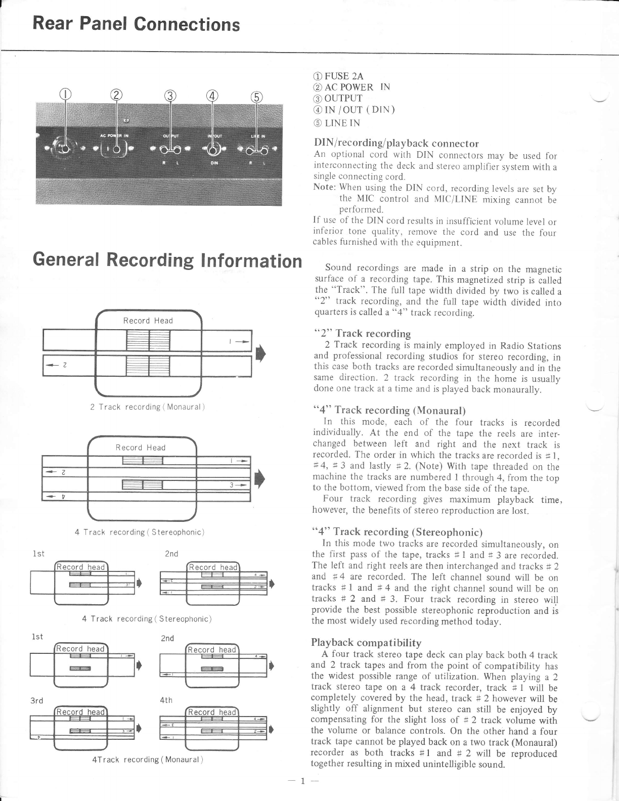
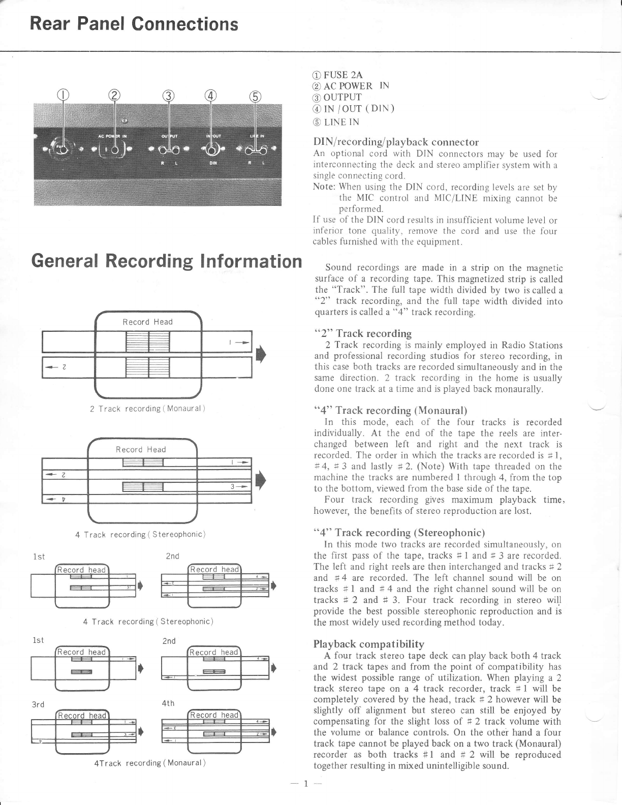
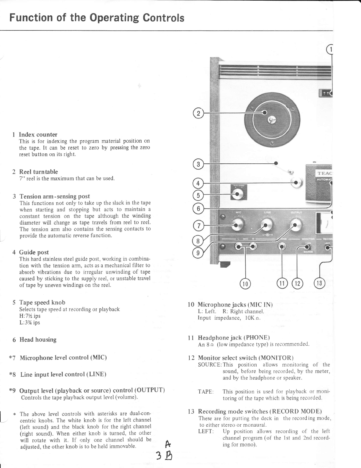
O FUSE 2A
(D AC POWER IN
o OUTPUT
@rN TOUT (DIN)
@ LINE IN
DIN/recording/playback connector
An optional cord with DIN connectors may be used for
interconnecting the deck and stereo amplilier system with a
single connecting cord.
Note: When using the DIN cord, recording leve1s are set
the MIC control and MIC/LINE mixing cannot
performed.
If use of the DIN cord results in insufficient volume level or
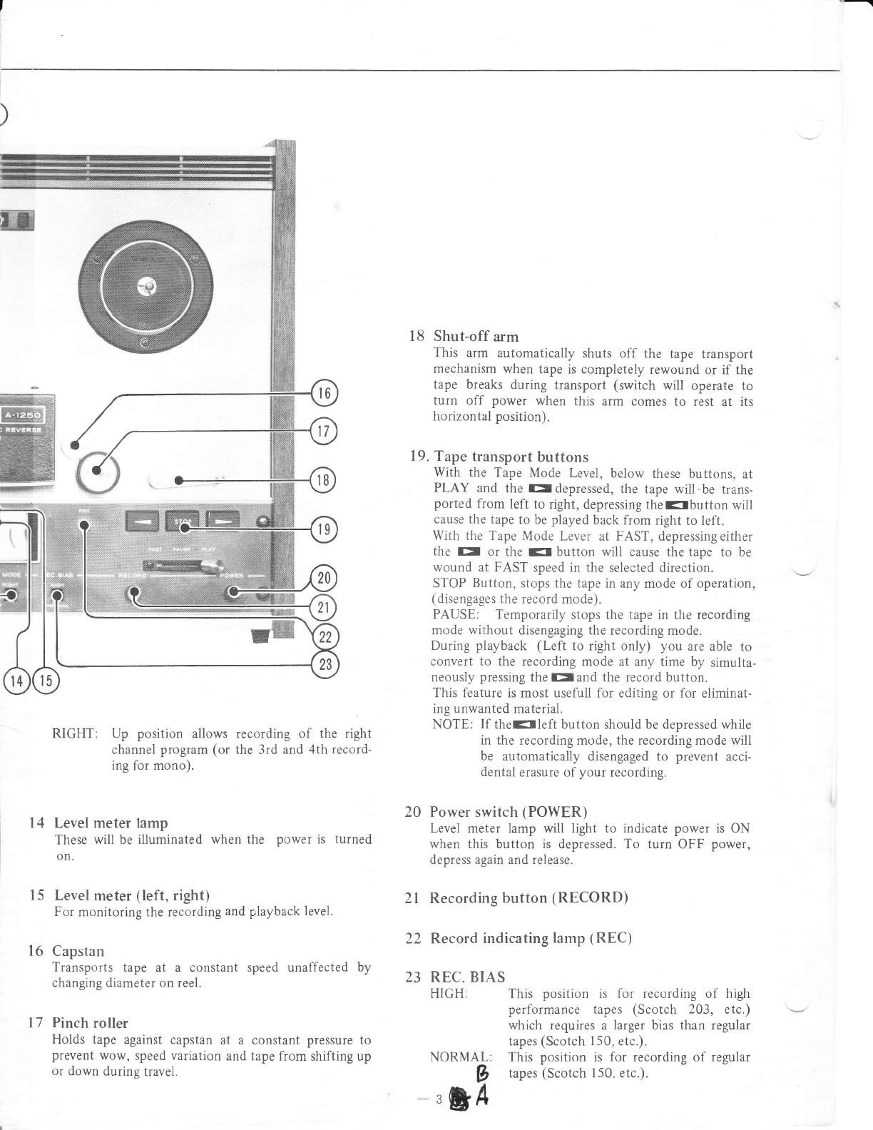
inlerior tone quality, remove rhe cord and use the four
cables furnished with the equiprrent.
Sound recordings are made in a strip on the magnetic
surface of a recording tape. This magnetized strip is called
the "Track". The lull tape width divided by two is called a
"2" track recording, and the full tape width divided into
quarters is called a "4" track recording.
"2" Tfack recording
2 Track recording is mainly employed in Radio Stations
and professional recording studios for stereo recording, in
this case both tracks are recorded simultaneously and in the
same direction. 2 track recording in the home is usually
done one track at a time and is played back monaurally.
"4" Track recording (Monaural)
In this mode, each of the four tracks is recorded
individually. At the end of the tape the reels are inter-
changed between left and right and the next track is
recorded. The order in rvhich the tracks are recorded is i* 1,
+ 4, # 3 and lastly # 2. (Note) With tape threaded on the
machine the tracks are numbered 1 through 4, from the top
to the bottom, viewed from the base side of the tape.
Four track recording gives maximum playback time,
however, the benefits of stereo reproduction are lost.
"4" Track recording (Stereophonic)
In this mode two tracks are recorded simultaneously, on
the first pass of the tape, tracks # I and S 3 are recorded.
The left and right reels are then interchanged and tracks # 2
and F 4 are recorded. The left channel sound will be on
tracks f I and # 4 and the right channel sound will be on
tracks f 2 and * 3. Four track recording in stereo wil,l
provide the best possible stereophonic reproduction and is
the most widely used recording method today.
Playback compatibility
A four track stereo tape deck can play back both 4 track
and 2 track tapes and from the point of compatibility has
the widest possible range of utilization. When playing a 2
track stereo tape on a 4 track recorder, track # 1 will be
completely covered by the head, track # 2 however will be
slightly off alignment but stereo can still be enjoyed by
compensating for the slight loss of f 2 track volume with
the volume or balance controls. On the other hand a four
track tape cannot be played back on a two track (Monaural)
recorder as both tracks # I and # 2 will be reproduced
together resulting in mixed unintelligible sound.
by
be
General Recording lnformation
4 Track recording ( Stereophonic)
2nd
1st lecord head
2 T rack recording ( Monaural )
Record Head
4 frack recording ( Stereophonic)
4Track recording ( Monaural )
-1--
Gonnections to and f rom the A-1 25O
Front of A-l 250
Microphone (right channel)
Microphone (lelt channel)
2
Stereo hcadphone/8 ohms
Function of the Operating Gontrols
Index counter
This is for indexing the program material position on
the tape. It can be reset to zero by pressing the zero
reset button on its right.
Reel turntable
7" reel is the maximum that can be used.
Tension arm - sensing post
This functions not only to take up the slack in the tape
when starting and stopping but acts to maintain a
constant tension on the tape although the winding
diameter will change as tape travels from reel to reel.
The tension arm also contains the sensing contacts to
provide the automatic reverse function.
Guide post
This hard stainless steel guide post, working in combina-
tion with the tension arm, acts as a mechanic-al filter to
absorb vibrations due to irregular unwinding of tape
caused by sticking to the supply reel, or unstable travel
of tape by uneven windings on the reel.
Tape speed knob
Selects tape speed at recording or playback
H:TLAips
L:33/+ ips
10 Microphone jacks (MIC IN)
L: Left. R: Right channel.
Input impedance, 10K o.
6 Head housing
*7 Microphone level control (MIC)
Line input level control (LINE)
Output level (playback or source) control (OUTPUT)
Controls the tape playback output level (volume).
The above level controls with asterisks are dual-con-
centric knobs. The white knob is for the left channel
(left sound) and the black knob for the right channel
(right sound). When either knob is turned, the other
will rotate with it. If only one channel should be
adjusted, the other knob is to be held immovable.
Headphone jack (PHONE)
An 8 o (low impedance type) is recommended.
Monitor select switch (MONITOR)
SOURCE:This position allows monitoring of the
sound, before being recorded, by the meter,
and by the headphone or speaker.
TAPE: This position is used for playback or moni-
toring of the tape which is being recorded.
Recording mode switches (RECORD MODE)
These are for putting the deck in the recording mode,
to either stereo or monaural.
LEFT: Up position allows recording of the left
channel program (of the 1 st and 2nd record-
ing for mono).
ll
l2
{€g
*9
L:*
A
3h
l3
RIGHT: Up position allows recording of the right
channel program (or the 3rd and 4th record-
ing for mono).
14 Level meter lamp
These will be illuminated when the power is turned
on.
Level meter (left, right)
For monitoring the recording and playback level.
Capstan
Transports tape at a constant speed unaffected by
changing diameter on reel.
Pinch roller
Hoids tape against capstan at a constant pressure to
prevent wow, speed variation and tape from shifting up
or down during travel.
18 Shut-off arm
This arm automatically shuts off the tape transport
mechanism when tape is completely rewound or if the
tape breaks during transport (switch will operate to
turn off power when this arm comes to rest at its
horizontal position).
19. Tape transport buttons
With the Tape Mode Level, below these buttons, at
PLAY and the Eldepressed, the tape will .be trans-
ported from left to right, depressing theEtbutton will
cause the tape to be played back from right to left.
With the Tape Mode Lever at FAST, depressing either
the El or the El button will cause the tape to be
wound at FAST speed in the selected direction.
STOP Button, stops the tape in any mode of operation,
(disengages the record mode).
PAUSE: Temporarily stops the tape in the recording
mode without disengaging the recording mode.
During playback (Left to right only) you are able to
convert to the recording mode at any time by simulta-
neously pressing the EIand the record button.
This feature is most usefull for editing or for eliminat-
ing unwanted material.
NOTE: If theEleft button should be depressed while
in the recording mode, the recording mode will
be automatically disengaged to prevent acci-
dental erasure of your recording.
22
Power switch (POWER)
Level meter lamp will light to indicate power is ON
when this button is depressed. To turn OFF power,
depress again and release.
Recording button ( RECORD)
Record indicating lamp (REC)
REC. BIAS
HIGH: This position is lor recording of high
performance tapes (Scotch 203, etc.)
which requires a larger bias than regular
tapes (Scotch I 50, etc.).
NORMAL: This position is for recording of regular
g tapes (Scotch 150. etc.).
21
15
l6
23
t7
-'GA
Integrated amplifier
Speaker system
(lelt channel) Speaker system
(right channel)
44,
Threading the Tape
)
Place lull reel .a onto the lelt reel turntable shaft b so
that the tape unwinds in the counterclockwise rotation'
In doing so, engage the three notches d at the center of
the reef with the three protrusions q at the bottom of
the shaft and press reel firmly onto turntable g.
lnstall reel clamp .t-- onto the lelt reel shaft .b-r to secure
the reel.
Secure end of tape onto empty reel (5,1 . Insert the end of
the tape into the notch on the reel while holding it
against the reel with your fingers and wind tape 2 or 3
times onto the reel hub -o-l .
Install reel clamp t) onto the right reel ,nug r-Bi' to firmly
hold down the empty reel. In doing so, be careful not to
pinch the end of tape with the clamp.
While holding the left reel '.4r so it will not move, rotate
the right reel tlt counterclockwise to take up slack in the
tape. The slack should be taken up sulficiently to bring
the shut off lever P to its limit to the left'
After these procedures, set the switch lever, below the
tape transport buttons, to PLAY and the tape deck is
now ready to start at any time by depressing the
t-> button.
@
CI
t
3
4Place an empty reel .hr on the right reel shaft g
Pull tl're .nO of tape with your fingers and
through each part in the order shown below' thread it
1) Tension arm O. 2) Lower side of guide post Q. 3)
Over the front faces of the head assembly (f . 4) Between
capstan fD and pinch roller @ . 5) Over the lower side of
the tape guide @ on the shut off lever. *4$
Basic Tape Deck Operation Playback of 4 Track Stereo
Tape
I
2Set TAPE SPEED knob to desired
Depress the POWER switch. tape speed.
3 Thread tape on the deck.
4 Set Tape Mode Lever to PLAY and then depress the
>button.The tape will then be transported from lett to
right at the previously set speed. Once thel:-.'button is
depressed the deck will continue to operate even though
the button is released. Depressing the -:-l button will cause
the tape to be played back from right to left.
Depress the STOP button and the tape will stop traveling.
Set the Tape Mode Lever to FAST, depress ther>fu11.t
and the tape will be wound at high speed (fast forward).
The TEAC A-1250 is an "Automatic reverse type" recorder.
It is not necessary to turn over the reels to play both sides
of the tape. At the end of the first two tracks the tape
direction will automatically reverse and playback of the
other two tracks will be accomplished. The automatic
reverse is accomplished by means of a conductive sensing
foil which should be applied as outlined below:
a. Cut a piece of sensing foil approximately 112 inch in
length.
b. Position the foil approximately 2 feet from the end of
the tape on the base side of the tape.
NOTE: l.The recommended sensing foil is "SCOTCH"
f51 sensingtape.
2. If the sensing foil is too short or too long, the
mechanism will not function properly.
3. The sensing foil must be precisely centered on
the base side of the tape so that no adhesive
surface of the sensing tape is exposed.
4. If the sensing tape is too close to the end of the
tape, the tape may become detached from the
reel hub before the reversing action takes place.
5. If the sensing contacts on the tension arm are
dirty or should the sensing foil become tarnish-
ed, proper reverse action cannot be expected.
Setting the stereo amplifier
When the Model A-1250 is connected to your amplifier
(refer to page 2) to playback tapes, fully retard the stereo
amplifier volume control and preset the switches as below:
Mode* selector: To STEREO (or to LEFT or RIGHT for
mono playback)
Tape monitorx switch: To TAPE
* These designations apply to TEAC amplifiers. Read the
Operating Manual of your amplifier or inquire of your
dealer if it is of other manufacture.
NOTE 1 For playback of mono tape, switch to the
LEFT channel for track 1 (1st playback) and
4 (2nd playback), and the RIGHT Channel
for track 3 (3rd playback) and 2 (4th
playback).
NOTE 2 - For setting the output level, adjust the stereo
amplifier volume control.
Tape speed. Set to "H" (7Yz ips) or "L" (33/a ips), to
match the speed at which the tape was
recorded.
At playback of a high level recorded tape, adjust VOLUME
control so as not to scale out the level meter pointers.
tr
5
6
7 Depressing the -J button will fast rewind the tape.
(In the above operation, always depress the STOp
button before reversing direction of tape travel or tape
may break).
Playback of 4 Track Mono
Tape
I Set MONITOR switch to TAPE
2 Adjust playback level control (OUTPUT) knobs (white
lor L; black lor R) to the desired level.
3 Set Tape Mode Lever to
button. PLAY and depress the
Advance the OUTPUT knob clockwise and adjust so that
the level meter indications (both lelt and right) at
maximum will be under O VU.
To balance the left and right meter indications, separately
adjust the OUTPUT knobs-the black knob for the right
channel and the white knob for the left channel.
Your stereo amplifier volume control is adjusted for final
speaker voiume adjustment.
1 Set MONITOR switch to TAPE.
Adjust the white L knob of the playback level control
(OUTPUT) to a suitable level. The black R knob should
remain at the fully counterclockwise position.
Set Tape Mode Lever to PLAY and depress ther> button
4 The white L knob only of the OUTPUT'knob is adjusted
and set so that the left channel level meter pointer
deflection at maximum is below O VU.
5 Your stereo amplifier volume control is adjusted for final
speaker volume adjustment.
Continuous playback of multi-channel mono tape
At playbacli ol a 4 track or 2 track monophonic tape, all
of the tape after completion of the first track will be wound
onto the right reel, at which tirne the tape deck will
automatically shut off. Both the left and right reels are
removed, interchanged between the left and right, the reels
mounted on the turntable, rethreaded on the deck, and
playback continued of track 4, or the opposite track of a 2
ituik .ono tape. On a 4 track mono tape, this is repeated
three times to playback the tracks in the 1, 4,3,2 ordet'
Upon finishing playback of tracks I and 4, the left channel
OUfpUf tnoU is fully retarded and the rear R knob
advanced to playback tracks 3 and 2.
Playback Operation Chart, 4 Track Mono Tape
Playback order lsl ?rd 3rd ,1!h
Fr)r Dlavbeck of track 3
Tape m,'de le PLAY PLAY PI-AY PLAY
OUTPLIT knob Position al Lr)W(while) LOW (white) ARLL (black AR(lF: lblack
Lcv-"1 Lefl Left tush1 Rrghl
oil'fPUT channcl Left t€11 Rrght Rishl
-6-
Splicing the Tape Expert Use of Rec. Bias and
Pause
\2
/-7-'-7----l
REC. BIAS
Generally, for recording on regular tapes (Scotch 150;
BASF LP-35; Agfa PE-31; SONY S-100; etc.), the REC
BIAS should be set to NORMAL.
When recording high performance tapes (Scotch 203;
BASF- LP-35LH; Agla PB-36; SONY SLH-550; etc') which
require a larger bias tlian regular types, always set the REC'
BIIS switch to HIGH. This will allow taking complete
advantage of all the merits of a high perfomance tape at
recording wide range, high SN ratio, large output, low
distortion and witie dynamic range
NOTE: Not only will the l'righ notes be exaggerated and
sound balance destroyed when a recording is made
on a high performance tape at the NOR\IAL
setting of the switch but distortion will increase
and tire sound will be unnatural.
Also, in the opposite situation--if a regular tape is
recorded with the switch remaining in the HIGH
position, balance will be destroyed with lack of
high notes, and moreover, the recording level rvill
be low and sound unnatural'
EXPERT MONITORING AT RECORDTNG ON
LOW NOISE TAPE
Although therc will be no difference in sound level, when
recording on regular tape, if the tape MONITOR switch is
set to either SOURCE or TAPE, there will be difference in
sound volume (including meter level difl'erence) between the
source ancl tape wl.ren using low noise tape (sound volume
will be lower on the TAPE position but this is due to
difference in tape sensitivity). If you wish to compare sound
between the source and tape at the same sound 1evel,
advance the OUTPUT knob to match sound level with that
from the source while the Tape Monitor Switch is in the
'I'APE position or, use the tape monitor switch on your
amplifier to which this tape deck is connected' When using
this switch, set the tape deck MONITOR switch to TAPE
and match the sound volume with the OUTPUT knob.
PAUSE
In conventional tape decks, recording is started by
depressing the recording button and then the 'play' button
bui the Model A-1250 features a unique recording system
permitting the use of "PAUSE" during recording a "com-
mercial killer."
During recording, the tape can be stopped by setting the
Tape Mode Lever to "PAUSE" to start again when the Lever
is set to "PLAY" thus permitting one-touch start of the
tape. Also, if you should wish to switch to the recording
mode during playback, the Lever is set to PAUSE, and by
depressing the-RECORD button and then the : '-button, the
taie deck will be placed in the recording mode, ready to
begin recording as soon as the lever is set to PLAY'
Furthermore, if you wish to record or erase the tape during
playback without stopping it, the tape deck-can be put in
ihe recording mode by simultaneously depressing the
RECORD and t,> button.
Should your tape be broken or should you desire to edit a
tape, use the procedures outlined below'
Scissors ; Ctmpletely demagnetize the scissors by use of
the tlead or Bulk demagnetizer. LIse of a magnetized scissors
wi-ll result in a "Click" at the spliced area'
Splicing tape : Use only a commercial splicing tape' Never
use CelJphane (Scotch) iup. ut the adhesive will spread and
contaminate your recording heads.
Method of splicing: Overlap the ends to be spliced by
approximately ''Linci,align them carefully then cut through
the center ofihe overlapp.d.rea at a 60" angle' The ends of
the slanted cut tape aie then butted together and the
splicing tape applied to the base side t-rf the tape' T-o insure
firm .f,f,.i.n.., tttt splice is placed on a hard surface and
the splicing tape rubbid briskly wilh your fingernails or any
hard smooih obiect. Next trim off any excess splicing tape'
cut slightly into the tape on both edges at the spliced area'
(See illustration)
General lnformation and Precautions at Recording
The tape
The length of a recording tape as well as the recording
time, is determined by the reel diameter and the thickness
of the base material.
Tlre use of a 1 or 1% mil base tape is recommendcd lor 4
track high fidelity recording. Polyester base tape is preferred
for use in humid or extromely dry areas.
Tlrree recording speeds are commonly used, 3'\/q, and l/2
incl'res per second.
71/z ips is commonly used for home high lidelity
recording. Gcncrally speaking, the higher the recording
Good quality tape wound on correct reel
Tape condition can be judged by the appearance
when wound on the reel and viewed from the side
1) Is it neatly wound? 2) Is there steps or irregularities in
the winding? 3) Is the color of base uniform as seen from
the side? 4) Is the tape edge smooth?
Spots seen
sound). on the edge indicate 'drop but' (skipping of
speed, tl.re better the fidelity. Howevei, due to the extreme-
ly high quality of the TEAC tape decks, recordings of
excellent quality can be made at the lower speeds. This
provides maximum tape economy and extended playing
time.
The recording time indicated in the chart below is for one
single pass of the tape, therefore the total recording time
will either two or four times that indicated, depending upon
the method of recordins.
Selecting the tape and reel
For recording, new tape is not necessarily needed as long
as it is of good quality as the erase head will erase the
previous recording as the new recording is made. However,
avoid using tapes whose coating is worn, peeled off or
stretched.
If the color ot'the winding is different throughout the
reel it is an indication that two different types of tape have
been spliced in. In some cases, the color may differ
according to production lot even for the same type tape, or
between opposite sides of the wound tape.
Judging tape condition by how it travels
Head
Creases extending from the center positively indicate uneven
stretching. This is caused by diflerences in temperature and
humidity. \v
Fungus indicates old tape stored for a length of time under
high humidity. Sections where the splicing tape has been
applied are especially prone to support fungus growth.
Tapes which snake up and down between the guides and
ove, ihe heads will inevitably lead to level fluctuations and
azimuth misalignment. Head Pinch roller
Unevenly stretched tape which travels either higher or
lower than the true path of the tape will in extreme cases
drift ofi the pinch rolle,r.
Head
Capstan
Snaky motion of unevenly stretched tape indicated by
arrows.
track tape brands on market
Recordins time
I aPe rengtlr 1% ip\T"*/A ips BASF Agfa SONY
37Om 1200 ft 30 min. 60 min.
-----l-
550m 1800 lt 45 min.;90 min. o 190
Standard Polyester 52 p l% mll
sz u r4rrltt
35y lmilLong play I Acetate
L""g pl.tl P"lymt.t
Long piay Polyester
Double play
35 tt 1 mil
35p lmil
28 p ',4 mtl 60 min,
8-
7
Normal condition reel
The use of a good qual:ity reel is an
preventing damage to the tape edge or
Always use reels of the same diameter.
Reels which damage tape
The reel may be wiirped in
winding. This will nol ocrur ir)
whose hub is perfectly fitted.
important point in
uneven stretching.
a Yo-Yo shape due to tight
re:ls made ol hard plastic or
Re.els warped in the shape of a bowl will bend the tape,
resulting in the so-called uneven stretcl'ring. and is sometimes
encountered even in new reels.
Skillful setting of recording level
Two important factors are required in a good sound tape.
One is that the frequency range be wide and the other is
that it has a minimum of distortion and noise.
Although the frequency response is actually determined
by the tape deck perlormance characteristics and quality of
the tape used, variation ol the recording level has a great
aflect on the end result.
ln order to make a recording with minimum noise, it is
desirable to record at tl're highest possible level just before
distortion is ir:rtroduced. Even then, it is not always
necessary to record at the maximum volume level ol the
music or to maintain the level meter indication at thg
dividing line between the red and black zone (0 Vtr. It
must be kept in mind that any tape will suddenly increase in
distortion. and recording sensitivity ol the high notes will
slightly decrease wl'ren the recording Ievel exceeds a certain
point. For this reason. a standard level of 0 dts is established
with an ample margin ol saletl taken into consideration. In
actuality. it is best to become fully acquainted with the
performance of tl.re tape and the deck you are using before
determining the operating level.
Experimentation while using the "Monitor" leature wrll
quickly acquaint you with the best recording level for the
type tape you are using.
If the hub is not truly perpendrcular to the flange, the
wound tape will be pressed against the flange resulting in a
seaweed form of tape.
Hang down a length of tape to check straightness
ln ll
XXXXO
Selecting tape speed
Two different tape
L=9.5cms (3% ips) can
A- l 250.
The 19cm speed is suitable lor hi-fi recording of music
and the 9.5cm speed is used for Back Ground Music and
speech recordings.
As the 9.5cm recording speed provides twice that of the
19cm speed in recording time, if the sound quality is
satisfactory at this speed it will be more economical.
The level of quality desired in the finished recording will
determine which speed you should use.
speeds, H=i!.*, (7% ips) and
be selected on the TEAC Model
R.lrlrif tjr ror\'ro re.orJLnt tapl
tr!
tl
]!
lq
1C
50
9
Recording in 4 Track Stereo
All recording with the A-1250 is accomplished from the left
reel to the right. At the completion of the first two tracks,
the reels are interchanged and the remaining two tracks are
recorded. At this time you may affix the sensing tape and
you ale equipped for playback in either dtrection. The
automatic reverse will function at the end of side one (the
first two recorded channels) to reverse the direction of tape
travei, play back the remaining two channels and the
recorder will stop when the second two channels have been
played through.
Recording with microphones
Plugs from the two microphones are plugged into the
microphone jacks (MlC L, R) on the front panel-the left
microphone plug into L, and the right one into R. The
microphone recording levels are controlled by the MIC knob
above. Use a microphone with an impedance of 10K o or
lower. A 600o microphone can also be used.
Recording from a phono player, tuner, tape, etc' -
REC. O-UT from your stereo amplifier or preamplifier
outputs from your phono player, radio tuner, tape player
and others must all go to the LINE IN jacks ( refer to page
2). Recording level ol signals to LINE IN are controlled by
the LINE knob on the front Panel.
Sound mixing of mic. with the phono player, tape
or other sound
With the microphones plugged into MIC lN and the
proper sources into LINE IN, each signal is controlled by
iheir respective knobs to set the recording level'
Set the TAPE SPEED knob to desired speed and thread
tape.
Set the MONITOR switch to SOURCE.
3 Set the MIC or LINE level controls so that the meter
pointer does not scale out even at maximum sound
volume (recording level adjustment). Sound volume of
LINE OUT and PHONE is controlled by the OUTPUT
knob.
(l) Speaker volume is controlled at your stereo amplifiet.
When recording with a microphone, the speaker sound
will feedback through the microphone to cause un-
pleasant howling. In such a case, place the microphone
away from the speaker or turn down speaker volume to
zero and use a pair of headPhones.
(2) To balance the left and right levels, individually adjust
the white and black level controls so that the left and
right level meter readings will be almost the same at
peak levels.
4 Switch on both the LEFT and RIGHT switches of the
RECORD MODE. If the tape to be used is of the high
performance type requiring a larger bias than regular
types, set the REC. BIAS to HIGH.
5 Put the Tape Mode Selector Lever to PLAY' Then,
recording will begin when the button is depressed while
the REC. button is being depressed.
5 In the middle of a recording, if you wish to cut off a
commercial, the tape will momentarily stop when the
i;;; ;; put to PAUbE and start again when it is returned
to PLAY.
7 Sound recorded on the tape can be monitored during
recording by setting the MdNITOR switch to TAPE and
advancing the OUTPUT knob'
If thebUTPUT knob is adjusted and set to match in
level with that of the SOURCE on the meter'' the
,ecorAing level can also be monitored at the TAPE
position of the switch'
8 At the end of the tape, the left and right reels, are
- int.r.t unged, and the above procedtires repeated to
continue recording on the tracks'
-10-
Recording in 4 Track Mono
Recording with a microphone
When using one microphone, it is first plugged into the
LEFT-MIC jack. The recording level of the microphone is
controlled by the white (L channel) MIC knob.
Recording from a phono player, tuner, tape, etc.
Preamplifier outputs from the phono player, tuner, tape
player are first plugged into the L jack of the LINE IN. In a
stereo amplifier, the connection remains as it is and the
MODE SELECTOR is switched so as to send only the left
channel signals to the tape deck ( refer to your stereo
amplifier Operating Manual). The line recording level is set
by the white (L channel) knob of the LINE control.
* The black (R channel) knob is fully retarded.
Sound mixing of mic. with the phono player, tape
or other sound
With the microphone plugged into MIC IN and the proper
sources into LINE IN, each signal is controlled by their
respective knobs (white L knobs only) to set the recording
signal level.
Set the TAPE SPEED knob to desired speed and thread
tape on the machine.
Set the MONITOR switch to SOURCE.
3 Set the MIC or LINE level control (white L knobs only)
so that the level meter indicates 0 VU at peak levels.
Be careful of howling (refer to page 10, recording in 4
track stereo, item 3-l).
4 Switch on the LEFT channel of the REC. MODE. If the
tape to be used is of the high performance type requiring
a larger bias than regular types, set the REC. BIAS to
HIGH.
5 Put the Tape Mode Selector Lever to "PLAY." Then,
recording will begin when the i -- button is depressed
while the "REC." button is being depressed.
6 In the middle of a recording, if you wish to cut off a
commercial, the tape can be momentarily stc,rpped by
putting the Lever to "PAUSE" and started again by
returning it to "PLAY".
7 Sound recorded on the tape can be monitored during
recording by setting the MONITOR switch to TAPE and
advancing the OUTPUT knob (white L knob only).
Ii the OUTPUT knob is adjusted and set to match in
level with that of the SOURCE on the meter, the
recording level can also be monitored at the TAPE
position of the switch.
8 At the end of the tape (at finish of track 1), to continue
recording (on track 4 which is on the opposite side of
track 1 and in the other direction) the left and right reels
are interchanged and the tape restarted in the recording
mode.
9 Track 3 is recorded next, with the full reel again on the
left. But this time. srvitch on the RIGHT channel of the
REC. NIODE and arrange that all the sources come
througl'r RIGHT channel. The completion ol the program
may be recorded on Track 2 by again turning the reels
over.
- 1l--
Recording Sound-on-Sound
Sound-on-sound and language training can be done on the
Model A-1250 Stereo Tape Deck.
A preliminary mono recording on track I (left channel) is
played back, mixed with sound from the microphone and
re-recorded on track 3 (right channel).
For instance, a one person duet or trio with accom-
panying music in the background (Sound-on-Sound) can be
made, or the teachers pronunciation and the students voice
can be recorded together during language training.
Music (or the teachers voice) which is to be recorded first
is put on track I (refer to Mono Recording, page I 1)'
(t) nt tne beginning of recording. reset the index counter
to zeto to indicate start of recording'
(2) Upon starting the iape. the playback rs-nonitored
' (MbNITOR set to TAPE) and the OUTPUT knob set
(ro that the left channel level meter indicates a
maximum of 0 VU).
On finishing the track I recording, rewind tape- to start of
recording. Switch OFF the LEFT channel of the REC'
Knob R (black knob) is used at playback after finishing
recording.
** Knob L (white knob) is used at playback after finishing
recording.
Gorrecting the Reel
Turntable Height
There is a Philips head screw at the end of both the lelt and
right turntable shafts. Using a Philips screwdriver' rotate it
cJunterclockwise and the turntable will rise. Adjust this to
it. rnott zuitable height. This adjustment can also be made
with the reel and reel clamper attached'
MODE.
J Interconnect the OUTPUT-L and LINE IN-R jacks on the
rear of amplifier with a connecting cable'
4 Plug a heidphone into the PHONE jack and the micro-
phone into the MIC-R jack.
5 bet Lever to the PLAY position' switch ON the RIGHT
of REC. MODE, and the tape will start recording when
the r= button is depressed while depressing the REC
button.
6 While listening to the playback of track I with a
headphone (lelt ear only), and using the right channel
MIC' and LINE knobs (white L channel) mix the
microphone sound (the students voice. for language
training) for the second recording with the sound from
track I and record on track 3.
7 On finishing the recording, rewind the tape to the start
and play baik the right channel (track 3)'
If the results are unsatisfactory,'the same recording
onto track 3 .can be repeated as many times as
necessary siirce the original recording still remains on
track 1.
Sound-on-Sound Recording Step Chart
lst 2nd 3rd
MIC IN or LINE IN iack LRL
MIC or LINE knob LRL
MONITOR switch SOURCI
and
TAPE TAPE TAPE
Level meter Left Risht Left
REC. MODE switch Irft Risht trft
OUTPUT knob LLR
Headphone L€ft Left Right
-12-
Erasing Demagnetizing
ilre
The head line-up of the Model ,4-1250 as seen front the
lront is as shown in the photo.
Since the recording head .functions throughout the
recording mode, il a pre-recprded tape is used for recording,
the old recording will be erased frrst by the erase head and a
new recording made at the recording head.
To erase all recordings
To only erase the tape, the MIC and LINE knobs are lully
rotated counterclockwise to prevent any sound from being
recorded, the tape started in the stereo recording mode, 2
tracks (tracks I and 3) will be erased. After completing
erasure of the first two tracks, the reels are interchanged and
the above procedure repeated. This will erase the remaining
two tracks (tracks 4 and 2).
To efficiently erase old recordings from tape in a few
seconds, the use of the TEAC Model E'2 Tape Eraser is
recommended.
Model E-2 Tape Eraser
To erase a section of a recording
1 Switch on either or both the LEFT and RIGIIT ol the
REC. MODE and start the tape in the playback mode by
depressing the button (do not depress the recording
button yet). When the portion to be erased arrives
simultaneously depress the RECORD and -- buttons.
2 As soon as the last part of the section to be erased passes
the erase head, quickly depress the STOP button. Be
extremely carelul not to erase more than intended which
may happen if you should miss correctiy timing the
instant to depress the RECORD button,;---button, and
the STOP button.
Precaution at stop-and-go recording
When you do intermittent stop-and-go recording on old
recorded tape, a portion ot' the old recording will rernain
unerased at the point where the STOP button is depressed.
To prevent such fault, always completely erase the tape of
old recordings before you start recording.
During long perrods of use, the heads will become slightly
magnetized. As a result, the high frequency will decrease.
noise will develop, or in extreme cases the high regions will
drop out or introduce noise into your valued pre-recorded
tapes. To keep your recor,ler operating at optimum effi -
ciency the heads should be demagnetized at least once for
every 50 hours of use, with a TEAC Model E-l Head
Demagnetizer, using the procedures outlined below:
1 Turn oll power to the tape deck.
2 Attach the plastic protectors on .the pole tips of the
Demagnetizer.
3 Plug the Demagnetizer cord into an A.C. outlet.
-1 Depress the Demagnetizer power button, bring the tip
close to the head and siowly move it up and down 4 or 5
times.
5 Slowlv draw it away from the head.
6 After finishing the above procedure on each head, turn
otf power to the Demagnetizer ONLY after it has been
drawn at least l2 inches away from the heads.
7 The same demagnetizing procedure is lollowed on each
head. capstan shaft, and the guide posts.
Model E-1 Head Demagnetizer

Other Teac Tape Deck manuals

Teac X-300R User manual

Teac

Teac X-300R User manual

Teac A-6100MKII User manual

Teac

Teac A-6100MKII User manual

Teac A-4000S User manual

Teac

Teac A-4000S User manual

Teac A-6010GSL User manual

Teac

Teac A-6010GSL User manual

Teac A-2500 User manual

Teac

Teac A-2500 User manual

Teac A-6600 User manual

Teac

Teac A-6600 User manual

Teac A-3300SR User manual

Teac

Teac A-3300SR User manual

Teac A-2340 User manual

Teac

Teac A-2340 User manual

Teac A-3300SX User manual

Teac

Teac A-3300SX User manual

Teac X-7RMKII User manual

Teac

Teac X-7RMKII User manual

Teac AL-700 User manual

Teac

Teac AL-700 User manual

Teac A-6010GSL User manual

Teac

Teac A-6010GSL User manual

Teac 3340S User manual

Teac

Teac 3340S User manual

Teac A-2340 User manual

Teac

Teac A-2340 User manual

Teac A-4300SX User manual

Teac

Teac A-4300SX User manual

Teac A-4300SX User manual

Teac

Teac A-4300SX User manual

Teac A-3300SR User manual

Teac

Teac A-3300SR User manual

Teac X-2000R User manual

Teac

Teac X-2000R User manual

Teac X-300R User manual

Teac

Teac X-300R User manual

Teac X-3R User manual

Teac

Teac X-3R User manual

Teac A-6300 User manual

Teac

Teac A-6300 User manual

Teac A-3440 User manual

Teac

Teac A-3440 User manual

Teac X-300R User manual

Teac

Teac X-300R User manual

Teac A-3440 User manual

Teac

Teac A-3440 User manual

Popular Tape Deck manuals by other brands

Broadcast Electronics 3000 Series instruction manual

Broadcast Electronics

Broadcast Electronics 3000 Series instruction manual

Akai GX-77 Service manual

Akai

Akai GX-77 Service manual

Technics RSTR155 - DUAL CASS RECORDER operating instructions

Technics

Technics RSTR155 - DUAL CASS RECORDER operating instructions

Pioneer CT-1150R operating instructions

Pioneer

Pioneer CT-1150R operating instructions

Revox B215 operating instructions

Revox

Revox B215 operating instructions

Kenwood KX-W4040 instruction manual

Kenwood

Kenwood KX-W4040 instruction manual

Pioneer RT-1011L Service manual

Pioneer

Pioneer RT-1011L Service manual

Sony TC-388-4 Service manual

Sony

Sony TC-388-4 Service manual

NAD 613 Service manual

NAD

NAD 613 Service manual

Kenwood KX-94W Service manual

Kenwood

Kenwood KX-94W Service manual

Kenwood KX-5550 instruction manual

Kenwood

Kenwood KX-5550 instruction manual

Pioneer XC-IS21T Service manual

Pioneer

Pioneer XC-IS21T Service manual

Salora SV8720 Service manual

Salora

Salora SV8720 Service manual

Akai GX-270D Quick reference guide

Akai

Akai GX-270D Quick reference guide

Rotel RD-845 owner's manual

Rotel

Rotel RD-845 owner's manual

Pioneer CT-055W operating instructions

Pioneer

Pioneer CT-055W operating instructions

Robopac ROBOTAPE 50 CFA Use and maintenance manual

Robopac

Robopac ROBOTAPE 50 CFA Use and maintenance manual

Pioneer CT-9R Service manual

Pioneer

Pioneer CT-9R Service manual

manuals.online logo
manuals.online logoBrands
  • About & Mission
  • Contact us
  • Privacy Policy
  • Terms and Conditions

Copyright 2025 Manuals.Online. All Rights Reserved.