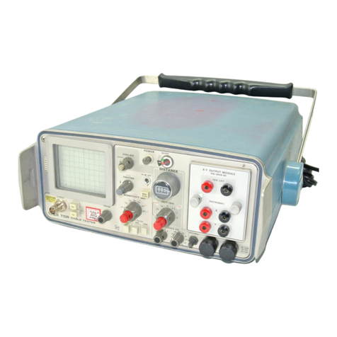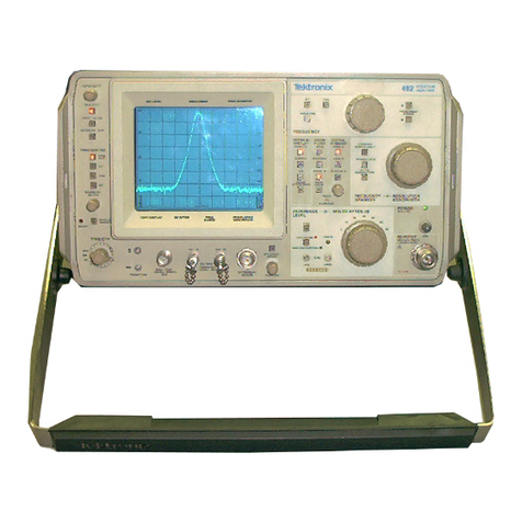
495/495P Operators
TABLE
OF
CONTENTS
Page
PREFACE
......................
......
.........................................
i
TABLE OF CONTENTS
.....................
..
.........................
ii
LIST OF ILLUSTRATIONS
...................
..
......................
iv
LIST OF TABLES
.............................................................
v
SAFETY SUMMARY
.....................
...
..........................
vi
Section 1
Section
2
Section
3
Section
4
GENERAL INFORMATION
Product Overview
....................................
1-1
Firmware Version and Error Message
Readout
..............................................
1-1
Accessories
........................................
1-1
Options
........................
..
...................
1-2
SPECIFICATION
Electrical Characteristics
.........................
2-1
Verification of Tolerance Values
..........
2-1
Frequency Related Characteristics
.....
2-1
Amplitude Related Characteristics
......
2-4
Input Signal Characteristics
................
2-8
............
Output Signal Characteristics 2-1
0
General Characteristics
.....................
2-11
Power Requirements
.........................
2-11
Environmental Characteristics
...........
2-12
Physical Characteristics
....................
2-13
PREPARATIONFOR USE
Unpacking and Initial Inspection
..............
3-1
Installation
.............................................
3-1
Rackrnount Instrument
........................
3-1
Rack Adapter Kit
.........................
.....
3-2
Power Source and Power
Requirements
....................
..
.................
3-2
Storage and Repackaging
.......................
3-2
Storage
...............................
........
........
3-2
Repackaging for Shipment
..................
3-2
Transit Case
...............
.......
............
3-2
CONTROLS. CONNECTORS.
AND INDICATORS
....................................
Operating Modes 4-1
Initial Entry Functions (Black Labels)
..
4.1
Multiple-Pushbutton Sequence
Functions (SHIFT Pushbuttons)
..........
4-1
Terminating Multiple-Pushbutton
Sequences
.......................................
4-1
DATA ENTRY Functions (Orange
Labels)
..............................
..
............
4-2
Page
Section
4
(continued)
Correcting Numerical Entry Errors
......
4-2
lnstrument Power Control and
Frequency
................................................
4-3
Frequency Span and Resolution
..............
4-5
Marker Functions
...................
...
........
4-7
Display Parameters
...............................
4-14
Sweep
...............................................
4-17
Digital Storage
.......................................
419
Display and General Purpose
................
4-21
Front-panel Input/Outputand GPIB
.......
4-24
Rear-panel Input/Output and GPIB
........
4-26
Section
5
INSTRUMENT CHECK OUT
Firmware Version and Error Message
Readout
................................................
5-1
Firmware Version
................................
5-1
Error Message Readout
......................
5-1
Preparation for Use
.................................
5-1
1
.
Initial Turn On
...............................
5-1
2
.Calibrate Position. Center
Frequency. Reference Level. and
Bandwidth
...........................................
5-2
Functional or Operational Check
.............
5-3
Equipment Required
..............
...
.......
5-3
Preliminary Preparation
......................
5-3
1
.
Check Operation of Front-Panel
Pushbuttons and Controls
...................
5-3
2
.
Check Gain Variation Between
Resolution Bandwidths
.....................
5-10
3
.
Check Span Accuracy and
Linearity
..........................
.............
...
5-11
4
.
Check Resolution Bandwidth and
.............
.................
Shape Factor
..
511
5
.
Check Reference Level Gain and
RF Attenuator Steps
.........................
5-12
6
.Check Sensitivity
.........................
5-12
7
.
Check Residual FM
.......................
5-13
8
.
Check Frequency Drift or
.............................................
Stability 3
9
.
GPlB Verification Program
............
5-13
Section
6
OPERATION
Instrument Operating Features
................
6-1
Firmware Version and Error Message
Readout
..............................................
6-1
Crt Light Filters
...................................
6-1
Intensity Level and Beam Alignment
...
6-1
Signal Application
...................
..
.......
6-1
A
RF INPUTConnector
.....................
6-1
iii
