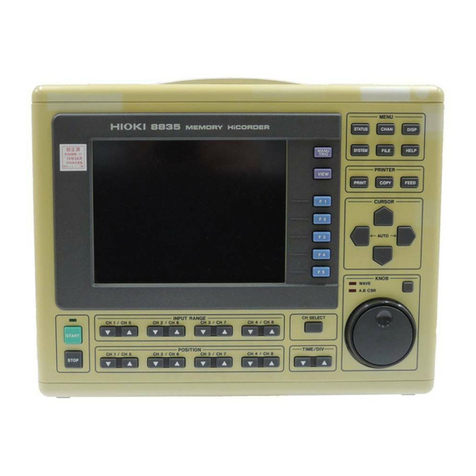
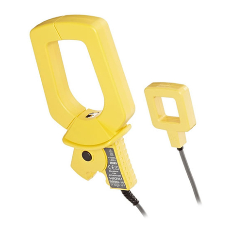
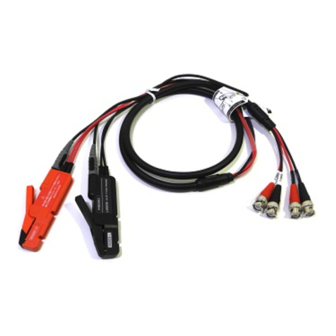
Hioki 3196 Instruction manual

POWER QUALITY
QUICK START MANUAL
3196
ANALYZER


Contents i
1
2
3
4
5
6
7
8
9
10
11
APPX
IDX
Contents
Introduction .................................................................. 1
Standard Accessories and Options ..............................1
Safety Notes ................................................................ 4
Usage Notes ................................................................ 7
Reading the Operation Procedures ...........................12
1 Overview 13
1.1 Product Overview .............................................13
1.2 Features ...........................................................14
2 Parts Names 19
2.1 Instrument Labels and Functions .....................20
2.2 Screen Names and Display Elements ..............24
2.2.1 Common Display Elements ...............................25
3 Measurement Preparations 29
3.1 Connection Procedure ......................................29
3.2 Attaching the Strap ...........................................30
3.3 Installing the Battery Pack ................................31
3.4 Connecting the AC Adapter .............................. 32
3.5 Connecting the Voltage Cords ......................... 33
3.6 Wiring Adapter Connection (Option) ................ 35
3.7 Using a Clamp-On Sensor (Option) ................. 37
3.7.1 Clamp-On Sensor Specifications .......................38
3.7.2 Connecting a Clamp-on Sensor ........................41
3.8 Turning the Power On/Off ................................42

Contents
Quick Start Manual
ii
4 Connecting to Lines to be Measured 45
4.1 Connection Procedure ......................................45
4.2 Connection Methods ........................................46
4.2.1 Single-Phase System Connections ...................47
4.2.2 Connecting to Multiple Systems ........................49
5 Quick Reference 51
5.1 Connection and System Settings .....................51
5.2 Data Display .....................................................52
5.3 Data Recording, Saving, Loading and Deleting 53
5.4 Event Analysis ..................................................54
5.5 Using Peripheral Devices .................................55
6 Measurement Method 57
6.1 Checking Three-phase Systems ......................57
6.2 Change in Power .............................................. 64
6.3 Harmonic Fluctuation ....................................... 70
6.4 Monitoring Interruptions ....................................78
6.5 Detecting Transients and Waveform Distortion 88
6.6 ∆V10 Flicker ..................................................... 96
6.7 IEC Flicker ...................................................... 102
7 Peripheral Devices 109
7.1 Using a PC Card ............................................ 109
7.2 Using a Printer (Option) ..................................116
7.3 Using the Instrument with a Computer ........... 121
7.3.1 RS-232C Connection .......................................122
7.3.2 LAN Connection ..............................................123
7.4 Using the External Control Terminals ............. 124

Contents iii
1
2
3
4
5
6
7
8
9
10
11
APPX
IDX
8 Specifications 125
9 Maintenance and Service 137
9.1 Cleaning and Storage ..................................... 137
9.2 Repair and Servicing ...................................... 138
9.3 Battery Pack Charging ................................... 139
9.4 Battery Pack Replacement and Disposal ....... 140
9.5 Instrument Disposal ........................................ 141
Appendix 143
Troubleshooting ....................................................... 143
FAQ .......................................................................... 145
Reference ................................................................ 146

Contents
Quick Start Manual
iv

Introduction
1
2
3
4
5
6
7
8
9
10
11
Introduction
1
Introduction
Thank you for purchasing the HIOKI “3196 POWER QUALITY
ANALYZER”. To obtain maximum performance from the product,
please read this manual first, and keep it handy for future refer-
ence.
• Refer to the Instruction Manual (CD-R version) provided with this
device.
• For current input with this device, a clamp-on sensor (optional) is
required. For details, refer to the instruction manual for the
clamp-on sensor you are using.
• For detailed information on the EN50160, see the Instruction
Manual for EN50160.
Standard Accessories and Options
Checking the contents of the package
When you receive the product, inspect it carefully to ensure that no
damage occurred during shipping. In particular, check the accesso-
ries, panel switches, and connectors. If damage is evident, or if it
fails to operate according to the specifications, contact your dealer
or Hioki representative.
9
458 AC ADAPTER
(
power cord included)
Input Cord Label
(For distinguishing the voltage cord
and clamp-on sensor channels.)
9438-02 VOLTAGE CORD
1 set (8 cords)
(One each red, yellow, blue, and
gray cord, and four black cords.)
Strap
3
196POWERQUALITY
A
NALYZER
• Quick Start Manual
• Instruction Manual
for EN50160
Software (CD-R)
• Instruction Manual
• Instruction Manual for EN5016
0
• "Down96" Data Download
Application Software
LAN Connector
Cover
9459 BATTERY PACK
(7.2 V, 2700 mAh)

Standard Accessories and Options
2Quick Start Manual
Before using the 3196
• Before using the product the first time, verify that it operates nor-
mally to ensure that the no damage occurred during storage or
shipping. If you find any damage, contact your dealer or Hioki
representative.
• Before using the product, make sure that the insulation on the
9438-02 VOLTAGE CORD is undamaged and that no bare con-
ductors are improperly exposed. Using the product in such con-
ditions could cause an electric shock, so contact your dealer or
Hioki representative for repair.
Shipping precautions
Use the original packing materials when reshipping the product, if
possible.
Options
Clamps • 9660 CLAMP ON SENSOR (100 A rms rating)
• 9661 CLAMP ON SENSOR (500 A rms rating)
•
9667 FLEXIBLE CLAMP ON SENSOR
(500 A rms, 5000A rms rating)
• 9669 CLAMP ON SENSOR (1000 A rms rating)
• 9694 CLAMP ON SENSOR (5 A rms rating)
• 9695-02 CLAMP ON SENSOR (50 A rms rating)
• 9695-03 CLAMP ON SENSOR(100 A rms rating)
• 9657-10 CLAMP ON LEAK SENSOR
• 9675 CLAMP ON LEAK SENSOR
• 9290 CLAMP ON ADAPTER
(continuous 1000 A, up to 1500 A, CT ratio 10:1)
• 9219 CONNECTION CABLE (for Model 9695-02 and Model
9695-03)
Power supply • 9459 BATTERY PACK (7.2 V, 2700 mAh)
• 9458 AC ADAPTERx 1 (power cord included)
Printers • 9670 PRINTER
(with 1 roll of thermally sensitized paper supplied)
• 9671 AC ADAPTER (For the 9670 PRINTER)
• 9237 RECORDING PAPER (for printers, thermally sensitized
paper 80 mm x 25 m, 4 rolls)
• 9638 RS-232C CABLE
(for printers, cross cable, 9-pin to 25-pin/1.5 m)
Transport
case • 9339 CARRYING CASE (soft type)
• 9340 CARRYING CASE (hard type)
Adapters • 9264-01 WIRING ADAPTER
(For three-phase 3-wire (3P3W3M) systems)
• 9264-02 WIRING ADAPTER
(For three-phase 4-wire systems)
Standard Accessories and Options
1
2
3
4
5
6
7
8
9
10
11
Standard Accessories and Options
3
Other
peripherals • 9726 PC CARD 128M (128MB compact flash card + adapter)
• 9727 PC CARD 256M (256MB compact flash card + adapter)
• 9728 PC CARD 512M (512MB compact flash card + adapter)
• 9642 LAN CABLE (5 m, straight-through cable, crossover
adapter included)
• 9444 CONNECTION CABLE (for RS-232C, Straight-through
cable)
• XD112 GPS BOX
Software • 9624 PQA-HiVIEW (PC application software)
• 9624-10 PQA-HiVIEW PRO (PC application software)

Safety Notes
4Quick Start Manual
Safety Notes
Safety Symbols
This manual contains information and warnings essential for safe
operation of the product and for maintaining it in safe operating
condition. Before using the product, be sure to carefully read the
following safety notes.
This product is designed to conform to IEC 61010 Safety
Standards, and has been thoroughly tested for safety prior to
shipment. However, mishandling during use could result in
injury or death, as well as damage to the product. Be certain
that you understand the instructions and precautions in the
manual before use. We disclaim any responsibility for acci-
dents or injuries not resulting directly from product defects.
In the manual, the symbol indicates particularly
important information that the user should read before
using the product.
The symbol printed on the product indicates that the
user should refer to a corresponding topic in the manual
(marked with the symbol) before using the relevant
function.
Indicates a double-insulated device.
Indicates AC (Alternating Current).
Indicates DC (Direct Current).
Indicates both DC (Direct Current) and AC (Alternating
Current).
Indicates a grounding terminal.
Indicates the ON side of the power switch.
Indicates the OFF side of the power switch.

Safety Notes
1
2
3
4
5
6
7
8
9
10
11
Safety Notes
5
The following symbols in this manual indicate the relative impor-
tance of cautions and warnings.
Other Symbols
Accuracy We define measurement tolerances in terms of f.s. (full scale) and
rdg. (reading) with the following meanings:
f.s. (maximum display value or scale length)
The maximum displayable value or the full length of the scale.
This is usually the maximum value of the currently selected range.
rdg. (reading or displayed value)
The value currently being measured and indicated on the measur-
ing product.
Indicates that incorrect operation presents an
extreme hazard that could result in serious injury or
death to the user.
Indicates that incorrect operation presents a signifi-
cant hazard that could result in serious injury or
death to the user.
Indicates that incorrect operation presents a possi-
bility of injury to the user or damage to the product.
Advisory items related to performance or correct
operation of the product.
Indicates the prohibited action.
❖Indicates the reference.
Indicates quick references for operation and reme-
dies for troubleshooting.
*Indicates terminology explained at the bottom of
the page.

Safety Notes
6Quick Start Manual
Measurement categories (Overvoltage categories)
This instrument complies with CAT III safety requirements.
To ensure safe operation of measurement instruments, IEC 61010
establishes safety standards for various electrical environments,
categorized as CAT I to CAT IV, and called measurement catego-
ries. These are defined as follows.
Higher-numbered categories correspond to electrical environments
with greater momentary energy. So a measurement device
designed for CAT III environments can endure greater momentary
energy than a device designed for CAT II.
Using a measurement instrument in an environment designated
with a higher-numbered category than that for which the instrument
is rated could result in a severe accident, and must be carefully
avoided.
Never use a CAT I measuring instrument in CAT II, III, or IV envi-
ronments.
The measurement categories comply with the Overvoltage Catego-
ries of the IEC60664 Standards.
CAT I Secondary electrical circuits connected to an AC elec-
trical outlet through a transformer or similar device.
CAT II Primary electrical circuits in equipment connected to
an AC electrical outlet by a power cord (portable tools,
household appliances, etc.)
CAT III Primary electrical circuits of heavy equipment (fixed
installations) connected directly to the distribution
panel, and feeders from the distribution panel to out-
lets.
CAT IV The circuit from the service drop to the service
entrance, and to the power meter and primary over-
current protection device (distribution panel).

Usage Notes
1
2
3
4
5
6
7
8
9
10
11
Usage Notes
7
Usage Notes
Follow these precautions to ensure safe operation and to obtain
the full benefits of the various functions.
To avoid electric shock
• To avoid electric shock, do not allow the product to get wet,
and do not use it when your hands are wet.
• To avoid electric shock when measuring live lines, wear
appropriate protective gear, such as insulated rubber
gloves, boots and a safety helmet.
• Before turning the product on, make sure the source volt-
age matches that indicated on the product's power connec-
tor. Connection to an improper supply voltage may damage
the product and present an electrical hazard.
• Use only the supplied Model 9458 AC ADAPTER. AC
adapter input voltage range is 100 to 240 VAC (with ±10%
stability) at 50/60 Hz. To avoid electrical hazards and dam-
age to the product, do not apply voltage outside of this
range.
• Turn the product off before connecting the AC adapter to
the product and to AC power.
• For battery operation, use only the HIOKI Model 9459 BAT-
TERY PACK. We cannot accept responsibility for accidents
or damage related to the use of any other batteries.
• Do not use the product where it may be exposed to corro-
sive or combustible gases. The product may be damaged
or cause an explosion.
AC 100 V
to 240 V
Use the 9458 AC
ADAPTER or
9459
BATTERY PACK
.
Do not touch with
bare hands.
Do not get wet.
C
heck the voltage
.

Usage Notes
8Quick Start Manual
*IP30:
This indicates the degree of protection provided by the enclosure
of the device against use in hazardous locations, entry of solid for-
eign objects, and the ingress of water.
"3":Protected against access to hazardous parts with tools more
than 2.5 mm in diameter. The equipment inside the enclosure is
protected against entry by solid foreign objects larger than 2.5
mm in diameter.
"0":The equipment inside the enclosure is notprotected against the
harmful effects of water.
• This product is designed for indoor use, and operates reliably
from 0°C to 40°C. It can be used in the temperature range -10°C
to 0°C, but LCD operation and accuracy are not assured. Fur-
ther, 9459 BATTERY PACK and PC Card operation are not
guaranteed.
• Do not store or use the product where it could be exposed to
direct sunlight, high temperature or humidity, or condensation.
Under such conditions, the product may be damaged and insu-
lation may deteriorate so that it no longer meets specifications.
• The protection rating for the enclosure of this device (based on
EN60529) is *IP30.
This product is not designed to be entirely water- or dust-proof.
To avoid damage, do not use it in a wet or dusty environment.
• Do not use the product near a device that generates a strong
electromagnetic field or electrostatic charge, as these may
cause erroneous measurements.
Setting up the 3196
Avoid the follow-
ing:
Direct
sunlight
High tempe
r-
ature
High humid
ity
Dust
Electomagnetic
radiation
Corrosive or
explosive gases
• To avoid damage to the product, protect it from vibration or
shock during transport and handling, and be especially careful to
avoid dropping.
• Be careful to avoid dropping the clamps or otherwise subjecting
them to mechanical shock, which could damage the mating sur-
faces of the core and adversely affect measurement.
Handling this device

Usage Notes
1
2
3
4
5
6
7
8
9
10
11
Usage Notes
9
Connect the clamp-on sensors or voltage cords to the instru-
ment first, and then to the active lines to be measured.
Observe the following to avoid electric shock and short cir-
cuits.
• To avoid short circuits and potentially life-threatening haz-
ards, never attach the clamp to a circuit that operates at
more than the maximum rated voltage to earth (1000 VAC:
9667, 600 VAC: 9661, 9669, 300 VAC: 9660, 9694, 9695-02,
9695-03, 9657-10, 9675), or over bare conductors.
• Clamp sensor and voltage cable should only be connected
to the secondary side of a breaker, so the breaker can pre-
vent an accident if a short circuit occurs. Connections
should never be made to the primary side of a breaker,
because unrestricted current flow could cause a serious
accident if a short circuit occurs.
• Do not allow the voltage cable clips to touch two wires at
the same time. Never touch the edge of the metal clips.
• Use only the supplied 9438-02 VOLTAGE CORD to connect
the product input terminals to the circuit to be tested.
• When the clamp sensor is opened, do not allow the metal
part of the clamp to touch any exposed metal, or to short
between two lines, and do not use over bare conductors.
Using the clamp-on sensors and voltage
• Be careful when handling the cords, since the conductor
being measured may become very hot.
• To avoid electrocution, turn off the power to all devices
before plugging or unplugging any of the interface connec-
tors.
Handling the cords

Usage Notes
10 Quick Start Manual
• To avoid damaging the power cord, grasp the plug, not the cord,
when unplugging the cord or AC adapter from the power outlet.
• To avoid damaging the voltage cords or clamp sensor cables, do
not bend or pull near their ends.
• Avoid stepping on or pinching the cable, which could damage
the cable insulation.
• Keep the cables well away from heat sources, as bare conduc-
tors could be exposed if the insulation melts.
• When disconnecting the BNC connector, be sure to release the
lock before pulling off the connector. Forcibly pulling the connec-
tor without releasing the lock, or pulling on the cable, can dam-
age the connector.
• Failure to fasten the connectors properly may result is sub-spec-
ification performance or damage to the equipment.
Maximum input voltage and maximum rated voltage
to earth.
• The maximum input voltage of the product is 780 Vrms,
1103 V peak. Do not measure the voltage exceeding that. It
causes the personal injury as well as damages the product.
• The maximum rated voltage to earth of the product is 600
Vrms. Do not measure the voltage to earth exceeding that.
It causes the personal injury as well as damages the prod-
uct.
• The maximum rated voltage to earth of clamp sensor
depends on the type of clamp sensor used. To avoid elec-
tric shock, refer to the instruction manual of a clamp sen-
sor used.
Input

Usage Notes
1
2
3
4
5
6
7
8
9
10
11
Usage Notes
11
• To avoid damage to the product, do not short-circuit the output
terminal and do not input voltage to the output terminal.
• The channels of voltage input terminals CH1, CH2, and CH3 are
not isolated from one another.To avoid electric shock, do not
touch the terminals. CH4 is isolated from the other channels.
• Note that the product may be damaged if current or voltage
exceeding the selected measurement range is applied for a long
time
• When the power is turned off, do not apply voltage or current to
the voltage input terminals or clamp sensor. Doing so may dam-
age the product.
• To prevent damage to the instrument and sensor, never connect
or disconnect a sensor while the power is on, or while the sensor
is clamped around a conductor.
• When the voltage or current for the power line being measured
exceeds the maximum rated input for this device, use an exter-
nal PT or CT.
• When using an external PT or CT, make sure you use a device
with a minimal phase difference. By setting the PT or CT ratio,
you can read measurement values directly.
Using Potential Transformer (PT or VT) and
Current Transformer (CT)
• To ensure measurements are precise, warm up the device for
at least 30 minutes after plugging it in.
• This device is designed to measure commercial power lines
with a frequency of 50 or 60 Hz. It cannot measure power lines
of other frequencies or power lines where the waveforms are
controlled using an inverter.
• This device cannot measure power lines with superposed
direct current.
• This device uses algorithms to measure values for input volt-
age and current waveforms using (see the specifications). On
devices using different operation principles or algorithms differ,
differences in measurement values may result.
• When the display value for voltage, current, active power, reac-
tive power, apparent power, or the power factor is less than
0.1%, zero is displayed.
Measurement values

Reading the Operation Procedures
12 Quick Start Manual
Reading the Operation Procedures
Indicates the operation keys.
Indicates the screen name
selected using the DF key. Indicates a display item
that can be moved using
the cursor key or an item
selection.
HARDWARE RS-232

1
2
3
4
5
6
7
8
9
10
11
Overview
1.1 Product Overview 13
The 3196 POWER QUALITY ANALYZER detects power line
anomalities and analyzes power line quality.
Correctly analyze abnormal phenomena
Analysis can be performed by correlating measurement items with
particular standard characteristics to ascertain the causes of power
line anomalies.
Continuous long-term monitoring and recording
Power line anomalies often occur intermittently, so they must be
captured when an anomaly occurs, along with its type and inten-
sity.
Remote control
The type and time of occurrence of anomalies can be instantly
determined through a variety of interfaces (RS-232C, LAN, printer
and modem).
Overview 1
1.1 Product Overview
Need for power sup
-
ply quality analysis
Electric power liberalization
Power electronics application devices
Large arc heaters, large rectifiers
Cooperative system with on-site (distri-
bution type) power
Alternative energy (solar, wind power,
gas turbine, etc.)
3196
3196
3196 3196
Ethernet
Public circuit
Modem
Modem
PC

1.2 Features
14 Quick Start Manual
Safe design
Designed to comply with safety standard EN61010-1:2001.
Supports a variety of power lines
Measures single-phase 2-wire, single-phase 3-wire, three-phase 3-
wire and three-phase 4-wire systems.
An extra input channel is provided for uses such as measuring
power lines of a second system, for DC voltage measurement or
for measuring a neutral line.
Simultaneous measurement of multiple elements of
power supply quality
Multiple power supply quality parameters can be selected as
desired for simultaneous measurement.
1. High speed voltage quality parameter
Transient overvoltage (impulse)
2. RMS voltage quality parameters
Voltage swell (surge), voltage dip (sag), voltage interruption
3. Power quality parameters
Frequency, voltage, current, active power, apparent power, reac-
tive power, power factor (displacement power factor)
4. 3-Phase quality parameters
Voltage unbalance factor, current unbalance factor
5. Harmonic quality parameters
Harmonic voltage, current and power; inter-harmonic voltage
and current; harmonic voltage and current phase angle; total
harmonic voltage and current distortion factors (THD-F, THD-R);
total inter-harmonic voltage and current distortion factors (THD-
F, THD-R)
6. Other parameters
K factor, flicker
High-speed impulse detection and waveform display
function
Four voltage channels are sampled at 2 MS/s, so high-speed
detection and waveform display can be performed at up to 0.5 µs
and high voltage (2000 Vpk transient overvoltage (impulse)).
∆V10 Flicker, IEC flicker measurement
Select either IEC flicker (Pst,Plt) regulated by international stan-
dards, or ∆V10 Flicker commonly used in Japan, and measure with
power quality parameters.
1.2 Features
Other manuals for 3196
3
Table of contents
Other Hioki Measuring Instrument manuals

Hioki
Hioki 3280-10F User manual

Hioki
Hioki PW3365-20 User manual

Hioki
Hioki 3275 User manual

Hioki
Hioki PW3390 User manual

Hioki
Hioki PW3198 User manual

Hioki
Hioki LR8400-92 User manual

Hioki
Hioki 8730-10 User manual

Hioki
Hioki 3169-20 User manual

Hioki
Hioki CM4142-20 User manual

Hioki
Hioki MR8880 User manual