manuals.online logo
Brands
  1. Home
  2. •
  3. Brands
  4. •
  5. Tektronix
  6. •
  7. Test Equipment
  8. •
  9. Tektronix 321 A User manual

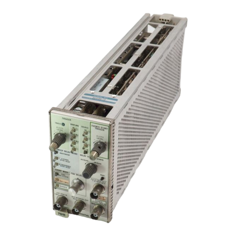
Tektronix 321 A User manual

INSTRUCTIC>N
MANUAL
TYPE
321A
OSCILLOSCOPE
T
ek
tronix, Inc.
S.
W.
Millikan
Way
• P. 0 .
Bo
x
500
• B
eaver
t
on
,
Or
e
gon
97005
•
Phone
64
4-0
1
61
e
Cab
l
es
: Tektronix
070
-
425
564
AU
Tektto.
i*lt!iflijilllllib
GQGinst
defective .
••
._,.
ship for
one
year.
·.
Any
que
stions with respect to the wor-
raaty mentioned
above
should
be
token up
with your Tektronix Field Engineer.
Tektronix repoir
and
replacement-port
semce
is
geared
directly to the field,
there
-
fore
all requests
for
repairs
and
reploce-
JIIent ports. should
be
directed to
the
Te
k-
tfonix Field Offic:e oc Representa
ti
ve in your
area
.
Th
is
procedure will assure you the
fclstett
po
ssible servic6. Please
inctude
th_e
iftsttument Type
and
Serial number with all
....,ests
for ports or service.
• Specifications
and
pr
ice
change
priv-
""-'
reserved.
.,. :Copyright © 1964 by
Tektroni
~,
Inc
.,
.
~erton,
Oregc)n. Printed
in
the United
.,.
'$ililes of America.
All
rights reserved.
Oottents
of th
is
publication may n
ot
be
re-
..
~uced
in
o
n~
form without permission
he copyright owner.
Type
321A
Type
321A
SECTION I
CHARACTERISTICS
lntrodudion
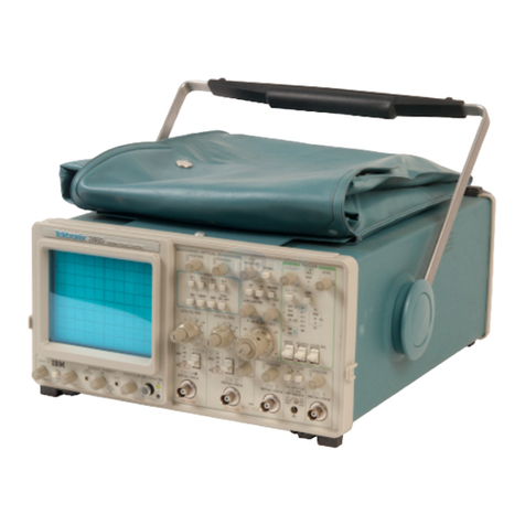
The Tektronix Type 321A
is
a high-performance,
dc
-to-6
me, transistorized oscilloscope. Its light weight, small size
and
ability to
operate
from o variety
of
powe
r sources
make
it a versatile field
and
laboratory instrument. The oscillo-
scope
con
operate
from its internally-contai
ned
rechargeable
battery
pock, on external
de
source
or
from o 115/230-vo
lt
50-800 cycle
ac
line. Regulated
power
supplies
in
the
instru-
ment, accur
ate
calibration,
and
precise linearity assure
exa
ct
time
and
amplitude measurements despite normal voltage-
source
and
powe
r-
supply-lo
ad
changes
that
occur under
odual
operating
conditions.
Operating
temperature
range
derived from tests
in
dicates
optimum performance
and
reliability on its self-
conta
i
ned
batteries from
o·
to + 40° c
ot
altitudes up to 15,000 feet.
Temperature
range
without batteries when
opera
ting from
on
external source
is
-
15
• C to
+55
• C. Non-operating tem-
perature
range
is
-55"
C to
+7
5"
C without
batteries
and
-40•
C to +
60"
C with batteries
at
alt
itu
des
to
50
,
000
feet.
For
the
operator's
convenience, a front-panel
battery
lighl
in
dicates when the internal batteries o
re
low.
If
external
de
or
ac
operation
is
being
used instead
of
the batteries,
the
light turns on
if
the external volt
ag
e source
drops
too
low
for
proper
power
supply regulation.
A 4-position
power
switch on the front panel permits
convenient selection
of
charging
rote
and
/or
power
source.
Vertical Deflection
System
Bandpass-De to
at
least 6 me (3-db down) using
de
cou-
pl
in
g; using
oc
coupling, low-frequency
3-db
down
po
in
l
is 2cps typical from a 1-kc reference.
Sensitivity-0.01
v/div
to 20
v/div
in
11
calibrated
steps;
occurocy is within
3"/o
of
front-
pane
l markings. Con-
tinuously variable from 0.
01
v/div
to
abou
t
50
v/div
uncolibroted.
Input lmpedanc
e-35
pf nominal
paralleled
by 1
megohm
(:.t 1
"/o),
8.2
pf nominal paralleled
by
10
megohms
(±2%1
when using the P6006
lO
X Probe.
Maximum Allowable Input Voltage
Roting-600
volts com-
bined
de
and
peak
oc
; 600 volts (not 1200 volt
s)
peak-to-
peak
oc
.
Triggering
Type-Automatic,
or
amplitude-level selecti
on
using
pre
-
set
stability.
Modo-Ac
-c
oupled
or
De-coupled.
Slope-P
lus, from rising slope
of
triggering waveform,
or
minus from negative slope
of
triggering waveform.
Source-Internal from vertical signal,
or
external from
triggering signal.
Signal Requirements-Internal: 0.2
majo
r division vertical
deflection at 1kc increasing
to
1
major
division
at
6 me.
External: 1 volt peok-to-peak
at
l kc increasing to 3 volts
peak
-to-peak
at
6 me. Nominal input impedance: 5 pf
paralle
l
ed
by
100 kilohms (± 20%).
Sweep
Type-Miller Integrator.
Sweep
Rotes-0
.5JLsec/div
to
O.S sei:/div in 19 c
alibrated
steps. Accurate
5X
sweep
magnifier extends calibrat
ed
range
to
0.1
p.sec/div.
Calibrated
sweep-rote accuracy
is :
t:
3"/o.
Sweep time adjustable between steps
and
to
~
1.5
sec/div
uncolibrated.
External
Ho
rizontal Input
Bandpas
s-
De
to
at
least 1 me (3-db down).
Deflection
Foetor-!
vfdv
+
10"/o
with 5X magnifier
an
.
Input
lmpedanc&-30
pf
typical paralleled by 100 kilohms
1±
5%
).
Amplitude Calibrator
Square
Wove-Frequency
about
2
kc.
Amplitud
e-500
mv
peak
-
to
-pe
ak
. Also
40
mv peok-to·
peak
internally coupled in CAL4
DIV
position
of
VOLTS/
DIV
switch. Peak-to-
peok
amplitude accu
racy
is
±
3%
.
Cathode-Ray Tube
Typ
e-Speci
al Tektronix-manufactured 13211.
3"
flat-face,
post-deflection
acce
le
rator
. l
ow
healer
power
.
Accelerating
Potcntiol-4
kv.
Z-Axis Modulation-External terminal permits
RC
coupling
to
crt grid.
Unb
lonking
-Defle
ction unblanking.
Phosphor-Type
P31
normally furnished; PI,
P2
, P7,
and
Pl
l phosphors optional.
Other
phosphors furnished on
special
order
.
Graticule
Illumination-Variable
edge
lighting
when
operating
from
ac
line.
Display
Area
-Marked
In
6-vertical
and
10-horizontol 1
/4"
divisions.
Power Requirements
Source-Operates
from I0 size D flashlight cells,
or
10
size D
rechargeable
cells (approximately 3 hours using
2.5
ampere
-hour cells; approximately 5 hours using 4
1-1
Choraderistics -
Typ
e 321A
ampere-hour cells),
or
11.5
to
35 volts
de
(aircraft,
auto
,
boot, etc.),
or
103.5 to 126.5 volts or 207 to 253 volts,
rms,
50
to
800 cycles, single-phose oc.
Power Consumption-Approximately 700
mo
from
internal
batteries
or
eldernol
de
source; 20 watts nominal at
115
-v
olt
ac
line.
Temperalure Prot
ection-
Thermal cutout switch interrupts
power
if
amb
ient temperature exceeds
13
1"
F (55"
C).
Built-
in battery charger
is
standard equipment.
Environmental
Capabilities
Vibration
(operating)-0.025"
peak-to-peale, 10 to 55 to
10 cps in 1 minute sweeps (4. G's) for 15 minutes
on
each
axis..
Three-minute vibration
at
resonance or
55cps on each axis.
Shock (operot
ing}-20
G's,
lj
2 sine, 11-msec duration.
1-2
Two shocks each direction along each
of
the
three
ma jor a
xis:
bollom, lop, left side, right side, front
and rear.
To
t
al
of 12 shocks.
Shock lnon-operaling)-60 G's,
1f
2 sine,
11
-msec duro-
lion.
One
shock each direction al
ong
e
ach
of the three
major axis; total of 6 shocks.
Hum
idity (non-o
perating)-Mee
ts
Mi
i-
Std-2028, method
106A
(ex
cept
freezing
and
vibrat
ion)
through 5 cycles
(120
ho
urs).
Transit (non-
ope
roting}-Meets Notional Sofe Transit lest
when factory
packaged
. Vibration for
one
hour
at
slightly greater than
one
G.
Eight
een-inch
drop
in
any
orientation.
Mechanical Spe(ificotions
Construct
ion-A
luminum alloy chassis
and
cabinet.
Finish
-Anodized panel, blue vinyl-finish cabine
t.
Dimensions-Slf,"
high, 53//' wide, 16"
deep
overall.
ACCESSORIES
Information on accessories
fo
r use with this instrument
is
included at the r
ear
of the mechanical ports list.
SECTION 2
PRELIMINARY
INSTRUCTIONS
Power Requirements
The
regulated power supplies in the Type
321
A w
ill
operote
form 115-v or
23
0-v
rms
oc line, from
on
external de
so
urce
(11.5 to 35 volts),
or
from o ''battery pock
''
consisting
of
either
10
size D flashlight cells
or
10 size D recharge
ab
le
cells.
Fuse
Data
Use
only the recommended f
uses
in the Type 321A Oscil-
loscope. The upper
fu
se
, F
621
(
se
e
Fig.
2-1
),
is
a 1.5-amp
3AG
Fast-Blo;
th
e
lower
fuse
,
F601
,
is
a .
25
-omp
3AG
Fast
-
Bio.
Neither
fuse
needs to be changed
if
the oscilloscope
is converted from one line voltage to the other
(115
v and
230v).
fig
. 2- 1.
location
of
fu
ns
and
Charger
twitch
lleft-sl
de
v
ie
w) .
Ac
Operation
Unless togged otherwise, your instrument
is
connected
ot
the factory
lor
operation
ot
103
.5
to
126
.5 volts, 50 to 800
cycles oc (
11
5 volts nominal).
How
ev
er, provisions ore mode
for easy conversion to operate at 207 to
253
volts,
50
to
800
cycles
(230
volts nominal).
The
power
transformer
T601
is
provided with split input windings which ore normally
connected in parallel for 115-volt operation, but which can
be connected in
series
for
230
-vo
lt
operation.
The
primary windings ore marked
l,
2,
3, and 4. Terminols
1 and 3 ore connected to one winding and terminals 2 and 4
ore
connected to the second winding. The oc inp
ut
leads ore
connected to terminals 1 and 4 for both 115-volt one 230-
®
volt
operation,
so
these connections
do
not hove to be
chang
ed
when converting from one line voltage
to
the other.
When wired for 115-volt operation, te
rm
inals 1 and 2
are
joined
by
o bare
bus
wire, ond termina
ls
3 and 4 ore simi-
larly
joined, as shown in Fig. 2-2
1o).
To convert to 230-
volt
operation, remove the bore bus wires between these
termina
ls
and substitute a single connecting
wire
between
terminals 2 and 3,
as
shown in Fig. 2-2(b).
To
turn on the Type 321A when the power cord is con-
nected to the oscilloscope power connect
or
and to t
he
oc
voltage
so
urce,
se
t the POWER switch to
EXT
ON.
To turn
off
the oscilloscope,
set
the POWER switch .to
TR
IC
KLE
.
The
TRICKLE
position con be regarded
as
the normal "
off
" posi-
tion for t
he
instrument.
To
115
-v AC
(al
To
230-v
AC
F
lg
.
2-2
. (
al
Transform
er
connection
for
operation
from 1
03
.5-
126
.5
vo
lt
oc
line
;
lb)
tonneclions
fo
r
operation
from
207-253
volt
ac
line
.
As
lo
ng
as
the oc power cord
is
connected to the oc line,
power
is
being applied to the
power
transformer T
60
1, ac-
rectifier c
ir
cuit, and groticule
light
s for
oil
positions
of
the
POWER switch.
Appli
cation
of
power to these circuit
is
re-
quired to provide battery-charger operation for
th
e internal
batteries; t
he
groticule lights provide visual indication that
these
circuits ore ··on". Power to the battery charger itself
is
controlled by o Charger switch
(see
Fig. 2·1). If the switch
2-1
Preliminary Instruction
s-
Type 321 A
1s
set
to LOW or HIGH, the ac rectifier
is
connected to the
battery charger circuit which, in turn, provides charging cur-
rent to the internal rechargeable batteries.
NOTE
If
dry
cells
ore
used inst
ead
of
rechargeable
bat-
teries, then
the
Charger
switch must be set
to
DR
Y
CELLS
to
disconnect
the
charger
circuit. For
further
information
about
battery
operation,
r
efer
to
the
topics
tilled
"Battery
Operation"
and
"Ba
tt
ery
Charger"
appearing
in this sect
io
n
of
the
manual.
If
the
Type
321
A
is
being operated exclusively from the
oc line and the internal batteries ore removed, the Charger
switch
can
remain
in
the
DRY
CELLS
position
to
disconnect
the charger
ci
rcuit.
If
you prefer
to
completely turn
off
oil power to t
he
Type
321
A, set the
POWER
sw
itch
to
TRICKlE and either disconnect the power cord from the
ac li
ne
or turn
off
the power
at
o wall switch (or equiv-
alent).
Batt
ery
Operation
Operation from the internal battery
source
can be accom-
plished by
using
:
1.
Ten
size D flashlight cells (approximately 1
/1-hour con-
tinuous operation, more with intermittent operation),
or
2.
Ten
si
ze
D Alkaline cells
such
as Eveready
E95
,
Bu
rgess
Al-2, or Mallory MN-1300 (about 21
/2 hours
co
ntinuous
operation), or
3.
Ten size D ni
ckel
-cadmium rechargeable cells (up to
about 5 hours continuous operation, depending on the
type
used).
The
nickel-cadmium cells ore the
most
practical type where
considerable battery operation
is
planned.
To
install the cells, ftrst open the battery cover
as
ill
us
-
trated
in
Fig. 2-3. Next, install the batteries by following
the procedure gi
ven
in
Fig
.
2-4.
CA
U
TIO
N
Be
su
re
to
observe
cell
po
lari
ty i
ndi
cated on
the
battery
cover.
To
turn on
the
Type 321A when operating from the internal
batteries,
set
the POWERswitch
to
BATT
ON.
To
turn
off
the
oscilloscope,
set
the POWER switch
to
one
of
the
OFF
posi-
tions-FULL or
TRICKLE.
These
OFF
positi
ons
disconnect
t
he
batteries
from
the
oscilloscope load
(1
0-volt regulated
supply)
so
there
is
no battery drain.
To
charge the recharge-
able batteries, refer
to
the next topic titled "Battery Charger".
Fig.
2·3
• .Removing
lhe
ba
ii••Y
cover
from
the
Typ•
321
A
Oscllloltope
.
2-2
Preliminary
Instructions-
Type 321 A
Fig.
2-4
. Proced11re for
ln
stolllng
the
bo
»eries
.
Battery Charger
As mentioned previously, the
battery
charger
is
connected
to
the
internal batteries
as
long
as
the
oc
power
cord
is
connected to
an
ac
power
source
and
the
Charger
switch
(see Fig.
2-1)
is
set
to
HIGH
or
LOW.
No
charging occurs
if
the
Charger
switch
is
set to
DRY
CELLS
.
Table
2-1
summarizes the charging currents that
con
be
obtained
by
using various line
voltages
in
combination with
various settings
of
the POWER
and
Charger
switches.
Th
e
table
shows the Type 321A wired for 115-volt nominal line
operation.
If
the
oscillosco
pe
is
wired for 230-vo
lt
nominal
line
operation,
the charging currents will still
be
the
some
but the
ac
li
ne
voltages
will
be
twice
the
amount
shown in
the table.
Use Table 2-1
as
on
aid
in
determining the
proper
posi·
lion for
the
POWER
and
Charger
switches for the particular
brand
or
type
of
rechargeable
batteries being used
in
the
Type 321A. After setting the switches to th
eir
proper
posi-
tion, the line
voltage
con
then
be
set to the charging
rote
recommended by the manufacturer
of
the cells. An
auto-
transformer having a rating
of
at
least I
ampere
and
equ
i
pped
with
on
rms-reoding
oc
voltmeter
con
be
used
to
set the line voltage.
When
using
rechargeable
batteries, sixteen hours
of
charg
ing
at
the full
rated
charging current
recommended
by the manufacturers should
be
adequate
to fully
charge
the batteries. Excess charging
may
damage
the
batter
ies.
One
method for determining
charge
conditions
of
the
bat
-
teries
is
to
set the POWER switch to BAIT
ON
and
then
measure the
voltage
across the
battery
terminals (
sec
Fig.
2-
4)
. A
read
ing higher than 13 volts
in
dicates that the
ba
tteries
are
fully
charged.
A
reading
lower than
13
volts
indic
ates
that more
cha
rging time
is
required.
As mentioned previously,
if
dry cells
ore
installed
in
the
battery
holder
and
the
Type 321A
is
being
operated
from
the
ac
line, the
Charger
switch must
be
set to the
DRY
CELLS
position. This position disconnects the charging circuit from
the batteries.
TABLE
2-1
Charging Currents
PO
WER •
Charger
Aproximote
Charging
Swit
ch
Switch
Current
in
Ma
Position
Po
sitio!:'...
]_0~.5
-
"
...
)
-
~(~~
;~
(~
.-
~
·.·.
;:,
12
~
~
1
126.5
v
-
Low
······
·
2o
·
··········
2:.~
··r-·
v
31
· 33
EXT
ON
- -
..
······----·-··--
--
·
--
--
·
·-
·-
· -
[6~
r----·
;f.
-
;:
'
--1§
--·-
~~
L
-
---·---
!~
····-
TRICKLE
- - ··
-········-
-
HIGH 34
37
1
41
4A
48
~~~
-~
~~~
---
·.·.·.·
..
-~
J
-
~
~-
-:
r
;~
-=-
~~
- --
-
·---·-
~~
~
"The BATl
ON
po•llion
is
not
Inclu
ded
in
the
tab
le
becouae
the
T
ype
321 A
should
not
be
operored
from
the
oc
tine
ond
lho
bollories or
the
some
limo. R
eosona
Bollory
drain
oxc::eod•
chorg
·
lng
role
.
2-3
Prelim
inary
Instructions-
Typ
e 321A
De
Operation
Operation from on external de
source
is
ocompli1hed
by
connecting
the
special pigtail-type de power cord in the
proper manner.
Fo
r
11.5
-
to
20-volt operation, t
he
block
1+1
and white 1-) leads ore connected to the voltage
source
; for
20-
to
35
-volr operation, the green
1+1
and
wh
ite
1-·)
lea
ds
or
e connected
to
1hc
voltage source. When the
connect
io
ns
to the external de voltage
source
arc properly
mode, the external de source
is
floating with
res
pect to the
Type
321A
chassis.
Up
to
600
volts difference is permissi-
ble,
if
necessary.
To
turn on the Type
321
A,
set
the
POWER
swi
t
ch
to E
XT
ON
.
To
turn
off
the oscilloscope,
set
th
e
POWER
switch
to
one
of
t
he
OFF
pos
itio
ns
-
TRICKLE
or
FULL.
When operating from
the
external de source,
the
ac line
cord
shou
ld be disconnected.
Tha
t is, only one
of
th
e exter-
nal
sources
sh
ould be
used
rather than bo
th
at
the some time.
2-4
NO
TE
Th
e
internal
battery
cha
r
ge
r circuit is d
is
connected
during
external
de
operation
. Ther
efo
re, ext
ernal
batteri
es
(
if
used as
the
de sourcel
cannot
be
ch
arged
by
connecting
the
line
cord to
the
oc
line.
Also, on external de source
cannot
be
used
to
ch
ar
ge
the
internal
batter
i
es
since the POWER
switch does
not
electrically
connect the
twa
sources t
ogether.
LOW
BATTERIES
Ught
The
LOW
BATT
ERI
ES
light
tu
rns
on when the following
conditions exist:
1.
Tho
POWER
switch
is
set
to
BA
TI
ON
and the internal
batteries drop to
11.5
v (
:!.:.
0.2
v)
or
lower.
2.
T
he
POWER
swi
t
ch
is
set
to
EXT
ON
and the external
source
voltage
is
low
enough to ca
use
the Type
321A
un-
regulated voltage to
drop
to about
11.5
v
or
lower.
SECTION
3
OPERATING INSTRUCTIONS
General Information
The Type 321A Oscilloscope
is
an
extremely versatile in-
strument,
ad
aptable to a great number
of
app
li
cations.
How
-
ever, to make full
use
of
the instrument,
it
is
neces
.sary that·
you understand completely the operation
of
eoch front-panel
control. This portion
of
the manual is intended to provide
you with the basic information you require.
If
you
ore
familiar with other Tektron
ix
oscilloscopes, you should
have
very
litt
le difficulty in understanding the operation
of
the
Type
321
A.
The
function
of
many controls is the same as
the function
of
corr~sponding
controls on other Tektronix
instruments. A front-panel view
of
the Type
321
A
is
shown
in Fig. 3-1.
Intensity Control
The
INTENSITY control
is
used
to adjust the trace bright-
ness.
This permits adjustment
of
trace in
tens
ity
to suit the
ambient
light
conditions and changes in intensity caused
by
changes in the sweep triggering rote (sweep
duty
cycle).
Clockwise rotation increases the intensity and counterclock-·
w
ise
rotation decreases t
he
intensity.
Focu
s and Astigmatism Controls
The
FOCUS and ASTIGMATISM controls operate in con-
junction
with
each
other to allow you to obtoin o sharp.
clearly defined spot
or
trace.
To
odiust
these
controls:
1. Adjust the
IN
T
ENSITY
control for the most pleasing level.
2.
Set
the ASTIGMATISM control
to
midscale.
3.
Adiust the FOCUS control for sharpest detail.
4.
Adjust the ASTIGMATISM control
as
necessary for best
overall focus.
Groticule Illumination Control
The
graticule
used
with the Type
321
A
is
accurately
marked with 10 horizontal and 6 vertical divisions, with 0.2-
division markers on the centerlines.
These
groticule markings
allow
you to obtain time and voltage measurements from
the oscilloscope screen.
Graticule illumination
is
adjusted
by
the
SCALE
ILLUM
control, located just to the right
of
the oscilloscope screen.
Rota
ting the control clockwise increases the brightness
of
the
graticule markings and counterclockwise rotation decreases.
the brightness.
NOTE
The
gratic
ule
is
I
llu
mina
ted
only
when
ope
ra
ting
from
on
oc
line
. This permits
longer
oper
at
ion
when
on
batter
ies.
Positioning Controls
Two controls are
used
with
the Type
321
A Oscilloscope
to
position the trace or spot
on
the screen.
The
HORIZONTAL
PO
SITION control moves t
he
trace
to
the right when
it
is
rotated clockwise and to the left when
it
is
rotated counterclockwise. This control
has
o positioning
range
of
approximately
15
divisions with the sweep magnifier
off, ond approximately
75
divisions with the sweep magnifier
on.
The
HORIZONTAL POSITION control
is
a combination
coarse/vernier type
of
control. Built-in blaclda
sh
between
its
two
sections permits
30°
of
vernier adjustment for o given
coarse setting.
IF
a
30°
range
is
exceeded, the coarse ad-
justment tokes over to provide fast positioning
of
the trace.
The
VERTIC
AL POSITION control has sufficient range to
position the trace completely
off
the
top
or bottom
of
the
screen,
or
to
any
intermediate point. The trace moves up
when the control
is
rotated clockwise and
down
with the
counterclockwise rotation.
Inten
si
ty Modulation
The crt display
of
the Type
321
A Oscilloscope con be in-
tensity modulated
by
on external signal to display additional
information. This
is
accomplished
by
disconnecting the
grounding
bar
from the
CRT
GRID connector
at
the rear
of
the instrument and connecting the external signal to this
terminal. A negative signal
of
approximately
30
volts peak
is
required to cut
off
t
he
beam from maximum intensity,
less
with lower intensity levels.
Negat
ive-going signals as
low
as
5 volts peak
will
accomplish intensity modulation.
HORIZONTAl
DEFLECTION
SYSTEM
Horizontal Sweep
The
usual oscilloscope display
is
a graphical presentation
of
instantaneous voltage versus time. Voltage
is
represented
by
vertical deflection
of
the trace and time
is
represented
by
horizontal deflection. To obtain o useful display, the spot
formed
by
the electron beam
is
deflected horizontally at a
known rote,
so
that any horizontal distance on the
screen
represents a definite known period
of
time.
The
trace formed
by
the deflection
of
the spot across the screen
is
known
as
the horizontal sweep. Since the horizontal
def
lection
of
the
spot bears o definite relationship to ti
me
,
and
provides the
means for making ti
me
measurements from the screen, the
horizontal sweep
is
also known
as
the time bose.
(See
Fig.
3-2).
The
rote
at
which t
ho
spot
is
deflected across the screen
is
accurately controlled
by
the setting
of
t
he
TIME/DIV con-
trol.
Tho
setting
of
the TIME/DIY control determines the
sweep rote, and
thus
the number
of
cycles displayed
on
the
crt
screen
.
The
control
is
set to display the portion
of
the
waveform you wish
to
observe.
3-1
Operating lnstrudl
ons
-Type 321A
CRT
CONTROLS
FOCUS
-Controls
aharpneu
of
spot
or
trace
.
ASTIGMATISM-·lhed
In conjunc•
li
on
with FOCUS to
obta
in
overa
ll
focus.
VERTICAL CONTROLS
VERTICAL
POSITI
ON
tra
ce vertically.
AC-OC
-
GND-Sele
cls
tither
AC
or
--
-+~•
.J
OC
In
put
coupling.
Th
o GND
posl·
tion
connectt
the Vertic
al
Amplifi
er
to
ground
b111
does
not
gro
un
d
the i
nput
sig
rta
l.
90LTS
/D
IV
a nd VARIABlE -Se-
le
ct
s vertical defle<lion fa<lor
and
cali
brato
r
signa
l.
INPUT -Terminal
for
accepting
w
avefo
rms
to
be
disp
laye
d
on
crt.
CAL
OUT
500
MY-Term
i
nal
pro-
vides
500
-mv sq11are
wave
for
com
pe
ns
ating
probe
.
DC
BAL-I'otent
l
ometer
for
se
tting
de
balance
of Vertical Amplifier.
INTENSITY-Cont
ro
ls
brigh
tneu
of
trace
.
SCAlE
llLUM--Adjuate
br
lgh
tneu
of gratfcule
marking
s !
when
oper-
at
ing from AC Hnel .
HORIZONTAL
POSITION--Coars
e-
vernier
type
of
control
that
posf·
lions
t
race
ho
rlaon
ta
lly.
POWER
-Switch
tum
a
regula
t
ed
10
-~
olt
power
on
and
off
.
Al
so,
selects
charging
rate
.
EXT
HORIZ IN
PUT
-Terminal
for
accepting
ex
ternal
horizontal
sig-
nal.
CONTROLS
S
LOPE--Oe
ter
min
es
whether
sweep
is
tri
ggered
on
+ or - sl
ope
of
trig
ge
ring
signa l.
AC-OC-Sel
e
ds
AC
or
DC
coupling
for tri
gger
ing si
gna
l.
STA
8tl
tT
Y-Potentlo
met
er
for
s
et
·
ling
de
level
of
swee
p genef'Citor.
INPUT- Term
inal
for
ac
ce
pting
ex-
t
erna
l t
riggering
signal.
Fig. 3-1.
fun
cti
on
s
of
the
Type
321
A Oscilloscope
fron
t
-pane
l c
ontro
ls.
3-2
l
I-
f-
1
.--
1
.--
J
rP
...
w w
r r
V
oltage
~
f-1
f-1
Time
--------..
Fig.
3-
2. T
he
o sd
llo
~e
ope
plots Inst
an
tan
eous voltoge v
ert
us t
ime
,
thereby
se
rvi
ng
bo
th as o voltmet
er
o
nd
a timer.
The
Time
Ba~e
has
19
accurately calibrated sweep
rate
s
ranging from
.5
JJ.Sec/div
to
.5
sec/div.
These
calibrated
sweep ra
tes
ore obtained when
the
VA
R
IA
B
LE
(TIME/DIY)
con
trol
is
fully clockwise in the CA
LI
S position.
The
TIME/
DIY switch selects t
he
calibrated
swee
p rates and can be
rotated 360 •
since
there are no mechanical stops.
The
VA
RI
·
ABLE
control permits you to
vary
the
sweep rote continuously
between
.5
11-S
ec/div
and
approximately 1.5 sec/div.
All
sweep rates obtained with the VA
RIABLE
control in
any
position other than fully clockwise ore uncalibroted.
Swe
ep Magnifier
The
swee
p magnifier allows you to expand
any
two
·
division portion
of
the displayed waveform
to
the full ten·
division width
of
the grolicule.
This
is
accomplished by first
us
ing the HORIZONT
AL
POS
ITI
ON control to move the
par·
lion
of
the display you wish
to
expand to the center
of
the
graticule, then placing
the
5X
MAG
switch in the ··on" posi-
tion (pull out the red
VARIABLE
TIME/DIY knob;
see
Fig.
3-3).
Any portion
of
the display magnified by
the
horizontal
sweep con then be observed by rotating the
HORIZONTAl
POSITION control.
In
magnified sweep operation, the sweep rote
in
dicated
by
the position
of
the TIME/DIY switch
must
be
div
ided
by
5 to obtain the actual ti
me
required for
the
spot to move
one division.
For
example, if the
TIME
/DIY switch
is
set
to
5 MILLI
SEC,
the actual time per division is 5 milliseconds
divided by 5,
or
1
mi
lli
second per
div
is
io
n.
The
actual time-
per-division
mus
t be used for all time measurements.
External Horizontal Input
For special applications you
can
deflect the trace hori-
zontally with
some
externa
lly
derived waveform rather than
by means
of
the internal sweep sawtooth. This allows you
to
use
the oscilloscope to
plo
t one function versus another.
To
use
the
external horizontal input, connect the externally
derived waveform to the
EXT
HORIZ INPUT connector
and
place the TIME/DIY switch in the
EXT
position.
The
hori-
zontal deflection foetor
is
approximately 1 volt
/di
vision
with
the 5X
MAG
on.
Op
er
ating
In
struction
s-
Type 321A
TtME
I
OIV
SX
MAG
OFf
SX
MAG
ON
lpultl
Unmag
nified WoYefarm
rr
.
..
. I l .,
...
·.·
!:-_
•
b.
.::t-
r::
f=
jY I
''T
~
·t.-rl
1-;--
rr"
·
1
~
..
t-
i- "
lr
.....
t::-
L_L_
/ \
I \
/ I \
/ ' \
r-
rl
...
.....
..
.. -
r-
l-
r-
1'
-
..
...
···
~
·1-
t::
..
-++
++~~
~
....
.
-l
..l
~-
r-
-
~·
=Fi::t
-H~
:Ft-~
~ ~
....
-
......
·-'-J.......L...J
Magnified WaYefMm
Fig. 3·
3.
Operotlon
of
the
s
weep
magnifier
.
Sweep
Triggeri
ng
T
he
oscilloscope display
is
formed by the repetitive sweep
of
the spot across the oscilloscope screen.
If
the sweeps
ore
allowed
to
occur
at
random,
or
a rote unrelated
to
the input
waveform, t
he
di
sp
layed waveform
will
be !raced out
at
a
different point on the screen with each sweep. This will
either ca
use
the waveform to drift across the screen
or
to
be
indistinguisha
ble
.
In
most
ca
s
es
it
is
desirable for repetitive waveforms
to
appear
st
ationary on the oscilloscope screen
so
that the
characteristi
cs
of
the waveform
can
be examined in delail.
As
a
necessa
ry condition for this type
of
display, the
st
art
of
the sweep must bear a definite, fixed-time relationship to
the observed waveform.
This
means that each sweep
must
start
at
the
some
time, relative
to
some point on lhe observed
waveform.
In
t
he
Type
321
A,
this
is
accomplished by start-
ing
or
triggering the sweep with the displayed waveform, or
with another waveform bearing o definite time relationship
to
the
displayed waveform.
The
wav
ef
orm
used
to
start the horizonlal sweep is called
a "triggering signa
l''
(whether
it
is lhe waveform being ob-
served,
or
some
other
wa
vefo
rm)
.
The
following instructio
ns
tell
you
how to select the triggering signal source.
Selecting the Triggering Source
In preparing the Type
321
A Oscilloscope for triggered
operation
of
t
he
sweep, it
is
first necessary to
se
lect lhe
triggeri
ng
signal source which
will
provide
the
best display
fo
r the particu
lar
application.
The
sweep con be triggered
by the displayed waveform,
or
by on externally derived
waveform.
This
selection is mode
by
the setting
of
the
IN
T.
EXT
switch
(see
Fig.
3-4).
Each
type of tr
ig
ger
ing
has
certain
advantages for
some
app
lications.
Triggering fr
om
the displayed waveform
is
the melhod
mosl common
ly
used. T
he
displayed waveform
is
selected
when the tNT-
EXT
switch
is
in the INT position. Internal trig-
3-3
Operating
In
structions -
Typ
e 321 A
gering is convenient since no external triggering connections
ore
required. Satisfactory results
ore
obtained
in
most appli-
ca
tions.
To
trigger the
sweep
from
some
elCternal waveform, con-
nect the triggering waveform to the !TRIGGERING)
INPUT
connedor
and
place
the
!NT-EXT
switch
in
the
EXT
position.
!External triggering provides definite
advantages
over
in-
ternal tri
gger
iog
in
certain cases.) With external triggering,
the
triggering signal usually remains constant
in
amplitude
and
shape.
It
is
thereby possible to observe
the
shaping
and
amplification
of
o signal
in
on
external circuit without reset-
ting the oscilloscope triggering controls for
each
observation.
Also, time
and
phose relationships betvtccn the waveforms
at
different points in the circuit
can
be
seen.
If,
for
example
,
the external triggering signal
is
derived
from
the waveform
at
the input to o circuit, the time relationship
and
phose
of
the
wa
veforms
at
each
point
in
the circuit
ore
compared
to
the input signal by the display presented
on
the oscilloscope
screen.
Selecting the Triggering Slope
T
he
horizontal
sweep
con
be t
riggered
on
either
the rising
or
falling portion
of
the triggering waveform.
When
the
SLOPE
switch
is
in
the + position, the
sweep
is
triggered
on
the rising portion
of
the
triggenng
waveform; when
the
Displayed
Wa
veform
-
'---
"----
tNT
SLOPE
switch
is
in
the -position, the
sweep
is
tri
ggered
on
the fatting portion
of
the waveform (see Fig. 3-5).
In
many applications the triggering
slope
is
not
im
portant
since triggering
on
either
slope
witt provide o display .suitable
to
the application.
Selecting
the
Triggering Mode
Aut
omatic
Mode
Automatic triggering
is
obtained
by rotating the
(TRIG-
GERING!
LEVEL
control fully counterclockwise to the AUTO
position.
This
mode
allows triggering
ot
t
he
average
voltage
point
of
the
applied
waveform. Also, the
sweep
runs
at
approxi
-
mately a 50-cycle rote when
no
triggering signals
ore
Op·
plied; this produc
es
a reference tr
ace
or
baseline
on
the
screen. Automatic triggering con
be
used with both internal
and
external triggering signals, but for most waveforms
tt
is
useful
only
for triggering
at
frequencies
above
50 cycles.
Automatic triggering saves considerable time
in
observing
a series
of
waveforms since
it
is
not
necessary to reset t
he
triggering level for
each
observation. For this reason
it
is
the mode
that
is
normally used.
Other
modes
ore
gen
erally
used only f
or
spec
i
al
app
lic
ations,
or
where
stable
trigger-
in
g
is
not
attai
nab
le
in
the
automatic
mode.
Extem
al Trigger
ing
Waveform
E
X
T------------~
I
NT-EXT
Switch
INP
UT
Os<llloscope
Sw.ep·Starting
C
ircyih
Fig.
3-4
The
triggering
sillr>af Is
selected
from
two
pon
i
ble
soYrcet with
the
INT-EXT
switch.
3-4
SL
OPE
Swee
p T
tlggers
On -
Slope
SLOPE
Sweep
Tt
lggeu
On
,_
Slope
Op
era
ting
In
stru
ct
ions -Type 321A
L\ (
~
L \
1
~
\
j_
l 1
ll 1 J v
J
i
l I
~.I
Wa
vefot
ml
obtained
with
t
he
tr
ig-
gering
level
control
se
t In
the
- r
egion.
~
! l\
~
.1ll
~
1\
\
J '
.I
v 1 1 /
~
r l\
\
'
~
\ I
\ j
~
L 1\ v
I _\ v
1\
If '
,J
~
1
L
..
~
lL
Wav
eforms
obtain
ed
with
t
he
trig-
ger
i
ng
le
vol
con
trol
set
In the
+
region.
( \
r'
IJ
\ l
I
~
' 1 \
~
..
/'
\
.\
\
J
~)
r
I.
~
~
F
ig.
3-5
. Effects
on
the
osdlloscope
display
produced
by
+
ond
-
uHings
of
the
SlOPE
and
LEVEL
controls
.
3-5
Operating
Instructions
- Type 321 A
Ac
Mode
Ac-mode triggering
is
obtained
by setting
the
AC-DC
switch
to
the
AC
position. This
mode
provides
stable
trig-
gering
on
virtually all types
of
waveforms. As o
general
rule, however,
the
oc
mode
is
unsatisfactory for triggering
with low
amplitude
waveforms
at
frequencies
below
approxi-
mately
15
cycles. This fi
gure
will
vary
depending
upon
the
amplitude
and
shape
of
the triggering waveform
and
should
not
therefore
be
set
as
on
absolute
standard
.
Tr
igge
ring
a~
frequenc.it?s
below
15
cycles con
be
accomplished
when
hi
gher
amplitude triggering signals
ore
used
.
In
the
oc
mode,
the
triggering point
depends
on
the
overage
voltage
level
of
the
triggering signals.
If
the
tr
ig-
gering
signals occur or
random,
the
average
voltage
level
will vary causing
the
triggering point
to
vary
also
. This shift
of
t
he
triggering point
moy
be
enough
so
that
it
is
im
poss
ib
le
to
maintain o
stable
display.
In
such cases you should
use
the
de
mode,
De
Mode
De
mode
triggering
is
obtained
by selling the AC.DC
switch
to
the
DC position. This
mode
of
triggering
is
par
-
ticularly useful
in
triggering from waveforms which
ore
no~
adop
t
able
to
the
oc
mode
, such
os
random
pulse trains
or
very
low-fre
quency
waveforms. Random pulse trains
pose
o special problem
in
the
oc
mode
since the
random
occur-
rence
of
the
input waveforms
causes
t
he
overage
voltage
level
to
shift. This
in
turn may
cou~e
the
triggering level
to
shift to
on
unstable
po
int. This
prob
l
em
is
no
t encountered!
in
the
de
mode
since
the
triggering point
is
determined
only
by
instantaneous voltages.
In
the
de
mode,
when
the
triggering signal
is
obtained
from
the
Vertical Amplifier, varying
the
VERTICAL
POSITION
control will
change
the tri
gger
ing point. For
th
is
reason
,
you may find it necessary
to
readjust the
LEVEL
control
when
1
you
change
the
vertical position
of
the
trace.
To eliminate
this effect,
you
con
use the
oc
mode
provided
the
triggering
signal
is
otherwise suitable for this
mode
of
operation
. In
the
de
mode, t
he
de
level
of
the
e
xt
ernal triggering signals:
will
also
effect
the
triggering
point
.
Generally,
when
the
triggeri
ng
signal
is
small
compared
to
its
de
level, the oc
mode
should
be
used.
How
to
Set
th
e
Tr
iggering
Level
In
the
oc
and
de
triggeri
ng
modes,
the
LEVEL
control
determines the
voltage
le'lel
on
the triggering wo•teform
at
which the
sweep
is
triggered. Using this control,
the
sweep
c
on
be
continuously triggered
at
any
point
on
t
he
waveform
so lo
ng
as
the
slope
of
the
waveform
is
great
enough
to
provide
stable
triggering.
In
the
de
mode,
the
~weep
cannot
be
triggered with
any
degree
of
stability
ot
the
top
of
o
square
wove
, for
example,
because
t
he
time
that
the
voltage-
remains constant
is
comparatively long.
As
a result, the
sweep
triggers
ot
random
points
along
the
top
of
t
he
square
wove,
produc
i
ng
considerable
trace
jitter.
You
can
use
the
some
metnod
to
set
the
LEVEL
control for
eith
er
t
he
oc
or
de.
mode. After selecting
the
triggering1
slope,
rotate
the
LEVEL
control fully counterclockwi
se
to
the
AU
TO position. Then
rotate
the
LEVEL
control clockwi
se
until
the
sweep
no
l
onger
triggers. Continue
to
rotate
the
control
in
the
clockwise direction until the
sweep
again
trig-
gers
and
o
stable
display is
obtained.
Further rotation
of
the
control
in
the clockwise direction causes
the
sweep
to
trigger
ot
more positive points
on
the
triggering waveform. ln
the
fully clockwi
se
direction
the
trace
will free run (Fig.
3-51
.
FREE-RUNNING
OPERATION
With
the
Type
321
A,
you
con
get
o periodic, free-running
sweep,
inde
pendent
of
any
externa
l triggeri
ng
or
synchroniz-
i
ng
signal,
by
rotating
the
LEVEL
control fully clockwise to
the FR
EE
RUN position. This permits
you
to
observe
t
he
trace
without
on
input signal. This
trace
con then
be
used
to
pos
i·
lion
the
sweep
or
to
e~toblish
o
voltage
reference line. The
difference
between
the
traces
produced
in
the
AUTO position
and
the
FREE
RUN
pos
i
ti
on
is
the
repetition rote. The
repet
i-
tion
rate
in
the
FREE
RUN position
is
dependent
upon
the
setti
ng
of
the
timing switch. The repetition
ro
le
in
the
AUTO
position
is
fixed
ot
approximately
50
cycles. At
the
fester
sweep
roles,
the
trace
in
the AUTO
pos
ition will
appear
to
be
dim.
In
the
FREE
RUN
position
the
trace
intensity remains
essentially constant for all
sweep
rates.
VERTICAL
DEFLECTION
SYSTEM
Input Coupling
Input signals
to
the Vertical Amplifier con
be
eit
he
r
ac
-
or
de
-coupled
by
placing
the
AC·DC.GND switch
in
the
ap
-
propriate
AC
or
DC
position.
De
coupling
appl
i
es
both
the
oc
and
de
components
of
the
input signal
to
the vertical
amp
lifier circuit. This permits measurement
of
the
de
voltage
level
os
well
os
the
amplitude of
the
oc
com
pon
ent
.
It
is
sometimes neither necessary
nor
desirable
to
display
the
de
component,
ho
wever,
ond
in
such
cases
as
coupling should
be
used.
Th
is
is accomplished
by
setting the AC-DC-GND
switch
to
AC.
With
oc
coupling, a
capacitor
is
placed
in
series with
the
input connector to block the
de
component
while allowing
the
oc
component
to
be
displayed.
Placing t
he
AC-DC-GND switch
to
the
GND
position
grounds
the
input circuit
of
the
vertical amplifier
to
provide
o
de
zero
reference.
In
this position
the
switch internally dis.
connects,
but
does
not
ground,
the
applied
sign
al
to
the
input connector. Thus, the
GND
position eliminates
the
usual
need
for externally
ground
i
ng
the
(Vertical Amplifi
er}
INPUT
connec1or
of
the
T
ype
321
A
or
the
probe
tip
to
establish o
ground
reference.
Deflection Factor
The electrical waveform to
be
observed
is
applied
to
the
(Vertical Amplifier) INPUT connector. The waveform
is
then
appl
i
ed
through
the
vertical-
def
lecti
on
system
to
cause
the
spot to
be
def
l
ec
t
ed
vertically lo
trace
out the waveform
on
the
screen of
the
crt. The VOLTS/DIV switch controls
the
vertical
def
lection foetor in
acc
u
rate
ly
calibrated
steps. T
he
VARIABLE
control provides uncalibroted
variable
deflection
fac1ors
between
the fixed steps
of
the
VOLTS/DIV
sw
itch.
The
VAR
IABL
E control
has
360°
rotati
on
range
and
o detent
positi
on
when
t
he
control
is
set
to
CALIB
.
NOTE
To
make
the
defle
c
tion
foetor
equal
to
that
indi
-
cated
by
the
VOL
TS
/
DIV
switch,
set
the
VARIABLE
c
ontrol
to
the
CALIS
detent
position.
De
Balance Adju
stment
The need for adjustment
of
the DC
BAL
control
is
indi-
cated
by
a vertical shift in t
he
position
of
the trace
as
the
VARIABLE
(VOl
TS
/DIV) control
is
rotated.
This
adjustment
should be made as follows:
1.
Set
the AC-DC-GND switch to
GND
.
2.
Set
the oscilloscope controls for a free-running trace.
3.
Rotate the
VARIABLE
(V
OLTS
/DI
V)
control bock and forth,
and
adjust the DC
BA
L control simultaneously until the
trace position
is
no longer affected
by
rotation
of
the
VARIAB
LE
control.
Input Signal Connections
Certain precautions must
be
observed when you are con·
necting the oscilloscope to on input signal source. This is
to
insure that accurate information
is
ob
tained from the
oscilloscope display. This
is
particularly true when you
are
observing
low·
level signals,
or
waveforms containing
high· or extremely low-frequency componen
ts
.
For
applica-
tions where you ore observing
low
-level signals, shielded
cables should be used whenever possible,
with
the shield
connected to the
chassis
of
both the oscilloscope and
th
re
signal source. Unshielded input leads ore generally unsatis-
factory due to their tendency to pick
up
story signals which
produce erroneous oscilloscope displays. Regardless
of
the
type
of
input used, the leads should be kept
as
short os
possible.
Distortion
of
the input waveform may result if:
1. Very low-frequency input signals ore oc-coupled to the
oscilloscope.
2.
High-frequency waveforms ore not properly terminated.
3.
The
input waveform contains high-frequency components
which exceed
th
e bandpass
of
the oscilloscope.
You
must
be
aware
of
the limitations
of
the
ins
trumen
l.
In
analyzing t
he
displayed waveform, you
must
consider
the
lo
ading effect
of
the oscilloscope on the input signal
source.
In
most
cases
this loading effect
is
negli
gib
le;
how
-
ever, in
some
applications loading caused
by
the oscilloscope
may materi
ally
alter the results obtained.
In
such
c
ases
you
may wish to reduce the amount
of
load
ing to a negligi
ble
amount through t
he
use
of
o probe.
Use
of
Probes
Occasionally connecting the input
of
an oscilloscope
to
a s
ig
nal source
lo
ods the source sufficiently to adversely
affect
bo
th the operation
of
the source and the waveform
displayed
on
the oscilloscope. In
such
cases
an altenuotor
Op
erating Instructions - Type 321A
probe
may
be
used
to decrease both the c
apa
citive a
nd
res
is-
tive
load
ing caused
by
the oscilloscope to a negligible value.
In
add
itio
n
to
providing isolation
of
the oscilloscope from
the signal source, on ottenuator probe also decreases t
he
amplitude
of
the displayed waveform
by
the attenuation
foe
t
or
of
the probe.
Use
of
the probe allows you to increase
the vertical-deflection
fa
ctors
of
the oscilloscope to observe
la
rge·amplitude signals beyond the normal
limit
s
of
the
oscilloscope. Signal amplitudes, however, must
be
limited to
the maximum a
llow
able value
of
the probe used. When
making amplitude measurements with
on
attenuator probe,
be sure to
mu
lti
ply
the observed amplitude by the attenua-
tion
of
the probe.
If
the
wav
eform being displayed has
rapidly
rising or
falli
ng
voltages,
it
is generally necessary to clip the probe
ground lead
to
the
chassis
of
the equipment being tested.
Select a ground point near the
po
int of measurement, as
shown in Fig. 3-6.
Fig.
3-6
. C
onnecting
a
pr
obe
to
the
Input signal source.
Before using a probe you
must
check (and
ad
just
if
neces-
sary) the compensation of the probe to prevent distortion of
the
appl
ied
wavefo
rm. The probe
is
compensated
by
adjust-
ing the control located in the body of t
he
probe. Adjustment
of
the pr
obe
compensates for variations in
in
put copocitonce
from one
ins
trum
en
t to another. To insure the accuracy
of
pulse and transient measurements, this adjustment should be
checked frequently.
To
adj
us
t the probe compensation,
set
the VOLTS/DIY con·
trol to the
.01
position and the
LEVEL
control to the AUTO
position.
Set
the
SLOPE
switch to + and the lNT-EXT
sw
itch
to INT. Connect
th
e probe tip to the CAL OUT 500
MV
con·
nectar.
Set
the TIME/DIV switch to .5 M
IL
LI
SEC
ond adjust
the
probe
to obtain flat tops on the displayed squ
ar
e wove·
form (
see
Fig. 3-7
.)
3-7
Operating
lnstn.~ction
s
-
Type 321A
Voltag
e
Measurement
s
The Type
321
A Oscilloscope can be used to measure the
voltage of the input waveform
by
using the calibrated ver-
tical-deflection factors
of
the oscilloscope.
The
method
used
for
all
voltage measurements
is
basically the some
although the actual techniques vary somewhat depending
on
the types
of
voltage measurements, i.e., ac-component volt-
age measurement
s,
or instantaneous voltage measurements
wi
th
respect to
some
reference potential.
Mony
waveforms
contain both ac and de voltage components, and it
is
often
necessary to measure one
or
both of
these
components.
When making voltage measurements, you should display
the waveform over
as
large a vertical portion
of
the
scree111
os
possible for ma)(imum accuracy. Also,
it
is
important that
you do not include the width
of
the trace in your measure-
ments
.
You
should consistently make all measurements from
one side
of
the trace.
If
the bottom side of the trace
is
used
for one reading,
it
shou
ld be
used
for
all
succeeding read-
ings.
The
VARIABLE
(VOLTS/DIVl control
must
be
in the
CALIB detent position.
Ac
Compon
en
t
Voltage
Measurements
To
measure the oc component
of
a waveform, the AC-DC-
GND
sw
itch
shou
ld
be
set
to the AC position.
In
this position
only the oc components of the input waveform are displayed
on
rhe
os
cilloscope
~
<:
rcen
.
However, when the ac compon
en
i
of
the input waveform
is
very low in frequency, i•
will
be
necessary
lor
you to make voltage meosuremenh with the
AC DC-GND switch in the DC position.
To
mo~e
o peok·
la
·pcak voltage
measurement
on
the
oc
component
of
a waveform, perform the following steps (see
Ftg.
3-81
.
lncorre
<t
Adfu•ted Corr
ed
ly
1.
Wi
th the
aid
of
the groticule, measure the vertical dis-
tance in divisions from the positive peck to the negative
peak.
2.
Multiply
the setting
of
the VOLTS/D
IY
control
by
the dis-
tance measured to obtain the indicated voltage.
3.
Multiply
the indicated voltage
by
the attenuation foetor
of
the probe you are
us
i
ng
to ontain the true peale-to-peak
voltage.
As
on
example
of
this method,
assume
that using the
P6006
Probe
and
a deflection foetor
of
1
volt
per
division,
you measure o vertical distance between peaks
of
4 divisions.
In
this
case,
then, 4 divisions multiplied
by
1 volt per divi-
sion gi
ves
you on indi
ca
ted voltage
of
4 volts peale-to-peak.
The
indicated voltage multiplied
by
the probe"s attenuation
factor
of
10 then gives
you
the true peak-to-peak amplitude
of 40 volts.
When sinusotdal waveforms ore measured, the peak-to-
peak voltage obtained con
be
converted to peak,
rms,
or
overage voltage through
use
of
standard conversion
fae1ors.
Instantaneou
s
Voltag
e
Measurements
The method
used
to measure instantaneous voltages
is
virtually identical to the method described previously for
the measurement
of
t
he
ac componenl$
of
a Vtoveform. How-
e.,.er,
for instantaneous voltage measurements the AC-DC-
GND
sw
i
tch
must
be placed in the DC position. Also, si
nce
instantaneous voltages ore measured with respect to
some
potent
ial
(usually ground), a reference line
must
be
es
t
abl
i
shed
on
the oscilloscope
screen
which corresponds to
that potential. If, for example, voltage measurements ore to
be mode with respect to +
100
volts, lhe reference line would
correspond to +1
00
volts. In the
follow
ing procedure a
method
is
presented for es!ablisning this reference li
ne
at
ground, since measurements with respect
to
ground
ore
the
P6006
Pr
obe--Mo
ld
probe
ba
rrel
ond
l
oo
sen locki
ng
sl
ee
ve
st
v
erot
turns. Hold
probe
bo
se while odufstlng
pr
ob•
ba
rrel
for
flat
-top
squar
e
wav
es. Hold
pro
b•
barrel
and
carefully ti
gh
te
n locki
ng
al
..
vt
.
F/9.
3-
7.
T
h ~
pr
ob
e is
od
fusted
to
ob
ta
in
o,
und
l<
torod
pt
ese
,t
all
on of
the
c,aHbr
olo
r s
quar
ewa
v
o.
3-8
Operating
Instruction
$-
Type
321A
Fi
g. 3·8. Mea suri
ng
the
peak
-
to-p
e
ak
at
voltage
of
on
ap
p
lied
waveform
.
most common type. The some
general
method
may
be
used
to
measure
voltage
with respect
to
any
other
potential, how-
ever,
so
long
os
that
potenti
al
is
used
to
establish
the
re
f.
erence line.
To
obtain
on
int
antoneous
voltage
measurement with res·
pect
to
ground,
or
some
other
voltage,
perform the following
steps (see Fig. 3-
9)
.
1. To
establ
is
h a
ground
reference line,
se
t
the
A
C
-
DC
~
GND
switch
to
GND
.
Or
, to establish a reference line
which represents a
voltage
other
than
ground, touch
the
probe
tip
to
the
voltage
and
leove
the
AC-DC-GND
switch
ot
DC.
Then adjust
the
osc
ill
oscope
controls
to
obtain
o free-running
sweep
. Vertically
pos
iti
on
the
trace
to a convenient
point
on
the
oscilloscope screen. This
point will
depend
on
the
polarity
and
amp
litude
of
the
in
-
put
signal, but should a
lwa
ys
be
chosen
so
that
the
trace
lies
along
one
of
the
ma
jor divisions
of
the
groticule.
The graticule division corresponding to
the
position
of
t
he
trace
is
the
voltage
reference line
and
all
voltage
measurements must
be
mode
with
respect
to
th
is
line.
(Do not odjust
the
VERTICAL
POSITION control ofter
the
reference line
has
been
established
.)
2.
If
ground
reference
was
established, set
the
AC.DC-
GND
switch
to
DC
; if a reference line ot
her
than
ground
was
established, remove the
probe
tip fr
om
this
voltage
and
connect
it
to
the
signal source. Adjust
the
LEVEL
control
for o s
ta
ble
display.
Probe
Att
e
nuor
i
on
Fac
tor
VOLTS
/
OIV
Switch Se
lling
Verti
ca
l
Oefled
l
on
From Reference
ll
no
Ins
tantaneou
s
Vol
tage
With
= Re1pe
ct
To
Reference
Voltage
Fig.
3-9
.
Meo
s
ur
i
ng
the
ln•
ta
n
la
ne
ou
s
vo
ltag
e
wit
h r
espe
ct to gr
ound
l
or
some
oth
or rof
erenco
vo
lt
age
I.
3-9
Op
&
ra
tl
ng
Instructi
on
s-
Type
321A
3. Measure the vertical distance in divisions from
the
desired
point on the waveform to the voltage reference line.
4. Multiply the
sett
i
ng
of
the
VOLTS/DIV control by the dis·
tonce
measu
red
to
obtain the indicated voltage.
S.
Mu
lhply
the
indicated voltage by t
he
attenuation foetor
of
the probe you ore
us
ing to obtain the actual voltage
with respect
to
ground
(o
r other
re
f
erence
voltage).
As
on example
of
this method,
assume
you ore using the
P600
6 Probe and a deflection foetor
of
0.2 volt
per
division.
Alter setting the voltage reference line ot the
second
from
bottom
divi
sion
of
the grati
cul
e, you
meo~
ure
o distance
of
3 divisions to
the
point you wish
to
check
. In this
case,
3 divisi
ons
multiplied by 0.2 volt per division gi
ves
you on
indicated 0.6 volt.
Since
the voltage point
is
above the
vo
ltage reference li
ne
the polarity is indicated to be
pos
i-
tive.
The
indico•ed voltage multiplied by
the
probe attenua-
tion foetor
of
10
then gives you
the
actual voltage
of
+6
volts.
App
r
opriate
TIME
/
DIV
Switch SeHi
ng
Time Measurements
Tho
ca
librated sweep
of
the Type 321A Oscilloscope
causes
any
hor
izontal distance
on
the
screen
to represent o definite
known interval
of
time. Using this feature you
con
accurately
measure
the
time lapse between two
events
displayed on
the
oscilloscope
screen.
One method which produces
suf
-
ficient accuracy for
most
opplicotions
is
as follows
(see
Fig
.
3-10)
.
1.
Meosure
th
e horizontal distance between the two di
s-
played events whose time interval you wish to find.
2.
Multiply the distance measured by the
seHing
of
the
TIME
/DIY control to obtain
the
apparent time interval.
(The
VA
RIABLE
TIME/DIY control
must
in the
CALIS
posi·
tion.l
NOTE
D
ivide
the
apparent
time
interval
by
5 if the
mag·
nifier
is
on.
Horl~ontal
Distance
n me
Fig. 3· 10.
Measur
ing the
interv
a l
betwee
n
even
I$
d
is
play
ed on
the
oultlo,cope
"
run
.
3-
10

Other manuals for 321 A

5

Other Tektronix Test Equipment manuals

Tektronix 466 User manual

Tektronix

Tektronix 466 User manual

Tektronix KEITHLEY 8010-DTB User manual

Tektronix

Tektronix KEITHLEY 8010-DTB User manual

Tektronix 4000 Series User manual

Tektronix

Tektronix 4000 Series User manual

Tektronix AMM768 User manual

Tektronix

Tektronix AMM768 User manual

Tektronix 7B51 User manual

Tektronix

Tektronix 7B51 User manual

Tektronix P6960 User manual

Tektronix

Tektronix P6960 User manual

Tektronix 442 User manual

Tektronix

Tektronix 442 User manual

Tektronix 7704A User manual

Tektronix

Tektronix 7704A User manual

Tektronix MSO4104B User manual

Tektronix

Tektronix MSO4104B User manual

Tektronix 420 User manual

Tektronix

Tektronix 420 User manual

Tektronix A6302 User manual

Tektronix

Tektronix A6302 User manual

Tektronix MSO70000 Series User manual

Tektronix

Tektronix MSO70000 Series User manual

Tektronix DPO2024 User manual

Tektronix

Tektronix DPO2024 User manual

Tektronix 4000 Series User manual

Tektronix

Tektronix 4000 Series User manual

Tektronix 543B User manual

Tektronix

Tektronix 543B User manual

Tektronix 575 series User manual

Tektronix

Tektronix 575 series User manual

Tektronix 2445 User manual

Tektronix

Tektronix 2445 User manual

Tektronix 3 Series Reference guide

Tektronix

Tektronix 3 Series Reference guide

Tektronix PRISM User manual

Tektronix

Tektronix PRISM User manual

Tektronix TDS5000B Series Manual

Tektronix

Tektronix TDS5000B Series Manual

Tektronix TDS1000 Series User manual

Tektronix

Tektronix TDS1000 Series User manual

Tektronix TDS5000B Series Reference guide

Tektronix

Tektronix TDS5000B Series Reference guide

Tektronix 2236 User manual

Tektronix

Tektronix 2236 User manual

Tektronix MSO54 Reference guide

Tektronix

Tektronix MSO54 Reference guide

Popular Test Equipment manuals by other brands

Hioki MEMORY HiCORDER 8855 Quick start manual

Hioki

Hioki MEMORY HiCORDER 8855 Quick start manual

Netscout aircheck G2 user manual

Netscout

Netscout aircheck G2 user manual

PMK SKID eco manual

PMK

PMK SKID eco manual

Sanxin PC5 Operation manual

Sanxin

Sanxin PC5 Operation manual

Anritsu Precision AutoCal 36585 Series Reference manual

Anritsu

Anritsu Precision AutoCal 36585 Series Reference manual

Omicron HGT1 user manual

Omicron

Omicron HGT1 user manual

Beissbarth VAS 6430 instructions

Beissbarth

Beissbarth VAS 6430 instructions

RHEINTACHO RT STROBE pocketLED  LASER quick start guide

RHEINTACHO

RHEINTACHO RT STROBE pocketLED LASER quick start guide

Mityvac MV4534 User and maintenance instructions

Mityvac

Mityvac MV4534 User and maintenance instructions

Kleenmaid DW22I quick start guide

Kleenmaid

Kleenmaid DW22I quick start guide

Bacharach Fyrite Pro quick start guide

Bacharach

Bacharach Fyrite Pro quick start guide

Apera Instruments TDS20 instruction manual

Apera Instruments

Apera Instruments TDS20 instruction manual

Ametek Surtronic Duo user guide

Ametek

Ametek Surtronic Duo user guide

ADE KW 1601 operating instructions

ADE

ADE KW 1601 operating instructions

AGATE TECHNOLOGY AT-2030 Operator's manual

AGATE TECHNOLOGY

AGATE TECHNOLOGY AT-2030 Operator's manual

Wohler Tl 410 operating manual

Wohler

Wohler Tl 410 operating manual

Dräger 2500 Instructions for use

Dräger

Dräger 2500 Instructions for use

Inder Hydraulic P-231F User instruction manual

Inder

Inder Hydraulic P-231F User instruction manual

manuals.online logo
manuals.online logoBrands
  • About & Mission
  • Contact us
  • Privacy Policy
  • Terms and Conditions

Copyright 2025 Manuals.Online. All Rights Reserved.