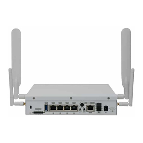
Teldat 5Ge-Rail User manual

Teldat 5Ge-Rail Router
Installation Manual
Copyright© Teldat Dm1031-I Version 1.0 09/2022 Teldat S.A.
Teldat S.A. Manual
Teldat 5Ge-Rail Router 1

Legal Notice
Warranty
This publication is subject to change.
Teldat S.A. offers no warranty whatsoever for information contained in this manual.
Teldat S.A. is not liable for any direct, indirect, collateral, consequential or any other damage connected to the deliv-
ery, supply or use of this manual.
Manual Teldat S.A.
2Teldat 5Ge-Rail Router

Table of Contents
I RelatedDocuments................................. 1
Chapter1 AboutThisGuide.................................. 2
1.1 SupportedDevices................................... 2
1.2 Who Should Read This Manual? . . . . . . . . . . . . . . . . . . . . . . . . . . . . . 2
1.3 When Should This Manual Be Read? . . . . . . . . . . . . . . . . . . . . . . . . . . . 2
1.4 WhatIsInThisManual?................................. 2
1.5 WhatIsNotInThisManual?............................... 2
1.6 How Is The Information Organized? . . . . . . . . . . . . . . . . . . . . . . . . . . . . 2
1.7 TechnicalSupport ................................... 3
Chapter 2 Teldat 5Ge-Rail Router . . . . . . . . . . . . . . . . . . . . . . . . . . . . . . 4
2.1 PowerSupply..................................... 4
2.2 HardwareMonitoring.................................. 4
Chapter 3 Components and Power Supply . . . . . . . . . . . . . . . . . . . . . . . . . . 5
3.1 Components...................................... 5
3.1.1 Frontpanel ...................................... 5
3.1.2 Rearpanel....................................... 7
3.2 MountingOptions.................................... 8
3.2.1 Assembly: Recommendations . . . . . . . . . . . . . . . . . . . . . . . . . . . . . . 8
3.2.2 Outlinedrawing..................................... 8
3.3 PowerSource..................................... 9
3.3.1 Connecting the power supply. . . . . . . . . . . . . . . . . . . . . . . . . . . . . . . 9
3.3.2 PoE......................................... 11
3.4 RESETButton.................................... 12
3.4.1 Rebootingthedevice................................. 12
3.4.2 Defaultconfiguration................................. 12
3.5 ConnectingData................................... 12
3.5.1 LANconnection ................................... 12
3.5.2 Connecting the WWAN antennas . . . . . . . . . . . . . . . . . . . . . . . . . . . . 13
3.5.3 Connecting the GPS antenna . . . . . . . . . . . . . . . . . . . . . . . . . . . . . 14
3.5.4 Configuration connection . . . . . . . . . . . . . . . . . . . . . . . . . . . . . . . 14
3.5.5 Connecting the I/O signals . . . . . . . . . . . . . . . . . . . . . . . . . . . . . . . 16
3.6 InstallingtheSIMCard ................................ 16
Teldat S.A. Table of Contents
Teldat 5Ge-Rail Router i

Chapter4 Compliance.................................... 18
4.1 ManufacturerInformation............................... 18
4.2 RiskIdentification................................... 18
4.3 SafetyWarnings................................... 21
4.4 WEEEInformation.................................. 21
4.5 REACH....................................... 21
4.6 EC Declaration of Conformity. . . . . . . . . . . . . . . . . . . . . . . . . . . . . . 21
4.7 CEMarking..................................... 22
4.8 NationalRestrictions................................. 22
4.9 OperatingFrequency................................. 22
Appendix A Technical Information . . . . . . . . . . . . . . . . . . . . . . . . . . . . . . 23
A.1 Troubleshooting................................... 23
A.2 Maintenance..................................... 23
A.2.1 Anticorrosion measures to protect the device's metal parts during transportation, storing or at its final
location....................................... 23
A.2.2 Cleaning....................................... 24
A.2.3 Softwareupdates................................... 24
A.3 Connectors ..................................... 25
A.3.1 POWERconnector.................................. 25
A.3.2 LANconnector.................................... 25
A.3.3 WWANantennaconnector............................... 25
A.3.4 GPSconnector.................................... 26
A.3.5 ConfI/Oconnector.................................. 26
A.4 TechnicalSpecifications................................ 26
A.4.1 Hardwarearchitecture................................. 26
A.4.2 LANinterface .................................... 27
A.4.3 WirelessWANinterface................................ 29
A.4.4 GPSinterface.................................... 30
A.4.5 Configurationinterface ................................ 31
A.4.6 Digital output specification . . . . . . . . . . . . . . . . . . . . . . . . . . . . . . . 31
A.4.7 Digital input specification . . . . . . . . . . . . . . . . . . . . . . . . . . . . . . . 31
A.4.8 Electrical specifications . . . . . . . . . . . . . . . . . . . . . . . . . . . . . . . . 32
A.4.9 Mechanical specifications . . . . . . . . . . . . . . . . . . . . . . . . . . . . . . . 32
A.4.10 Environmental specifications . . . . . . . . . . . . . . . . . . . . . . . . . . . . . . 33
AppendixB RadioInformation................................. 34
B.1 RFWANSpecifications................................ 34
B.1.1 Regulatory model “TLDPH00M1” compliance. . . . . . . . . . . . . . . . . . . . . . . 35
Table of Contents Teldat S.A.
ii Teldat 5Ge-Rail Router

I Related Documents
Teldat Dm704-I Configuration and Monitoring
Teldat Dm709-I LAN Interfaces
Teldat Dm748-I Software Updating
Teldat Dm772-I Configuration Interfaces
Teldat Dm781-I Cellular Interface
Teldat Dm812-I GPS Interface
Teldat Dm1030-I Teldat 5Ge User Manual
Teldat S.A. Related Documents
Teldat 5Ge-Rail Router 1

Chapter 1 About This Guide
This is the installation guide for the Teldat 5Ge-Rail router. It contains information on how to correctly install the
device in a working environment.
1.1 Supported Devices
The information included in this installation guide only applies to the Teldat 5Ge-Rail router.
1.2 Who Should Read This Manual?
This manual should be read by the support personnel who need to configure, maintain and monitor the device.
1.3 When Should This Manual Be Read?
Read this guide as soon as you are ready to familiarize yourself with the device and its components.
This manual will help you understand your new device in greater depth.
1.4 What Is In This Manual?
This installation guide contains the following information:
• A description of the features that are available in the Teldat 5Ge-Rail device.
• Technical specifications.
• Power supply requirements.
• Elements you can connect to the device while it is running.
• Installation and removal procedures for modules and power supplies.
• A description of the device LEDs and connectors.
• Troubleshooting.
1.5 What Is Not In This Manual?
This manual does not contain information regarding the device software or its configuration. For information on how
to configure this device, please see the relevant protocol manuals found on the Teldat website:
http://www.teldat.com.
1.6 How Is The Information Organized?
Each chapter focuses on a specific part of the hardware and its components. All descriptive, technical specifications
and information on a component can be found in the relevant chapter.
1 About This Guide Teldat S.A.
2Teldat 5Ge-Rail Router

1.7 Technical Support
Teldat S.A. offers a technical support service. Device software can be upgraded on a regular basis for maintenance
purposes and for new features.
Contact information:
Web: http://www.teldat.com
Tel.: +34 918 076 565
Fax: +34 918 076 566
Email: suppor[email protected]
Teldat S.A. 1 About This Guide
Teldat 5Ge-Rail Router 3

Chapter 2 Teldat 5Ge-Rail Router
2.1 Power Supply
For further information on the power supply for the Teldat 5Ge-Rail, please see Components and Power Supply on
page 5.
2.2 Hardware Monitoring
The Teldat 5Ge-Rail router's hardware is monitored via the LED panel, which provides visual information on what is
happening in the device. The LEDs indicate the state of the hardware components, whether or not there is connectiv-
ity, data flows, etc.
For further information on the LED panel, please see Components on page 5 in the following chapter.
2 Teldat 5Ge-Rail Router Teldat S.A.
4Teldat 5Ge-Rail Router

Chapter 3 Components and Power Supply
The following chapter provides detailed information on the Teldat 5Ge-Rail router chassis and its components. This
information includes:
• Components.
• Information on assembly.
• Power supply.
• RESET button.
• Data connection.
• SIM card installation.
3.1 Components
3.1.1 Front panel
The following figure shows the front panel of the device.
Fig. 1: Front Panel
The table below provides information about each connector, as well as a description:
Front panel components
Item Description
Power Power source connection.
For more information on Power Connection, refer to:
-Connecting the power supply on page 9
-POWER connector on page 25
-Electrical specifications on page 32
Conf I/O Multipurpose connector for Configuration Console and Digital I/O signals.
Configuration Console
For more information on Configuration connection, refer to:
-Configuration connection on page 14
-Conf I/O connector on page 26
-Configuration interface on page 31
Digital I/O
For more information on Digital Input/Output connection, refer to:
-Connecting the I/O signals on page 16
-Conf I/O connector on page 26
Teldat S.A. 3 Components and Power Supply
Teldat 5Ge-Rail Router 5

-Digital input specification on page 31
-Digital output specification on page 31
LAN1 LAN1/POE 2.5 Gigabit Ethernet.
Refer to PoE on page 11 for more information on PoE connection
For more information on the LAN interface, refer to:
-LAN connection on page 12
-LAN connector on page 25
-LAN interface on page 27
LAN2 LAN2. 2.5 Gigabit Ethernet.
For more information on the LAN interface, refer to:
-LAN connection on page 12
-LAN connector on page 25
-LAN interface on page 27
RST Reset button.
For further information on how the reset button works, please see RESET Button
on page 12.
GPS GPS Antenna connector.
For more information on the GPS interface, refer to:
-Connecting the GPS antenna on page 14
-GPS connector on page 26
-GPS interface on page 30
A, B, C and D WWAN Antenna connectors
The number of connectors depends on the device model (2 connectors for LTE-A
and LTE-A+ models, 4 connectors for 5G-capable models).
For more information on the antenna connections, refer to:
-Connecting the WWAN antennas on page 13
-WWAN antenna connector on page 25
-Wireless WAN interface on page 29
In addition to the connectors, the front panel also contains a set of LEDs that indicate router status.
Fig. 2: LEDs Panel
The LED panel provides information on the status of the components (indicating whether they are active or not) and
on network activity.
3 Components and Power Supply Teldat S.A.
6Teldat 5Ge-Rail Router

LEDs
LED Status Description
PWR Tricolor Green -> Device powered.
Red -> Heater active.
LAN1 / LAN2 Tricolor Green -> Link has been established.
Blinking: connection data activity.
Amber -> Test in progress.
Red -> Disconnected.
Off -> Interface off.
W Tricolor Off -> System stopped.
Red -> Interface is unavailable because it is installing, disabled
(shutdown), or due to an auto-test failure.
Amber -> Idle:
• Rapid blinking. The device has not registered in the network, or
the quality is insufficient.
• Slow blinking. WCDMA connection.
• Steady. LTE/5G connection.
Green -> Connected. Blinking: connection data activity.
SIM Tricolor Off -> System stopped.
Red -> No SIM Selected.
Amber -> SIM2 Selected.
Green -> SIM1 Selected.
3.1.2 Rear panel
The following figure shows the front panel. Here you will find the Teldat 5Ge-Rail SIM card slots.
Fig. 3: Rear Panel
The following table provides information on each connector, as well as a description:
Rear panel elements
Item Description
SIM1, SIM2 SIM Card 1-2. Slot where you can insert the SIM cards.
• SIM1: Upper Slot
• SIM2: Lower Slot
Refer to Installing the SIM Card on page 16 for more information on SIM installa-
tion.
Teldat S.A. 3 Components and Power Supply
Teldat 5Ge-Rail Router 7

GND Ground Protection Screw.
Refer to Electrical specifications on page 32 for more information on Power Con-
nection.
3.2 Mounting Options
Note
The device should be handled and installed by qualified service personnel, otherwise it could be dam-
aged or malfunction.
3.2.1 Assembly: Recommendations
Thanks to brackets in the housing, the Teldat 5Ge-Rail can be mounted on the wall or ceiling.
Wall-/Ceiling mounting
To install the device on the wall/ceiling, the mounting brackets may be readily attached to the housing. They are
screwed to the wall/ceiling using six screws.
Warning
Before drilling, make sure that there are no building installations nearby. If gas, electricity, water or
waste water lines are damaged, you may endanger your life or damage property.
• Screw the mount to the wall with the 6 screws. This will ensure the device is securely mounted.
• Make sure the device connections are accessible.
3.2.2 Outline drawing
The following outline drawing provides installation instructions:
3 Components and Power Supply Teldat S.A.
8Teldat 5Ge-Rail Router

Fig. 4: Outline drawing
3.3 Power Source
Note
Please read the following instructions carefully before connecting the router!
3.3.1 Connecting the power supply
The Teldat 5Ge-Rail supports a 24 V to 110 V nominal DC power source.
Note
Please check that the device's power input is valid for your power feeding.
If the device is below 5 °C, a heater will activate and the device will not boot until the temperature has
increased. In this state, power consumption amounts to 55 W.
The following image shows the location of the power connector.
Fig. 5: Power supply connector
There is no on/off switch or fuse. The power supply information is printed on a label found on the rear of the device.
Teldat S.A. 3 Components and Power Supply
Teldat 5Ge-Rail Router 9

This equipment requires an external overcurrent protection device. To comply with
safety regulations, a 5.0 A time-lag fuse, or a previously approved 1-amp thermo-
magnetic circuit breaker (ABB-S281-UC-K-1 or equivalent), must be installed in
the power line. Be sure to observe the correct polarity of the DC connection as the
wrong polarity may destroy the external line fuse
The Teldat 5Ge-Rail has one earth terminal (on the rear panel). It must be groun-
ded through a cable with a section measuring, at least, 2 mm2(AWG14).
This equipment must be grounded. Never deactivate the ground conductor or op-
erate the equipment in the absence of a properly installed ground conductor. Con-
tact the appropriate electrical inspection authority or an electrician if you don't
know whether suitable grounding is available. When installing or replacing the unit,
the ground connection must always be established first and disconnected last.
Fig. 6: Rear view, Protective Earth connection
3.3.1.1 Power connector pins
The power connector on this router is an M12 4-pole code Amale connector or equivalent.
PIN Signal M12 4P Code A male
1 + V DC
2 + V DC
3 0 V
4 0 V
Note
Connections 1-2 and 3-4 are redundant. We recommend keeping this redundancy to guarantee device
availability.
Note
To install the power cable using the M12 cable connector, the maximum tightening torque allowed is
0.4Nm. Higher values may damage the router connector. After its initial connection, frequent checkups
must be carried out to ensure its correct fitting.
3 Components and Power Supply Teldat S.A.
10 Teldat 5Ge-Rail Router

3.3.1.2 Power cable
The power cable is not supplied with the router. The estimated maximum consumption for this equipment is 0.5 A
(operating at 110 VDC) or 2.5 A (operating at 24 VDC). Any cable with four conductors and a gauge greater than, or
equal to, 0.75 mm2(AWG18) is acceptable. The type of cable and its gauge, however, will be determined by the
characteristics of the female connector used.
You don't need a shielded cable. However, if you intend to use one, we recommend attaching the cable to the
grounding point on the other side of the router, to the ground point on the power supply, or to both.
The cable must be certified in terms of flammability. A CE or UL marking is necessary to ensure this.
Electric current in power cables, telephone lines and communication cables is
dangerous. To prevent electric shocks, connect and disconnect the cables as
shown in the following table before installing, handling or opening the equipment
covers:
To connect To disconnect
Make sure that the power supply cable is not connected
to the device.
Disconnect the power supply cable from the power sup-
ply.
Connect all data cables. Disconnect the power supply cable from the device.
Connect the power supply cable to the device. Disconnect the data cables.
Connect the power supply cable to the power supply.
3.3.2 PoE
The Teldat 5Ge-Rail device can be powered through an Ethernet cable, provided the latter complies with the POE
802.3at standard (PoE+). The LAN1 port is enabled for this.
The image below shows how to connect the PoE injector to the device.
Fig. 7: Connecting the PoE adapter to the router
Teldat S.A. 3 Components and Power Supply
Teldat 5Ge-Rail Router 11

3.4 RESET Button
The different features of the RESET button are described below.
Fig. 8: Reset button
3.4.1 Rebooting the device
Once the device is operating normally, pressing the RESET button will restart the device.
3.4.2 Default configuration
The RESET button allows you to boot the device with its default configuration through the following steps:
• With the device switched off, keep the RESET button pressed until the device switches on.
• The POWER LED (green) will light up and the W LED will begin to blink. This blinking will continue for 10 seconds.
• For the device to boot with the default configuration, release the Reset button while the W LED is blinking (i.e., be-
fore the 10-second period expires).
Once the default configuration is running, you need to know what type of license the device has. Depending on the li-
cense, the device will operate as:
• Router: If you have a router license, the device will behave as a router. In this case, the default configuration estab-
lishes the following access IP address and mask:
IP address: 192.168.1.1
IP mask: 255.255.255.0
• 5G enabler: If you have a 5G enabler license (5Ge), the device will have a special configuration. Please see Teldat
Dm1030-I - Teldat 5Ge-Rail User Manual for further information on how to access the device and its configuration.
To find out what type of license you have, execute a ping to IP address 192.168.1.1. The device, previously con-
figured with the default configuration and duly connected by means of an Ethernet cable, will respond to the ping in-
dicating whether you are dealing with a router or a 5Ge-R.
Note
Some devices come with customized settings. As a result, the default configuration may be different to
the one shown above.
3.5 Connecting Data
The Teldat 5Ge-Rail has the following data connections.
3.5.1 LAN connection
The Teldat 5Ge-Rail incorporates two Gigabit Ethernet 10/100/1000/2500 BaseT ports with automatic MDI/MDIX.
3 Components and Power Supply Teldat S.A.
12 Teldat 5Ge-Rail Router

Fig. 9: Ethernet Ports
Note
Only the LAN1 connector is available during booting and in BIOS mode.
Note
An appropriate software license must be installed for the second LAN (LAN2) interface to work.
3.5.2 Connecting the WWAN antennas
The Teldat 5Ge-Rail has four connectors for WWAN antennas on the front panel.
To assemble or dismantle the antennas, simply plug or unplug them into or out of the connectors located on the front
panel of the router.
For more information on the antenna connectors and the RF bands supported, refer to Antenna connectors and
bands on page 29
Installing these antennas in the Teldat 5Ge-Rail is essential to improve the quality of the signal received and trans-
mitted by the cellular model.
Note
To achieve good quality performance, the Teldat 5Ge-Rail device should always have the WWAN an-
tennas installed.
Some cellular telephony technologies use the antenna diversity technique to improve the quality of the received sig-
nal. The Teldat 5Ge-Rail router family incorporates several WWAN connectors for this.
Fig. 10: WWAN connectors
When the antennas are not directly connected to the router but installed through extension cords, the minimum dis-
tance between the two of them must be 7 cm. The maximum recommended distance between the two is 25 cm.
To achieve optimum performance, the radio frequency accessories installed (antennas and cables) should be those
recommended by Teldat.
Teldat has a series of accessories (antennas for exterior installation, antennas for ceiling installation, extension
cables, etc.) that allow you to install the devices in different locations.
3.5.2.1 Placing the antenna
The orientation of the antenna and its location with respect to other wireless devices and radiation sources (such as
communication devices, personal computers, etc.) can impact device performance.
Antennas transmit and receive radio signals. Environmental factors (such as the distance between the device and
Teldat S.A. 3 Components and Power Supply
Teldat 5Ge-Rail Router 13

the base station), physical obstacles and other RF interferences can impact their performance.
For optimum coverage, follow these steps:
• Whenever possible, place the antenna where there are no physical obstacles. Obstacles between the antenna and
the base station degrade the wireless signal. Place the antenna above ground level facing the nearest base sta-
tion.
• The density of materials also affects antennas. Place them away from any type of wall, metal screens, mirrors, etc.
• Do not place the antenna near columns, which may throw shadows and reduce the coverage area.
• Keep the antenna away from metal pipes (such as those used for plumbing, air-conditioning, etc.).
• Please bear in mind that other wireless devices (such as telephones, microwaves, etc.) can temporarily interfere
with the quality of the radio signal.
• We do not recommend installing antennas near, or between, racks containing communication devices, computers,
etc. Use an extension cable and place the device outside.
The following recommendations are applicable to all wireless devices:
• Do not touch or move the antenna while the device is transmitting or receiving.
• When the antenna is transmitting, do not touch any equipment that contains devices that radiate very close to, or
touching, any exposed part of the body (particularly the face and eyes).
• Do not install the device in areas where the atmosphere is potentially explosive.
• Wireless devices can cause interferences in other devices. Do not use the device in areas where medical equip-
ment is installed.
3.5.3 Connecting the GPS antenna
The Teldat 5Ge-Rail has an QMA connector to connect an active GPS antenna .
Since the router doesn't have any internal antennas, an active 3.3V external antenna must be installed on the Teldat
5Ge-Rail to optimize the GPS signal quality.
The cable used to connect the antennas must be valid for radio frequency (RF) signal communications of up to 1.5
GHz frequencies and impedances of 50 Ohm. Please note the quality and length of an antenna cable can affect the
quality of the RF signals transmitted and received. This, in turn, will affect the device coverage and data exchange
rates.
The following image shows the location of the GPS antenna connector.
Fig. 11: GPS Connector
For further information on GPS configuration, please see the Teldat Dm812-I GPS Interface manual.
3.5.4 Configuration connection
3.5.4.1 Configuration using the local console (CONF connector)
The Teldat 5Ge-Rail has an M12 8P A-Code female connector on the front panel that provides access to the router's
local console and can operate as an asynchronous serial port. The following image shows the CONF connector loca-
tion.
3 Components and Power Supply Teldat S.A.
14 Teldat 5Ge-Rail Router

Fig. 12: Conf Connector
This connector is shared with the I/O signals. The following table shows the RS232 signals and their pin assign-
ments.
PIN Signal M12 8P A Code Female
5 RS232-TxD (Output)
8 RS232-RxD (Input)
4, 6 RS232-GND
The interface behavior or function must be pre-configured. By default, it is configured in local console mode. This
section focuses on the connection for local console mode.
To configure local console mode, connect the CONF port to an asynchronous terminal (or to a PC with terminal emu-
lation).
Note
The terminal must be configured as follows:
- Speed: 115,200 bps.
- Eight data bits.
- One stop bit.
- No parity bit.
- No flow control.
3.5.4.2 Configuration using the IP terminal (LAN1 connector)
The Teldat 5Ge-Rail includes a default configuration, which activates if the device has not been pre-configured.
The router's default configuration sets up the device with the following IP access address and mask:
• IP Address: 192.168.1.1
• IP Mask: 255.255.255.0
Note
Some devices come with customized settings. As a result, your router's default configuration may be
different to the one shown above.
This initial configuration lets you access the router's configuration console through the Telnet IP protocol. To do this,
follow these steps:
• Configure the Ethernet interface on the IP terminal (usually a PC) using an IP address within the following range
[192.168.1.2, 192.168.1.254] and mask 255.255.255.0. For example, 192.168.1.2, 255.255.255.0.
• Connect the IP terminal Ethernet interface to any of the Ethernet switch ports on the Teldat 5Ge-Rail (LAN1 con-
Teldat S.A. 3 Components and Power Supply
Teldat 5Ge-Rail Router 15

nector) using an appropriate Ethernet cable (M12 to RJ45).
• Start a Telnet session from the IP terminal to IP address 192.168.1.1 ( Teldat 5Ge-Rail default address).
• The default configuration does not ask for login credentials (user/password) to access the console.
For further information on how to configure the device, please refer to the user manuals provided by Teldat on the
documentation CD or on the web.
3.5.5 Connecting the I/O signals
The Teldat 5Ge-Rail has an M12 8P A-Code female connector on the front panel that provides one Digital Input and
one Digital Output. The following image shows the I/O connector location.
Fig. 13: I/O Connector
This connector is shared with the Conf signals. The following table shows the I/O signals and their pin assignments.
PIN Signal M12 8P A Code Female
3, 7 Digital Input
1, 2 Digital Output (Relay)
3.6 Installing the SIM Card
The Teldat 5Ge-Rail router has a Wireless WAN interface that may need a SIM card (or two) to operate.
The Teldat 5Ge-Rail has two protected SIM trays on its front panel, as shown in the following figure.
Fig. 14: SIM trays
The SIM tray assignment is as follows:
• SIM1: Upper Slot
• SIM2: Lower Slot
To access the internal SIM slots, you need to remove the SIM slot cover before you can insert the SIM card in the
appropriate slot.
(1) Use a TORX T8 screwdriver to loosen the screw of the card slot cover found on the front of the device and re-
move the cover.
(2) Press to insert the SIM card into the selected tray or to remove it from the tray.
(3) Insert the card slot cover and tighten the screw.
3 Components and Power Supply Teldat S.A.
16 Teldat 5Ge-Rail Router
For further information about signal specifications, refer to Digital output specification on page 31 and Digital
inputspecification on page 31.
Other manuals for 5Ge-Rail
1
Table of contents
Other Teldat Network Router manuals
Teldat
Teldat H1 HSDPA User manual

Teldat
Teldat ATLAS X60 User manual

Teldat
Teldat 4Ge User manual

Teldat
Teldat M1 User manual

Teldat
Teldat iM8 User manual

Teldat
Teldat K Seres User manual

Teldat
Teldat Router User manual
Teldat
Teldat 4Ge User manual
Teldat
Teldat ATLAS 60 NW User manual

Teldat
Teldat Regesta PLC User manual

Teldat
Teldat ATLAS 300 User manual

Teldat
Teldat T200 User manual

Teldat
Teldat H1 RAIL Series User manual

Teldat
Teldat 4Ge User manual

Teldat
Teldat C+ Series User manual

Teldat
Teldat M1 User manual

Teldat
Teldat H2 RAIL User manual

Teldat
Teldat C User manual

Teldat
Teldat Atlas 250 User manual

Teldat
Teldat Atlas-i70 User manual