ELECTRICAL
NOTICE: The instrument may be available with multiple pin-outs. Ensure that
all electrical connections are correct. Consult the manual for proper output
load resistance, set-point pull-up resistance and voltage requirements.
WARNING: Care must be taken to avoid any high voltages that may be present
when dealing with power supplies. The instrument is designed for Class 2
installations in accordance with IPC standards. Use Class 2 power 150 VA Max
fused.
WARNING: Do not power with isolated drive circuits that are more than 36 volts
above ground potential or could reach above 36 volts in the event of a fault.
Failure to heed this warning could result in serious personal injury and/or
damage to the equipment.
NOTICE: Power requirements are 12 to 36 VDC input. Use of an underpowered
or under-voltage supply could result in equipment damage.
NOTICE: Either the base or pin 6 must be connected to ground for proper noise
immunity and to meet CE Mark standards.
NOTICE: The serial cable length must be less than 30 meters long (unless
housed in a metal conduit) to meet CE Mark requirements.
INSTALLATION
WARNING: If poisonous or injurious gases have been used in the vacuum
system, ensure that all residues have been evacuated or flushed with inert gas
before opening the system to install the gauge tube.
NOTICE: The gauge should be installed in a clean and careful manner. Take
care not to drop the product and avoid impacts to prevent damage. Care
should be taken to prevent objects, particles or condensate from dropping
inside the gauge if mounted upside down.
WARNING: If devices employing gaseous electrical discharges are present in
the vacuum system, the discharge may couple dangerous high voltage through
the gas in the chamber directly to ungrounded conductive surfaces or electrical
conductors. Seriously injury or death can occur from contacting exposed
ungrounded conductive surfaces/conductors at high potential.
Ensure that the vacuum port to which the gauge is mounted is electrically
grounded. It is essential for personnel safety as well as proper operation that
the envelope of the gauge be connected to a facility ground. Vacuum
connections that use an O-ring for a seal such as a KF type flange or a quick
connect fitting may electrically isolate the surfaces on the other side of the
connection. This may also occur on an NPT fitting if PTFE tape is used on the
sealing surfaces. In these conditions add a ground lug on a flange bolt to
provide a ground path back to a protective earth terminal.
NOTICE: When installing the 1/8” NPT version, be certain to use the ½”
wrench flats. Do not tighten using the aluminum housing as a grip or damage
may result.
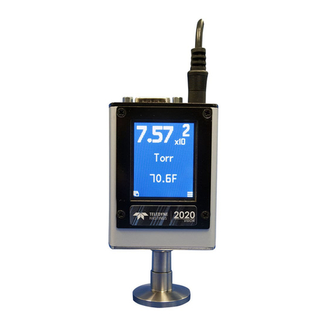
NOTICE: Do not apply excessive pressure, liquids or sharp objects to the touch
screen to avoid damage. To clean the display, breathe on the surface and
gently wipe it with a soft cotton or microfiber cloth.
WARNING: The HVG-2020A is only rated for a maximum operating pressure of
20 PSIA and using the instrument above its rated maximum overpressure of 40
PSIA (25 PSIG), could result in damage to the instrument or alter its behavior. If
operating near the maximum operating pressure, ensure there is a pressure
relief valve in the system.
WARNING: Do not install a weld stub terminated gauge in an O-ring sealed
quick connect fitting if system pressure could exceed atmospheric pressure.
QUICK START
1. Unpack and inspect all items for any obvious signs of damage due to shipment.
Immediately advise the carrier who delivered the shipment if any damage is
suspected.
2. If needed, wire the 9-pin “D” connector according to cable pinout using 24 AWG or
other suitable wire. (See table)
3. Using a unipolar DC Power Supply, set the desired operating voltage within the
range of 12 VDC to 36 VDC.
4. Transducer tube may be installed in any orientation. However, if condensation is
likely to occur, then the tube port should be orientated downward.
5. When installing 1/8” NPT style transducer tube, use the ½” wrench flats.
6. Connect power via the 9-pin cable or a 2mm bayonet-style power jack.
7. With system at atmosphere, turn on the power supply. Gauge is now reading
pressure.
8. For best accuracy, the gauge should now be zeroed.
Pump the vacuum system down to less than 0.1 Torr.
Ideally the gauge should be operated in this condition
for two hours before setting the zero.
9. To set the zero, press the menu icon, scroll to the
Set Zero menu page and press the EDIT button.
Alternatively, press and hold the Zero button until
the LEDs flash.
