126B - PAGE 8
Thestandardinletand outlet fittings for the HFM-229BFlowmeterare NPT thread in the sizeofthe
pipelisted on the drawing onpage 22, for sizesup to 3" laminar.On the 4", 6",and 8" laminars, flange
fittingsarestandard.Smoothtubulationisoptionalonallsizes.
Itissuggestedthatallconnectionsbecheckedforleaksafterinstallation.This can be done bypressuriz-
ingthetransducer(donotexceed500psigunlessthe transducer is specifically rated for higher pres-
sures)andapplyingadilutedsoapsolutiontotheflow connections.
2.5 Electrical Connections:2.5 Electrical Connections:
2.5 Electrical Connections:2.5 Electrical Connections:
2.5 Electrical Connections:
Ifapowersupplywaspurchasedfrom Hastings Instruments, installationwillconsistofconnectingthe
cable,purchased separately from the power supply,from the rear of the supply to the top of the
flowmeter.IfaHastingssupplywasnotpurchased,followtheinstructionsbelowto connect up the
flowmeter.
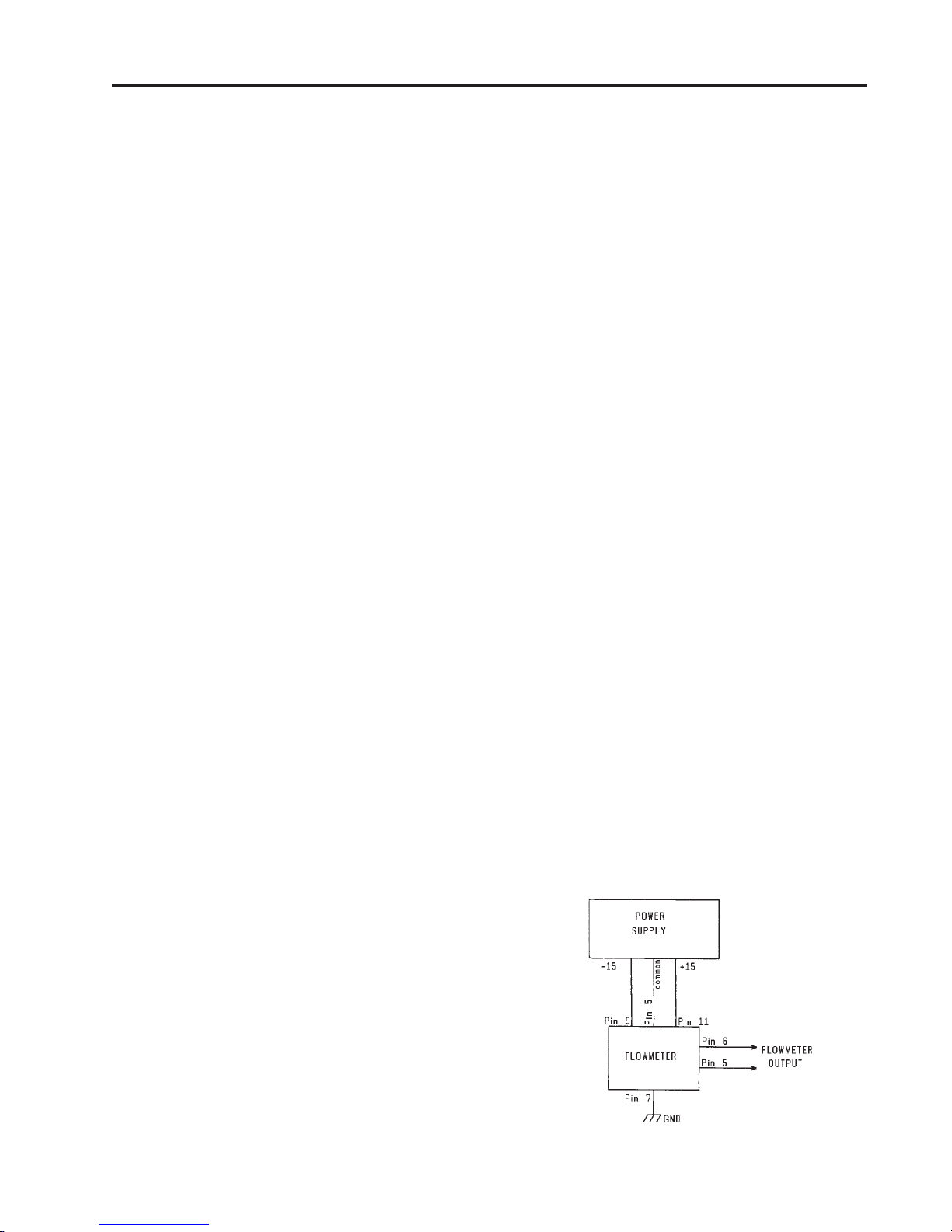
Thepowersupplyusedmustbe capable of supplying ±15VDC at ±50mA . These voltages mustbe
referencedtoacommonground.
Refer to Fig. 2.1. Connect -15VDC to pin 9 and +15VDC to pin 11.
Pin 5 is common and must be
connectedtothecommon connectionatthepower supply. Pin 7 is the case ground and it should be
connectedtothecable shield if available,andtoAC ground of the power supply.Pin 6 is the output
signalfromtheflowmeter.Thisoutputwill be 0-5VDC,5VDCbeing100%ofratedorfullflow.
2.6 Operation:2.6 Operation:
2.6 Operation:2.6 Operation:
2.6 Operation:
2.6.1 P2.6.1 P
2.6.1 P2.6.1 P
2.6.1 Poo
oo
oww
ww
wer Supply Operaer Supply Opera
er Supply Operaer Supply Opera
er Supply Operationtion
tiontion
tion
Donotconnecttransducers while the powersupply is energized.Thedisplaymay read either percentof
fullscaleoractualflowrate,dependingonthepower supplypurchased. To readflow rate,turn display
switchtodesiredchannel.
2.6.22.6.2
2.6.22.6.2
2.6.2 AmbientAmbient
AmbientAmbient
Ambient TT
TT
Temperaempera
emperaempera
emperatureture
tureture
ture
Inordertomaintaintheaccuracy of the flowmeterwithchangesinambienttemperature,itisnecessary
tokeepthetemperatureofthetransducer between 0oC and 50oC. Since some of the temperature shift
resultsina slight zero offset, better resultsareobtained if the flowmeter is re-zeroedatthe operating
temperature.Theflowmetercalibrationmay change by a factor up to 0.1%/oC.Hastings Mass
Flowmeters are for GAS flow,so DO NOT let thetemperatureand/or pressure of the gas
reachapointthatwouldcause the gas to change to a liquid state, orerroneousindicationswillresult.
2.6.3 Zero Check2.6.3 Zero Check
2.6.3 Zero Check2.6.3 Zero Check
2.6.3 Zero Check
Turn thepowersupply“ON”.Allow the flowmeter10minutestowarm up.Stop all flowthroughthe
transducerandcheck electricalzero.
CAUTION: Do not assume that all metering valves will completely shut off flow.Even a slight leakage
througha valve will cause an indication on the meter which will falsely appear to bea zero shift.
Ifnecessary,adjust the“ZERO”potentiometer,locatedonthelowerinletsideofthetransducer,until
themeterindicateszero.This zeroshouldbecheckedperiodically duringnormaloperation.
2.7 Range Changing:2.7 Range Changing:
2.7 Range Changing:2.7 Range Changing:
2.7 Range Changing:
Therangeoftheflowmetercanbechangedinthefieldifrecalibrationfacilitiesareavailable.The
instructions to change the flow range can be found in Section 4.5. In order to change the range of a
ModelHFM-230Flowmeter,anewlaminarflowelementmustbepurchasedfromthefactory.