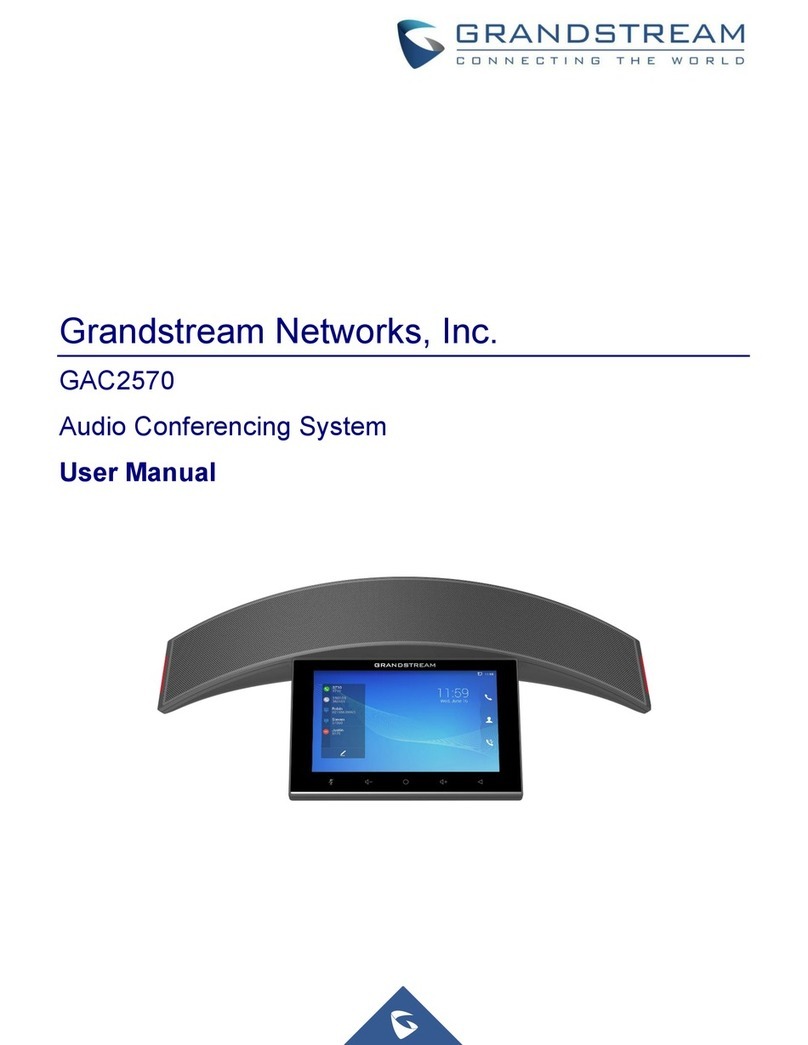
Televic TCS5500 User manual

Installation manual to
TCS5500
Televic NV/SA

All information in this document is subject to change without notice. No part of
this document may be reproduced or transmitted in any form or by any means,
electronic or mechanical, for any purpose, without the express written permission
of Televic NV.
Copyright © 2002 Televic NV. All rights reserved.
Title
Installation Manual to TCS5500
Author
DIV-EVC
Date
13/09/2011
Version
2.13
Televic NV
Leo Bekaertlaan 1
B-8870 Izegem
Tel: +32-(0)51-303045
Fax:+32-(0)51-310670
Website http://www.televic-conference.com/en/

Page | III
TCS5500 Conference & Interpretation System:
Installation Manual
Copyright© 2003 by Televic NV/SA
All rights reserved. No part of this manual shall be reproduced,
stored in a retrieval system or transmitted in any form or by any
means, without the prior written permission of the publisher, except
in case of brief quotations embodied in critical articles or reviews.
The authors of this manual have made every effort in the
preparation of this book to ensure the accuracy of the information.
However, the information in this manual is supplied without
warranty, either express or implied. Neither the authors, Televic
NV/SA, nor its dealers or distributors will be held liable for any
damages caused or alleged to be caused either directly or indirectly
by this book.
Trademarks
All terms mentioned in this manual that are known to be
trademarks or service marks have been appropriately capitalized.
Televic NV/SA cannot attest to the accuracy of this information.
Use of a term in this book should not be regarded as affecting the
validity of any trademark or service mark.
Microsoft Excel is a registered trademark of Microsoft
Corporation.


Contents
Installation manual to TCS5500 Contents ●1
Contents
TCS5500 Conference & Interpretation System: Installation Manual..III
Trademarks ..........................................................................................III
General Information 1
Safety Information.............................................................................................1
Applicable standards..........................................................................................2
TCS5500 –the Digital Conference & Interpretation System 3
Overview............................................................................................................3
Components of the TCS5500 Conference & Interpretation System..................4
TMS5500 ...............................................................................................5
TIS5500..................................................................................................5
Central equipment..................................................................................5
The system cables ..................................................................................6
The software control suite (optional).....................................................6
The technology used..............................................................................7
Power Supply.....................................................................................................7
An example............................................................................................7
PS5500...................................................................................................8
Some important data............................................................................10
TMS room equipment......................................................................................11
Delegate controller interface (INT5500) .............................................11
Digital Signal Splitter (SPL5525)........................................................13
Table top units......................................................................................14
Units for flush mounting......................................................................15
Headphone ...........................................................................................22
Microphone..........................................................................................23
Memory chip card................................................................................23
TIS Interpreter equipment................................................................................24
Interpreter desk (ID5500) ....................................................................24
Central unit.......................................................................................................25
Basic equipment of the central unit (CPU5500)..................................25
Supplementary boards in the central unit.............................................27
The rack ...............................................................................................27
Technical data......................................................................................29
Operation..............................................................................................30
Configuring the conference system 31
Overview..........................................................................................................31
Introduction to the CPU5500 central unit’s operating menu ...........................32
The startup display...............................................................................32

The lock functionality......................................................................... 32
The menu buttons................................................................................ 33
Structure of the CPU5500 central unit’s operating menu ............................... 34
Overview............................................................................................. 35
The main menu ................................................................................... 36
The conference menu (1 of 2)............................................................. 37
The conference menu (2 of 2)............................................................. 38
The interpretation menu (1 of 4)......................................................... 39
The interpretation menu (2 of 4)......................................................... 40
The interpretation menu (3 of 4)......................................................... 41
The interpretation menu (4 of 4)......................................................... 42
The AUX-IN/OUT menu (1 of 2)....................................................... 43
The AUX-IN/OUT menu (2 of 2)....................................................... 44
The System menu (1 of 2)................................................................... 45
Working with the main menu ......................................................................... 48
The main screen.................................................................................. 48
F1 function key................................................................................... 48
F2 function key................................................................................... 48
The conference menu - overview.................................................................... 49
Default values of the microphone system........................................... 49
Initializing the microphone system..................................................... 49
Choosing the conference mode........................................................... 50
Max number of simultaneously active microphones .......................... 52
Adjusting the volume settings of the loudspeaker.............................. 52
Adjusting the audio settings for the microphone................................ 52
Resetting the microphone system ....................................................... 54
Accessing the microphone options ..................................................... 54
The conference menu - example..................................................................... 56
The interpreter menu - overview..................................................................... 59
Usage................................................................................................... 59
Configuration...................................................................................... 60
Options................................................................................................ 60
Channel configuration......................................................................... 62
Booth configuration ............................................................................ 62
Auto-floor ........................................................................................... 63
Initializing the interpreter system ....................................................... 65
Rebooting the interpreter system (TIS)............................................... 65
Advanced options................................................................................ 65
The interpreter menu - example...................................................................... 68
Auxiliary menu –overview ............................................................................ 69
Usage................................................................................................... 69
The outputs.......................................................................................... 69
The inputs............................................................................................ 70
Distance Conferencing (N-1).............................................................. 70
External Equalizer............................................................................... 70
Preset configuration ............................................................................ 70
System menu –overview................................................................................ 71
Usage................................................................................................... 71
Peripherals........................................................................................... 71
Miscellaneous ..................................................................................... 72

Page | 3
IP Address............................................................................................72
IP Netmask...........................................................................................73
Time.....................................................................................................73
Date......................................................................................................73
CPU5500 Defaults...............................................................................73
Init Mode..............................................................................................73
Version.................................................................................................73
Test.......................................................................................................73
Reboot..................................................................................................73
The language menu –overview.......................................................................74
Usage....................................................................................................74
Change of subparts...........................................................................................75
Interface units.......................................................................................75
Interpreter desk ....................................................................................75
Fault detection..................................................................................................76
Survey..................................................................................................76
Troubleshooting...............................................................................................79
If problems occur … ............................................................................79
Maintenance and care ..........................................................................79
Appendix A: INT5500 Connections 81
Basic configuration..........................................................................................81
Special configurations......................................................................................83
Appendix B: Camera Control Protocol 87
Overview..........................................................................................................87
Commands ...........................................................................................87
Examples..............................................................................................88
Appendix C: Operator Desk Protocol 91
Overview..........................................................................................................91
Commands ...........................................................................................92
Examples..............................................................................................93
Appendix D: Messenger Control panel 95
Overview..........................................................................................................95
Appendix E: Cables and Connectors 97
Overview..........................................................................................................97
DML/CML5500 Connection Cable (Shielded) ..................................97
DCS5500 Connection Cable (Shielded) ..............................................98
Connection Cable (Shielded) for .........................................................98
ID5500 / INT5500/SPL5525/SPL5501/ Combi panels .......................98
CLK Cable EU5500.............................................................................99
RSU –RMU cable (roomcoupling)...................................................100
14-p flat cable ....................................................................................101
6-p flat cable ......................................................................................101
Power cable (48V) .............................................................................102
Ethernet Connection Cable................................................................102

Serial Connection cable .................................................................... 103
Connectors ........................................................................................ 104
Cable check....................................................................................... 110
Appendix F: 114
EU5500 –SPL connections 114
Extension unit (8 branches) .......................................................................... 115
Extension unit (4 loops)................................................................................ 116
Redundancy options for EU5500 , SPL5525 and Confidea-L units............. 117

General Information
Installation manual to TCS5500 General Information ●1
General Information
Safety Information
The Televic TCS5500 Digital Conference & Interpretation System
is state of the art and has been designed to meet quality.
Nevertheless, the individual components of the conference system
can cause danger for persons and material assets if the safety
requirements are neglected.
Read carefully the safety instructions and installation manual
before operating the system,
Use the conference system only as intended,
The conference system may not be set up by personnel not
familiar with the safety regulations,
Do not use the system close to water or moisture. For example
in an outdoors installation without precautions,
Openings in the enclosure may not be covered or blocked for
example by placing the equipment close to a wall. These
openings are necessary for ventilation. They ensure a reliable
operation and protect the installation from overheating,
Route the power and system cables in a way so that they are not
likely to be walked on. Also, make sure the cables and plugs
are not routed under or against heavy items as they could cause
damage,
Do not push an object or spill a liquid through the openings in
the enclosure. They could reach voltage points resulting in
electrical shortcuts. This can cause electrical shocks and fire,
Do not convert the conference system or alter it incorrectly.
Servicing this system may only be done by qualified service
personnel,
In case replacements parts are necessary, only use parts that are
approved by the manufacturer or have the same characteristics
as the original part. Using other parts may cause serious hazard
in the system,
Always plug out the system in case it is not used for a long time
or during a lightning storm. This will avoid damage due to
lightning or power line surges.

Applicable standards
ISO 2603 - 1998
IEC 914
IEC 268
EN 55013
EN 55020
EN 60065
EN 55103-1/-2
IEC60914

TCS5500
Installation manual to TCS5500 General Information ●3
TCS5500 –the Digital
Conference & Interpretation
System
Overview If you require high-quality conference and interpretation equipment
to support the communication process, then the TCS5500 Digital
Conference & Interpretation System is the solution to your
problem. The TCS5500 Digital Conference & Interpretation
System exploits all the advantages of digital communications
technology and offers its users a series of important features:
clear sound reproduction,
a full Digital System,
Flexibility in design and integration
extremely easy to operate microphone units,
audience interaction,
advanced functionality,
the possibility to be combined with an infrared Language
Distribution System.
The TCS stands for Televic Conference System –the new
generation of fixed and expandable conference and interpreter
equipment.
The TCS5500 Digital Conference & Interpretation System is the
perfect choice for fixed installations such as conference centers,
international institutions, parliaments, city halls, ...

Page | 4
Components of the TCS5500 Conference &
Interpretation System
A TCS5500 Digital Conference & Interpretation System basic
setup consists of the following components:
TMS5500 (microphone system),
TIS5500 (interpreter system),
CPU5500 (central unit, rack),
system cables,
and if required, the software control suite for the conference
system.
It is possible to extend the system in a multiple room control
system. Therefore you will need the Televic Room Coupling
System (RCS5500).

TCS5500
Page | 5
TMS5500
TMS stands for Televic Microphone System and consists of
microphones, loudspeakers, voting units, intercom (room
equipment):
INT5500 : delegate controller interface
SPL5525 : digital signal splitter
DM(L)5500 : delegate microphone
CM(L)5500 : chairman microphone
DCS(L)5500 : listening unit
IHS5500 : intercom unit
LS5500 : loudspeaker
VFB5500 : voting units
Custom units (AIP, MAOP, …)
TIS5500
TIS stands for Televic Interpretation System and consists of
interpreter units of which three different products are available
(interpreter equipment):
ID5500 : interpreter desk
PIO5500 : programmable input output panel
DIOP500 : digital input output panel
An extended amount of functionality is made available on the
interpreter unit by the easy to use interface knobs and buttons and
the LCD display.
Central equipment
The central equipment can consist of various products
CPU5500 : central unit of the system
EU5500(L) : extension unit
PRC5500 : passive room coupling unit
AIP5500 : analog input panel
AOP5500 : analog output panel
PS5500/10..20A: power supply 48V
RSU5500 : Room switching unit
RMU5500 : Room merging unit

Page | 6
The CPU5500 central unit is the core of the TCS5500 Digital
Conference & Interpretation System.
During the conference, the central unit will manage the speech of
the delegate units and the interpreter units.
The system cables
The system cables transmit the digital audio and status information.
They also provide the power supply to the interface, conference
and interpreter units.
For the correct functioning of all equipment, each specific cable
has a specific color.
The system cable has a yellow color. This yellow cable has a black
plug and a gray plug. The black plug is dedicated to an OUTPUT
(from CPU5500, INT5500, EU5500…), the gray plus is dedicated
to an INPUT (INT5500, ID5500, FOC5500…)
Use of the correct cables and a proper connection of these cables is
of utmost importance for correct functioning of the system.
Please note that the use of a regular patch cable cannot be used.
The wire section of the system cable is AWG24, and therefore
thicker than a regular patch cable (AWG26).
The software control suite (optional)
A conference manager can control the entire conference via a PC if
he uses the optional software control suite. The software control
suite provides several extra functions, next to the functionality
provided by the central unit:
Additional functions for microphone management:
the conference manager can easily monitor which delegates
have made a request to speak, which delegates are currently
speaking, activate certain microphones, etc. Two possibilities to
manage the microphones are supplied: the first is a schematic
view of the room and the delegates; the second is through a list
of names (nominative view).
Display of voting results as diagrams: the results of a voting
can be represented graphically and can, for example, be
displayed in the conference room by using a projector. Voting
in combination with badge verification is also possible.
Interpreter management: the conference manager can configure
each desk in each booth. Configuration includes assignment of
languages to interpreter units (both for the A and B channel),
operation modes, etc.
Delegate database: the delegate database allows the conference
manager to specify delegate information. This information can
then be displayed in the nominative and the schematic view of

TCS5500
Page | 7
the microphone management screens. It is also possible to use
the information contained on the badges.
The technology used
Both the control and sound transmission of the TCS5500 Digital
Conference & Interpretation System are digital, resulting in
excellent quality. The language channels are transmitted over a 16
kHz bandwidth at a 16-bit resolution.
The delegate microphone units are connected to the delegate
controller interfaces. The interfaces are connected to each other and
to the central unit by means of system cables.
Power Supply The CPU5500 has an internal power supply of 10A (500W).
However, when there is use of EU5500 extension units, or when
the internal power supply is insufficient, a separate power supply is
necessary (PS5500/10 or PS5500/20).
Two essential criteria need to be taken into account before the
installation of the TCS5500 system takes place:
the power consumption of the system must be estimated by
using the appropriate “power calculation table”. All the
units that are connected to the TMS- or TIS network have a
known power consumption that has to be taken into account
for the total power consumption.
the voltage in the TMS or TIS-network may not be lower
than 36V. This concerns specifically the cable lengths and
associated cable losses.
By means of an example, the above items are explained.
An example
The central unit forms the heart of the system from which a TIS-
network originates consisting of 6 interpreter units. The TMS-
network consists of 3 branches of 10 interface units. Each interface
has 4 microphone panels (DML5500).
The power supply to be used
Data:
Internal power supply in CPU5500: 48V / 10A
Interface unit and microphone panels asks 5W.
Interpreter unit needs 5W.
Question: Which power supply is needed?

Page | 8
Solution:
TIS: 6 * 5W = 30W
TMS: 3 * 10 * 5W = 150W
We need a power supply with a capacity of min. 180W.
The power supply 48V/10A can exactly produce 480W (branches
533W out of the net), but there must be a reasonable reserve of
20%. The internal power supply is sufficient in this case.
This example is a basic power calculation in order to estimate.
Larger installations need a more detailed calculation that takes into
account the cable length of the branches
Loss of voltage
The voltage of an interface unit may not be lower than 36V. To
calculate the loss of voltage one must take into account the number
of interface units, the devices connected to it and the length of the
cables (with its losses) connecting the interface units.
A program, PowerCalc, has been created to calculate this. The
program asks some details: the power supply, the number of
interface units, the connected devices, the branch and the distance
between the interface units. The program calculates the voltage at
each interface unit and the total cable length. If the voltage
becomes lower than 36V, a new branch must be created from the
central.
PS5500
Description
The power supply PS5500 is a 19" rack mount version. The front
panel is equipped with a rocker mains switch with built-in indicator
and two mains fuses.
The PS5500 is available in different versions, where the output
voltage is 48V and the output current is 10A or 20A.
The use of an additional power supply is needed when the internal
power supply of the CPU5500 is insufficient, or the need of more
than the available branches is needed (and therefore an extension
unit is needed).
Features & Controls
Front panel mounted mains fuses.
On/Off rocker switch with built-in indicator.
48 V DC LED indicator.

TCS5500
Page | 9
Connectivity
The 230 V mains is connected to the PS5500 by means of a
male connector at the back of the power supply. A
switched mains outlet is available at the rear of the frame.
six female Phoenix connectors are provided at the rear of
the PS5500 1U to branch off the 48 V
four female Phoenix connectors are provided at the rear of
the PS5500 4U to branch off the 48 V.
The picture bellow shows the front and rear view of the PS5500 4U
(obsolete) and the new 1U version.
Fig.: PS5500/4U
Fig.: PS5500/1U

Page | 10
Some important data
The distance between the central unit CPU5500 and the first
interface unit INT5500 or splitter SPL5525 in the branch,
may maximum be 100 m .
The distance between two splitters SPL5525 may be max.
50m
One branch may maximum consist of 10 interface units or
Splitters (depending of the total length of the system cable).
Longer cable lengths will limit this maximum number (ref:
power calculation)
A mix of INT5500’s and SPL5525’s on the same branch is
allowed
Maximum 10 interpreter units in one branch may be
connected; Longer cable lengths will limit this maximum
number (ref: power calculation)
An interface unit needs 4W, a microphone panel +0.25W
(per panel), a channel selector +1.6W, a loudspeaker +2.4W
an interpreter unit only needs 5W
The voltage of an interface unit may not be lower than 36V

TCS5500
Page | 11
TMS room equipment
From the central unit a TMS-network starts consisting of interface
units. On these interface units, microphones, channel selectors,
voting panels and loudspeaker units are connected. There are
models to be placed on the table and others are surface mounted.
Delegate controller interface (INT5500)
4 microphones and 4 channel selectors, voting or loudspeaker units
can be connected to the interface using the MIC RJ-48 and DCS
RJ-45 connector sockets. These different units can be combined to
satisfy the user demands. Some possible connection configurations
are graphically summarized in appendix A.
The interface unit has two RJ-45 shielded connector sockets
labeled IN and OUT, which will be used to connect the interface to:
1. the central unit
Use a system cable that interconnects the TMS1 (2, 3 or 4)
RJ-45 shielded connector socket from the CPU5500 and
the RJ-45 socket labeled IN.
2. another interface unit
Interconnect IN (interface) to OUT (previous interface
unit) with a system cable.
3. an extension unit
Connect the interface to a port on the extension unit. An
EU5500 can extend the network with 8 branches.
Fig.: INT5500 –CPU5500 connections
Fig.: INT5500 –EU 5500 –CPU5500 connections

Page | 12
Technical data
Dimensions (H x W x D)
85 x 182 x 42 mm
Mounting Dimensions (H x W x D)
See drawing below
Weight
Ca. 950 g
Color
Stainless steel
Housing
Metal
Part Number
71.67.5046
Fig.: INT5500 dimensions
The interface units can be mounted (screwed) at the bottom of the
tables. However when a wide trench is available, the interface units
are simply put in the trench.
Fig.: INT5500 mounting
Table of contents
Other Televic Conference System manuals
Televic
Televic D-CERNO Instruction manual
Televic
Televic Confidea G3 Troubleshooting guide

Televic
Televic Confidea User manual
Televic
Televic CONFIDEA FLEX G4 Troubleshooting guide

Televic
Televic Confidea User manual
Televic
Televic Plixus Series User manual
Televic
Televic Plixus MME User manual

Televic
Televic Confidea Instruction Manual

Televic
Televic Confidea User manual

Televic
Televic D-CERNO User manual

