Televic D-CERNO User manual

D-CERNO
Wired Conference System
Installation and User Manual


D-Cerno Wired System
Installation and User Manual
Televic Conference Systems
V1.0 - September 14, 2011
3
Table of Contents
Table of Contents ......................................................................................................................... 3
Section 1 –General Information ................................................................................................... 5
1. Copyright Statement...................................................................................................... 7
2. Trademarks ................................................................................................................... 8
3. Conformity info ............................................................................................................. 8
4. Safety Instructions......................................................................................................... 8
4.1. Important safety instructions......................................................................................... 8
4.2. Power Connections.......................................................................................................11
5. D-Cerno System Architecture ........................................................................................12
5.1. System components .....................................................................................................12
5.2. Network structure ........................................................................................................12
Section 2 –System Components ..................................................................................................15
6. Table Top Delegate units..............................................................................................17
6.1. Introduction .................................................................................................................17
6.2. Controls and indicators .................................................................................................17
6.3. Installation ...................................................................................................................19
6.4. Microphones ................................................................................................................20
6.4.1. Introduction........................................................................................................................... 20
6.4.2. Electrical and acoustic properties ........................................................................................ 20
6.5. Maintenance ................................................................................................................21
6.5.1. General .................................................................................................................................. 21
6.5.2. Cleaning ................................................................................................................................. 21
7. Central Control unit ......................................................................................................22
7.1. Introduction .................................................................................................................22
7.2. Controls and indicators .................................................................................................22
7.3. External Connections ....................................................................................................22
8. Power Supply ...............................................................................................................23

D-Cerno Wired System
Installation and User Manual
Televic Conference Systems
V1.0 - September 14, 2011
4
9. System cables...............................................................................................................23
Section 3 –Configuring the system ..............................................................................................25
10. Menu Navigation..........................................................................................................27
11. Menu overview ............................................................................................................27
Section 4 –The Menu explained ..................................................................................................31
12. Main Menu...................................................................................................................33
12.1. Headphone volume ......................................................................................................33
12.2. Conference modes........................................................................................................33
12.2.1. Direct Access ......................................................................................................................... 33
12.2.2. Activation mode .................................................................................................................... 33
12.2.3. Override (1-8) ........................................................................................................................ 33
12.2.4. With request.......................................................................................................................... 34
12.3. Microphone Limit .........................................................................................................34
12.4. Microphone preset .......................................................................................................34
12.5. Audio out .....................................................................................................................35
12.6. Audio In .......................................................................................................................35
12.7. External processing.......................................................................................................35
12.7.1. Independent aux settings...................................................................................................... 35
12.7.2. Remote Conferencing............................................................................................................ 35
12.7.3. External Equalizer.................................................................................................................. 36
12.8. Settings menu ..............................................................................................................37
12.8.1. Factory settings ..................................................................................................................... 37
12.8.2. System info ............................................................................................................................ 37
Section 5 –Appendix ...................................................................................................................39
13. Default Settings ............................................................................................................41
14. Technical Data..............................................................................................................42
14.1. Electrical and Electro Acoustical Characteristics.............................................................42
14.2. Mechanical Characteristics............................................................................................42
14.3. Environmental Characteristics.......................................................................................42
14.4. System limits ................................................................................................................42

D-Cerno Wired System
Installation and User Manual
Televic Conference Systems
V1.0 - September 14, 2011
5
Section 1 – General Information


D-Cerno Wired System
Installation and User Manual
Televic Conference Systems
V1.0 - September 14, 2011
7
1. Copyright Statement
No part of this publication or documentation
accompanying this product may be reproduced in
any form or by any means or used to make any
derivative such as translation, transformation, or
adaptation without the prior written permission of
the publisher, except in case of brief quotations
embodied in critical articles or reviews. Contents are
subject to change without prior notice.
Copyright© 2011 by Televic Conference NV. All rights
reserved.
The authors of this manual have made every effort in
the preparation of this book to ensure the accuracy
of the information. However, the information in this
manual is supplied without warranty, either express
or implied. Neither the authors, Televic Conference
NV, nor its dealers or distributors will be held liable
for any damages caused or alleged to be caused
either directly or indirectly by this book.

D-Cerno Wired System
Installation and User Manual
Televic Conference Systems
V1.0 - September 14, 2011
8
2. Trademarks
All terms mentioned in this manual that are known
to be trademarks or service marks have been
appropriately capitalized. Televic Conference NV
cannot attest to the accuracy of this information. Use
of a term in this book should not be regarded as
affecting the validity of any trademark or service
mark.
3. Conformity info
The D-Cerno Wired Conference system is compliant
with following standards:
EN60065
EN55103-1/-2
IEC60914
4. Safety Instructions
The D-Cerno Conference system is state of the art
and has been designed to meet quality.
Nevertheless, the individual components of the
conference system can cause danger for persons and
material assets if
the conference system is not used as intended,
the conference system is set up by personnel not
familiar with the safety regulations,
the conference system is converted or altered
incorrectly,
the safety instructions are not observed.
4.1. Important safety
instructions
1. Read Instructions
All the safety and operating instructions should be
read before the product is operated.
1. Retain Instructions
The safety and operating instructions should be
retained for future reference.
2. Heed Warnings
All warnings on the product and the operating
instructions should be adhered to.
3. Follow Instructions
All instructions for installation or operating / use
should be followed.
4. Cleaning
Unplug this product from the wall outlet before
cleaning. Do not use liquid cleaners or aerosol
cleaners. Use a damp cloth for cleaning.
5. Ventilation
Slots and openings in the cabinet are provided for
ventilation and to ensure reliable operation of the
product and to protect it from overheating. These
openings must not be blocked or covered. The
openings should never be blocked by placing the
product on a bed, sofa, rug, or other similar surface.
This product should not be placed in a built-in
installation such as a bookcase or rack unless proper
ventilation is provided or the manufacturer's
instructions have been adhered to.
6. Heat
The product should be situated away from heat
sources such as radiators, heat registers, stoves, or
other products (including amplifiers) that produce
heat.
7. Attachments
Do not use attachments not recommended by the
product manufacturer as they may cause hazards.
8. Water and Moisture
Do not use this product near water or in a moistures
environment - for example, near a bath tub, wash
bowl, kitchen sink, or laundry tub; in a wet

D-Cerno Wired System
Installation and User Manual
Televic Conference Systems
V1.0 - September 14, 2011
9
basement; or near a swimming pool, in an
unprotected outdoor installation; and the like.
9. Accessories
Only use attachments/accessories specified by the
manufacturer. Do not place this product on an
unstable cart, stand, tripod, bracket, or table. The
product may fall, causing serious injury to a child or
adult, and serious damage to the product. Use only
with a cart, stand, tripod, bracket, or table
recommended by the manufacturer, or sold with the
product. Any mounting of the product should follow
the manufacturer's instructions, and should use a
mounting accessory recommended by the
manufacturer.
10. Moving
A product and cart combination should be moved
with care. Quick stops, excessive force, and uneven
surfaces may cause the product and cart
combination to overturn.
11. Power Sources
This product should be operated only from the type
of power source indicated on the marking label. If
you are not sure of the type of power supply to your
home, consult your product dealer or local power
company. For products intended to operate from
battery power, or other sources, refer to the
operating instructions.
12. Power Lines
An outdoor system should not be located in the
vicinity of overhead power lines or other electric light
or power circuits, or where it can fall into such power
lines or circuits. When installing an outdoor system,
extreme care should be taken to keep from touching
such power lines or circuits, as contact with them
might be fatal. U.S.A. models only - refer to the
National Electrical Code Article 820 regarding
installation of CATV systems.
13. Grounding or Polarization
Do not defeat the safety purpose of the polarized or
ground-type plug. A polarized plug has two blades
with one wider than the other. A grounding type plug
has two blades and a third grounding prong. The
wider blade or the third prong are provided for your
safety. If the provided plug does not fit into your
outlet, consult an electrician for replacement of the
obsolete outlet.
14. Power-Cord Protection
Power-supply cords should be routed to that they
are not likely to be walked on or pinched by items
placed upon or against them, paying particular
attention to cords at plug, convenience receptacles,
and the point where they exit from the product.
15. Lightning
For added protection for this product during a
lightning storm, or when it is left unattended and
unused for long periods of time, unplug it from the
wall outlet. This will prevent damage to the product
due to lightning and power-line surges.
Not applicable when special functions are to be
maintained, such as evacuation systems
16. Overloading
Do not overload wall outlets, extension cords or
integral convenience receptacles as this can result in
a risk of fire or electric shock.
17. Object and Liquid Entry
Never push objects of any kind into this product
through openings as they may touch dangerous
voltage points or short-out parts that could result in
a fire or electric shock. Never spill liquid of any kind
on the product.
18. Inflammable and Explosive Substance
Avoid using this product where there are gases, and
also where there are inflammable and explosive
substances in the immediate vicinity.
19. Heavy Shock or Vibration
When carrying this product around, do not subject
the product to heavy shock or vibration.

D-Cerno Wired System
Installation and User Manual
Televic Conference Systems
V1.0 - September 14, 2011
10
20. Servicing
Do not attempt to service this product yourself as
opening or removing covers may expose you to
dangerous voltage or other hazards. Refer all
servicing to qualified service personnel.
21. Damage Requiring Service
Unplug this product from the wall outlet and refer
servicing to qualified service personnel under the
following conditions:
a. When the power-supply cord or plug is
damaged.
b. if liquid has been spilled, or objects
have fallen into the product.
c. If the product has been exposed to rain
or water.
d. If the product does not operate
normally by following the operating
instructions. Adjust only those controls
that are covered by the operating
instructions as an improper adjustment
of other controls may result in damage
and will often require extensive work by
a qualified technician to restore the
product to its normal operation.
e. If the product has been dropped or
damaged in any way.
f. When the product exhibits a distinct
change in performance-this indicates a
need for service.
22. Replacement Parts
When replacement parts are required, be sure the
service technician has used replacement parts
specified by the manufacturer or have the same
characteristics as the original part. Unauthorized
substitutions may result in fire, electric shock, or
other hazards.
23. Safety Check
Upon completion of any service or repairs to this
product, ask the service technician to perform safety
checks to determine that the product is in proper
operating condition.
24. Coax Grounding
If an outside cable system is connected to the
apparatus, be sure the cable system is grounded.
U.S.A. models only: Section 810 of the National
Electrical Code, ANSI/NFPA No.70-1981, provides
information with respect to proper grounding of the
mount and supporting structure, grounding of the
coax to a discharge apparatus, size of grounding
conductors, location of discharge unit, connection to
grounding electrodes, and requirements for the
grounding electrode.

D-Cerno Wired System
Installation and User Manual
Televic Conference Systems
V1.0 - September 14, 2011
11
4.2. Power Connections
For permanently connected equipment, a readily
accessible disconnect device shall be incorporated in
the fixed wiring; For pluggable equipment, the
socket-outlet shall be installed near the equipment
and shall be easily accessible.
This label may appear on the bottom of the
apparatus due to space limitations.
The lightning flash with an
arrowhead symbol, with an
equilateral triangle, is intended to
alert the user to the presence of
un-insulated ‘dangerous voltage’
within the products enclosure that may be of
sufficient magnitude to constitute a risk of electric
shock to persons.
The exclamation mark within an
equilateral triangle is intended to
alert the user to the presence of
important operating and
maintenance (servicing)
instructions in the literature accompanying the
appliance.
Warning:
To reduce the risk of fire or electric
shock, do not expose this appliance to
rain or moisture. Do not open the
cabinet; refer servicing to qualified
personnel only.
Warning:
To prevent electric shock, do not use
this (polarized) plug with an extension
cord receptacle or other outlet unless
the blades can be fully inserted to
prevent blade exposure.
Attention:
Installation should be performed by
qualified service personnel only in
accordance with the National Electrical
Code or applicable local codes.
Attention:
Equipment with or without ON/OFF
switches have power supplied to the
equipment whenever the power cord is
inserted into the power source;
however, the equipment is operational
only when the ON/OFF switch is in the
ON position. The power cord is the
main power disconnect for all
equipment.

D-Cerno Wired System
Installation and User Manual
Televic Conference Systems
V1.0 - September 14, 2011
12
5. D-Cerno System
Architecture
The D-Cerno system is a digital discussion system for
small to medium size conference rooms.
The main characteristics of the system are:
Cristal clear audio reproduction: digital signal
processing, high quality GSM interference free
microphone and loudspeaker, resulting in
excellent intelligibility.
Attractive, stylish design: contemporary,
unobtrusive and low profile, fitting into
modern and traditional style conference rooms
Plug and Play: easy installation, up and running
in no time, ideal for frequently changing
environments
High reliability: built-in redundancy feature –
touch sensor technology, hygienic, easy to
clean, equal performance over the entire
lifespan of the product.
5.1. System components
A D-Cerno system consists out of the following
components:
Central unit (Art. 71.98.0320)
oD-Cerno CU
oD-Cerno PS
oMains cable
oConference system cable (2m)
oQuick guide
Delegate unit (Art. 71.98.0301)
oD-Cerno D
oConference system cable (2m)
Chairman unit (Art. 71.98.0302)
oD-Cerno C
oConference system cable (2m)
Spare power supply (Art. 71.98.0340)
oD-Cerno PS
oMains cable
System cables, available in different lengths
(see chapter System cables)
Detailed info about the different components can be
found in Section 2 of this manual.
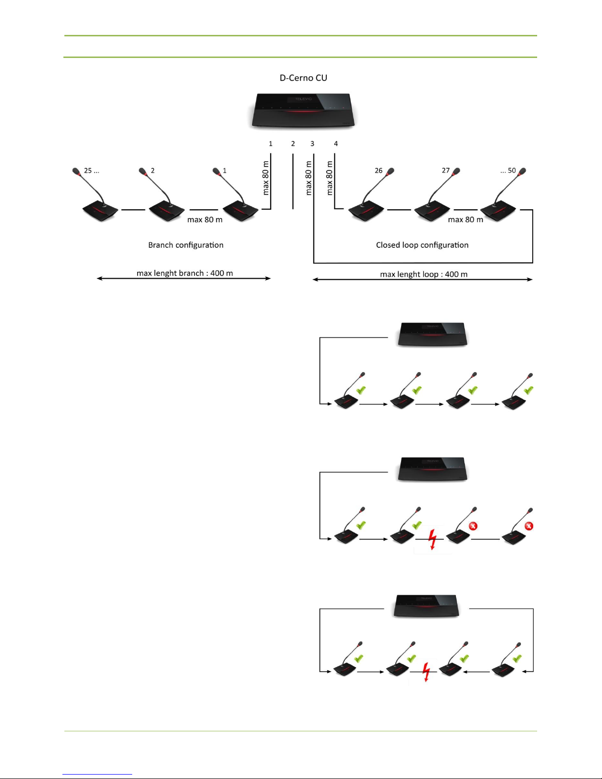
5.2. Network structure
The central unit can control and power a total of 50
units over the four available conference ports.
The network can be structured in two way:
Branch configuration
Closed loop configuration
Each branch, loop can handle a maximum of 25 units
if the total cable length is respected.
The total cable length of a branch / loop cannot
exceed the maximum of 400 m.
The max cable length between units or between
units and central unit is 80 m.
The maximum power consumption of a unit is 2W.
Below a graphical representation of a D-Cerno
configuration.
At the left side a branch configuration connected to
port 1.
At the right a closed loop configuration between port
3 and 4.
D-Cerno Wired System
Installation and User Manual
Televic Conference Systems
V1.0 - September 14, 2011
13
Figure 5.1 : D-Cerno network
Designing a system in a closed loop configuration
provides a redundant system and thus increases the
reliability of the system.
If for some reason a cable or unit gets defective the
system stays operational.
The units have the possibility to detect the flow of
the signal automatically providing a free port
selection. If at some point no signal is provided
anymore, automatically the signal flow will be
reversed. As a result the system configuration stays
operational.
The figures below illustrates:
Branch configuration in normal operation
Branch configuration with cabling error
Loop configuration with cabling error
Figure 5.2 : D-Cerno branch configuration, no error
Figure 5.3 : D-Cerno branch configuration, cable error
Figure 5.4 : D-Cerno loop configuration, cable error


D-Cerno Wired System
Installation and User Manual
Televic Conference Systems
V1.0 - September 14, 2011
15
Section 2 – System Components


D-Cerno Wired System
Installation and User Manual
Televic Conference Systems
V1.0 - September 14, 2011
17
6. Table Top Delegate
units
6.1. Introduction
The contribution units consist out of delegate and
chairman units. Both are used for speech
reinforcement in a conference room. The chairman
units are used to guide and control an ongoing
discussion.
6.2. Controls and
indicators
The D-Cerno delegate units have the following
features:
1. Microphone touch sensor button:
Activation/deactivation of the microphone.
Indication LEDs show the status of the
microphone. (red : active, green : request)
2. Loudspeaker:
Distributes the floor channel. Mutes in case
microphone is active.
3. Headphone connector:
Connection of headphone to the unit. Mono-
and stereo headphones can be used.
4. Volume touch sensor buttons:
Change the volume level of the headphones.
Remark : volume change is only possible when a
headphone is connected
5. Microphone
6. Led bar
Indicates the status of the unit.
Red : unit is active
Green : unit is in request mode
Pressing the Next-in-line or PRIOR button on a
chairman unit is indicated by illuminating the
corresponding part of the led bar.
7. NEXT button: (chairman unit only)
Grants the floor to the next delegate in the
waiting list.
8. PRIOR button: (chairman unit only)
permanently deactivates the microphone of all
active units.


D-Cerno Wired System
Installation and User Manual
Televic Conference Systems
V1.0 - September 14, 2011
19
Figure 6.2.1: D-Cerno Discussion Unit
Figure 6.2.2: D-Cerno Chairman Unit
6.3. Installation
D-Cerno units offer free input/output connectivity to
allow flexible cabling.
The delegate units can be connected as a daisy chain
branch or in loop to ensure redundancy and increase
reliability.
Figure 6.3: D-Cerno connectivity

D-Cerno Wired System
Installation and User Manual
Televic Conference Systems
V1.0 - September 14, 2011
20
Make sure that the units are not positioned too close
to each other. It is recommended to keep a distance
of 1m between the units to prevent howling.
The recommended speaking distance for people to
speak to the microphone is between 20 to 40 cm.
6.4. Microphones
6.4.1. Introduction
The D-Cerno microphone has a uni-directional
response for optimum performance even in noisy
conditions, and has a very low susceptibility to
interference from mobile phones.
6.4.2. Electrical and
acoustic properties
Table 6.4.2: Microphone characteristics
Transducer type
Back electret (condenser)
Operating principle
Pressure gradient
Polar pattern
Uni-directional,
cardioid
Frequency response
130 Hz –150000 Hz
Nominal impedance
1kOhm (at 1 kHz, drop resistance =
1k2, Vdd = 3.3VDC )
Load impedance
> 5kOhm
Max.SPL at 1 kHz
120 dB SPL
Free field sensitivity
7mV/Pa, +/- 3 dB at 1 kHz or
(-43dB, 0dB=1V/Pa at 1kHz)
Power supply
3.3V DC, 0.5 mA
Consumption
0.5 mA (without LED ring);
max. 25 mA (with illuminated ring)
Other manuals for D-CERNO
3
Table of contents
Other Televic Conference System manuals

Televic
Televic D-CERNO User manual

Televic
Televic TCS5500 User manual

Televic
Televic Confidea User manual

Televic
Televic Confidea G3 User manual

Televic
Televic Plixus Series User manual

Televic
Televic D-CERNO Instruction manual

Televic
Televic Confidea G3 Troubleshooting guide

Televic
Televic Confidea G3 User manual

Televic
Televic CONFIDEA FLEX G4 Troubleshooting guide

Televic
Televic Confidea Instruction Manual


