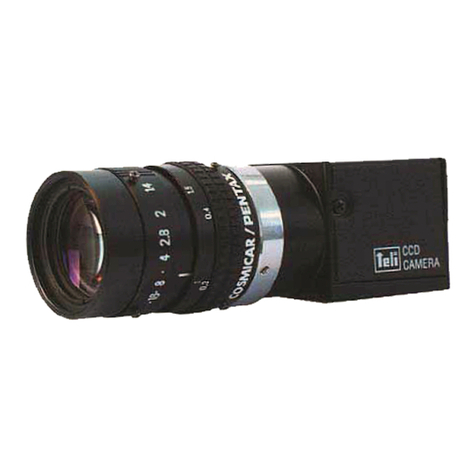
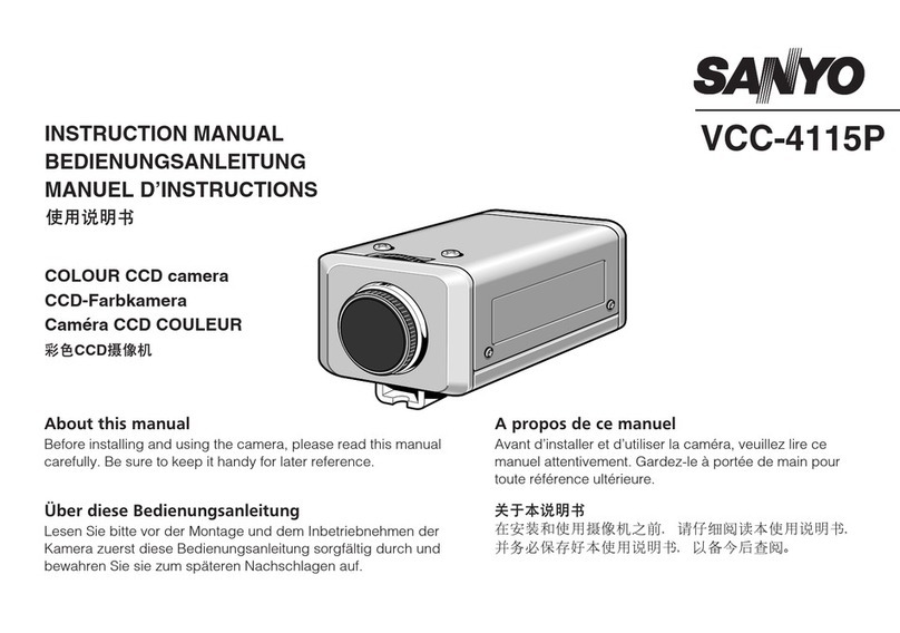
Teli CS8420Ci User manual

CCD Monochrome
Video Camera
CS8420Ci(CCIR)
Operation Manual
CONTENTS
1.FEATURES ・・・・・・・・・・・・・・・・・・・・・・・・・・・・ 2
2.PRRECAUTION ・・・・・・・・・・・・・・・・・・・・・・・・・ 2
3.CONTROLS AND ADJUSTMENT ・・・・・・・・・・ 3
4.CONNECTIONS ・・・・・・・・・・・・・・・・・・・・・・・・ 6
5.OPERATION ・・・・・・・・・・・・・・・・・・・・・・・・・・・ 8
6.SUPPLEMENTAL INFORMATION ・・・・・・・・・ 9
7.TROUBLE-SHOOTING GUIDE ・・・・・・・・・・・ 10
8.SPECIFICATIONS ・・・・・・・・・・・・・・・・・・・・・・ 10
9.CONSTITUTION ・・・・・・・・・・・・・・・・・・・・・・・・ 12
10.HOW TO FIX CAMERA ・・・・・・・・・・・・・・・・・・ 13
11.APPEARANCES ・・・・・・・・・・・・・・・・・・・・・・・・ 14
12.MAINTENANCE ・・・・・・・・・・・・・・・・・・・・・・・・ 15
For customer Use:
Enter below the Serial No. which is located on bottom chassis
of the camera.
Retain this information for future reference,
Model No. CS8420Ci
SerialNo.
T
O
KY
O
ELE
C
TR
O
NI
C
IND
US
TRY
CO
.
,
LTD
.
TOKYO ELECTRONIC INDUSTRY CO. , LTD.TOKYO ELECTRONIC INDUSTRY CO. , LTD.
T
O
KY
O
ELE
C
TR
O
NI
C
IND
US
TRY
CO
.
,
LTD
.
1
INFORMATION
This equipment generates and uses radio frequency energy and if not installed
and used properly, that is, in strict accordance with the manufacture’s
instructions, may cause interference to radio and television reception. If does
so, which can be determined by turning the equipment off and on, the user is
encouraged to try to correct the interference by one or more of the following
measures:
・Reorient the receiving antenna;
・Relocate this equipment with respect to the receiver;
・Move this equipment away from the receiver;
CAUTION
To prevent electric shock, do not use the polarized plug of the AC
Power adapter with an extension cord, receptacle or other outle
t
unless the blades can be fully inserted to prevent blade exposure.
When the camera is used within an electromagnetic field, beat
interference(vertical, horizontal or diagonal stripes) may be
created in the video output. If this occurs, take measures on the
source of the electromagnetic waves to prevent the emissions
from affecting the video output.
Such measures are particularly necessary on systems with servo
motors, inverters and other equipment that tends to generate
electromagnetic waves.
Do not subject the camera to strong shocks, as this may result in
failure or breakage.
When the camera is used on system which subject the camera
connector to strong shocks, the camera connector may suffer
damage. If the camera is used on such systems, the connector
plug should be fastened to the camera with the optional camera
connector bracket.
WARNING
TO PREVENT FIRE OR SHOCK HAZARD, DO NOT EXPOSE
THIS APPLIANCE TO RAIN OR MOISTURE.
This equipment should be used with DC12V only.
Do not use any other power source.

2
・Plug this equipment into a different outlet so that this equipment
and receiver are on different branch circuits.
If necessary, the user should consult the dealer or an experienced
radio/television technician for additional suggestions.
Thank you for purchasing the TELI
CS8420Ci TV B/W camera featuring
compact and lightweight.
To take best advantage and gain the most service from your camera, read this
operation manual carefully and thoroughly.
1.FEATURES
* Compact and light weight
* Available External sync-operation
* Equipped with an electronic shutter for fast moving subjects for better
definition picture.
2.PRECAUTION
(1) This equipment should be used with DC12V only. To prevent electric
shocks and fire hazards, do not use any other power source.
(2) The CS8420Ci is designed to be used with CCIR monochrome television
signals. It cannot be used for playback with a television of a different
standard.
(3) Please handle the equipments carefully.
(4) Do not point your camera lens directly into sunlight or strong artificial
light. This might cause irreparable damage to the image sensor.
Also, be sure to use the lens cap when the camera is not in use.
(5) Do not expose the camera unit to high temperatures. For example, do not
place it near a stove for long periods, or in direct sunshine or in a car in
hot weather. Heat may cause some malfunction.
(6) Keep the camera clean. Dust can damage the camera and cause trouble in
moving parts.Take particular care to avoid the entry of sand or grit when
changing the camera lens.
(7) This camera is not protected with an anti-dust glass cover. Make sure to
put a lens or lens cap to protect the image pickup plane from dust and/or
scratch even when the camera is not in use. Before mounting a lens to the
camera, remove dust from the CCD image plane. Don't use any organic
solvent other than ethyl alcohol to remove dust or stain from the CCD
plane. To avoid condensation trouble, when you need to move the camera
from/into cold/hot room, it's advisable that you leave the camera lying
around at a new location for a while before starting to use it.
(8) Avoid jolting the equipments or exposing it to vibration.
(9) Never attempt to dismantle the equipments.
3
(10) Avoid folding or stretching the camera cable or other connection cable
between equipments.
(11) When the cabinet is dusty, clean by gently wiping with soft cloth. And
avoid the use of strong cleaning agents such as benzine or alcohol as they
maydamagethecabinet.
3.CONTROLSANDADJUSTMENT
Get to know the name and function of every parts of your camera.
That way, you can take advantage of every applications to take beautiful
pictures.
The body and accessories shown below.
3-1.Camera Rear Panel
(1) GAIN adjustment pot
Turn it clockwise to increase video gain.
(2) VIDEO OUT connector
The composite video signal is come out from this connector which is
employed with BNC type.
(3) DC IN/SYNC connector
This connector is composed of 12pins, and DC12V, HD, VD-input,
Video output and so on, their assignment are as the table in page8
for more detail.
3-2.Explanation of internal selection switches
The internal structure of this camera is as shown in the figure below.
Side view after opening the camera cover
(2)
(1)
(3)
VIDEO
OUT
DCIN
/SYNC
MG
HD
・
VD IN/OUT selection (S1)
External SYNC signal inupt
impedance selection(S2)
CONNECTOR BOARD

4
Top view after opening the camera cover
(1) Method of setting the different modes
The different modes can be set using the switch S3 in the PROCESS board. The mode
can be selected by moving the DIP switches 1 to 6 to the left or the right position.
Each switch becomes OFF in the left position and ON in the right position.
(*). Factory setting position
Switch setting position
No. Function name OFF ON
1 Shutter speed setting
2 Shutter speed setting
3 Shutter speed setting
Please look over the a clause
of method of setting the
electronic shutter speed
4 Shutter enable (*) disable
5 CCD operation mode Field store (*) Frame store
6 Please set ON Don’t use (*) Use ON only
(2) Method of setting the electronic shutter speed
The shutter speed can be set using the switch S3 in the PROCESS board.
The relationship between the switch position and the shutter speed is as
follows.
Switch setting position
Shutter speed 1 2 3
1/50 OFF OFF OFF
1/120 ON OFF OFF
1/250 OFF ON OFF
1/500 ON ON OFF
1/1000 (*) OFF OFF ON
1/2000 ON OFF ON
1/4000 OFF ON ON
1/10000 ON ON ON
Video output AC coupling
/DC coupling selection
Selection of different modes
Electronic shutter speed selection
GAIN selection
O N
16
O
N
1
2
3
4
5
6
MODE
DC ACF M
PROCESS BOARD
(1)
(2) (3)
5
(3) HD・VD output
HD and VD pulses are come out from pin 6-5(GND) for HD, and pin 7-12
(GND) for VD of DC IN/SYNC connector on the rear panel by the following
measures when the system is required.
(4) HD・VD IN/OUT selection method
TheHD・VD IN/OUT selection can be made using the switch S1 in the
CONNECTOR board.
This switch will have been set to the HD・VD IN position at the time of
shipment from the factory. To change this setting to HD・VD OUT, set S1 as
shown in the figure in page3.
(5) External SYNC signal input impedance selection method
The external SYNC signal input impedance can be selected using the
switch S2 in the CONNECTOR board.
At the time of shipment from the factory, this switch will have been set to
the High Impedance position. To change this setting to 75Ω, set the switch
S2 as shown in the figure in page3.
(6) Video output AC coupling/DC coupling selection method
The AC coupling /DC coupling selection can be made using the switch S1
in the PROCESS board.
This switch will have been set to the AC coupling position at the time of
shipment from the factory. To change this setting to DC coupling, set S1 as
shown in the figure below.
(7) GAIN selection method
The gain becomes fixed when this switch is at the “F” position (FIX).
When this switch is set to the “M” position (MG ; Manual Gain), the gain
can be adjustment Gain adjustment pot. (The switch is set to the “M”
position when shipped from the factory.)
MANU
S2
FIX
S2
DC coupling output AC coupling output
S1S1

6
4.CONNECTION
When installing the CS8420Ci camera to your system, you have to connect
between equipments.
4-1. Typical connection
*AC adapter CA130B is an optional accessory, make choice of the most
appropriate power supply system, depending on the application.
*Typical connection of CS8420Ci. There are two connectors of “VIDEO OUT ”,
and “DC-IN/SYNC “ at the rear panel on the camera.
BNC
BNC
BNC BNC
HD VD/VS/SYNC
CCD CAMERA
CS8420Ci
(rear panel)
BNC
SERIALNo.
CLOCKOUT
VDIN
VIDEOOUT
HDIN
AC100VIN
TOKYOELECTRONICINDUSTRYCO.,LTD.
CAMERA
BNC
HIGH‑75Ω VIDEOOUTVIDEOIN
*Connect external sync generator, if necessarry
CAMERA CABLE (optional accesorry )
AC100V
50/60Hz
CAMERA ADAPTER
CA130B/CA140
(rear panel)
Video monitor
(rear panel)
Video cable
*Be sure to connect one of the two.
AC100V
50/60Hz
Video cable
VIDEO
OUT
DCIN
/SYNC
MG
!
Set75Ωvideooutput.
NOTE
CAUTION
When using the camera on systems that accept EC(EMC) directive,
be sure to use the optional shielded camera cable (CPSC3000 or
e
q
uivalent).
!
7
4-2.Connection Between Other Equipments Excluding CA130B
BNC CONNECTOR:HR10A-10P-12S
(optional accesorry)
Refer to page 8, pin assignment
+12V
GND
HIGH‑75Ω VIDEOIN
CCD CAMERA
CS8420Ci
(rear panel)
VideoMonitor(rearpanel)
Video cable
*Be sure to connect one of the two.
AC100V
50/60Hz
BNC BNC
HD
VD/VS/SYNC
*Connect with the
SYNC generator,
if necessarry.
VIDEOOUT
VIDEO
OUT
DCIN
/SYNC
MG
NOTES
Set 75
Ω
video output.
CAUTION
When using the camera on systems that accept EC (EMC)
directives, be sure to use typical connection in page 6.
!
D3002794A

8
4-3. DC IN/SYNC connector pin assignment
The connector is combined with DC12V input, and some other, and
recommended to use the system including an image processor.
They are composed of 12 pins, and the pin assignment is as followings.
Camera connector : HR10A-10P-12P (Maker : Hirose denki)
External synchronization
Pin
No. HD and VD VS/SYNC
Internal
synchronization
1 GND GND GND
2 +12V +12V +12V
3 Video output (GND) Video output (GND) Video output (GND)
4 Video output (signal) Video output (signal) Video
output(signal)
5 HD input (GND) HD output (GND)
6 HD input (signal) HD output (signal)
7 VD input (signal) VS/SYNC input (signal) VD output (signal)
8
9
10 GND GND GND
11 +12V +12V +12V
12 VD input (GND) VS/SYNC (GND) VD output (GND)
* HD, VD output is available for internal switch selection.
(1) DC12V input
Connect pin number 2 and/or 11 for DC12V(HOT) and Pin 1 and/or
10 for GND.
(2) Video output
Composite CCIR video output (VS) is output from 4 (HOT) and 3 (GND).
(3) Input pulses for external sync
When required external sync-operation between other equipments, use it
her one of pulses for HD/VD, VS or SYNC. And input HD pulse from pin
number6-5 (GND) and VD from pin 7-12 (GND) for HD/VD external sync
operation. And input VS or SYNC from pin 7 and 12 (GND) for external sync
operation by VS or SYNC.
CAUTION
There are two video output which are from VIDEO OUT (BNC)
and DC IN/SYNC pin 4-3 (GND).
Do not use both of them same time, because it may occur double
termination with the video output, and the video output will be
half.
!
9
5.Operation
(1) After the connection equipments, turn the power switch for the video
monitor on at the first.
(2) Turn the power switch for the camera to ON, and make sure the image
appears on the monitor screen.
(3) Adjust the lens aperture for the proper image brightness.
(4) Adjust the focus ring on the lens for the sharpest picture looking at the
monitor.
6.SUPPLMENTALINFORMATIONS
(1) Illuminance for better picture
“illuminance” (also called “luminance”) is intensity or brightness of light,
expressed in lx or foot-candles (fc).
The CS8420Ci is designed to provide best pictures under the condition, of
a 1500 lx (130 fc) illuminance.
To obtain good pictures under very bright object, the use of an ND (neutral
density) filter is recommended.
IMPORTANT
To ensure maximum performance, be sure to keep the inside of
lens and inner part of camera module free from dust or
fingerprint.
CAUTION
If the lens (C-mount) size exceeds 100mm in diameter, 170mm in
length and 1000g in weight, both the camera and lens should be
secured.
Because the camera housing-strength is not enough to support
such a weight or stress, may cause damage it.
CAUTION
Don’t equip a lens to incline. And please use lens which have n
o
flaw and dust at mount hole, or the lens maybe don’t remove.
!
!

10
7.TROUBLE-SHOOTINGGUIDE
What may initially appear to be trouble is not always a real problem.
Mark sure first according to the following table before requesting service.
Symptoms Check points
Power
No power
is supplied
* Is the power supply unit correctly connected?
* Is the POWER switch of the connected AC
adapter set to ON?
No picture * Lens cap on.
* Is it extremely dark on subjects?
* Improper connection or setting.
* Other system equipments work properly.
* Connection cables between equipments are properly.
* Camera setting (switches and others) are right
position.
Focus or picture
notsharp
* Dirt on camera lens.
* Lens improperly focused.
* Is proper lens installed or set ?
Picture not
satisfactory
* Exposure of camera lens to extremely bright,
does ND filter need?
* Inadequate lighting (dark).
8.SPECIFICATION
(1) TV system Based on CCIR standard
(2) Image sensor Interline CCD
Active pixel 752(H)×582(V)
Chip size 8.6μm×8.3μm
Active image area 6.5mm(H) ×4.85mm(V) (equivalent to Type
1/2 normal optical image size respectively)
(3) Number of scanning lines 625 lines
(4) Scanning system 2:1 interlace
(5) Sync system Internal/External(Automatic change over)
(6) Scanning frequencies Horizontal drive(H) 15.625 kHz
Verticaldrive(V) 50Hz
(7) Aspect ratio 4 : 3
(8) Sensitivity S t a n d a r d : 100 lx at F5.6, 3200K
Gain:FIX,Gamma=1.0
50% Output : 0.4 lx at F1.4,Gain:max
Minimum : 0.2 lx at F1.4,Gain:max,
Gamma=1.0,Output:25%
(9) Video output VS(Video + SYNC) : 1.0V(p-p)/75Ω
11
(10) Resolution Horizontal direction : 560 TV lines
Vertical direction : 575 TV lines (410 TV lines)
(11) S/N(luminance) 56dB(p-p/rms) or more(Gain:FIX,Gamma=1.0)
(12) Sensitivity setting The following modes can be set using the
internal switch.(Factory setting: MANU)
FIX(FIX Gain):Standard sensitivity setting.
MGC(Manual Gain Control):Sensitivity can
be set manually.
(13)Input signal
*External sync pulses
HD,VDandSYNC 4.0±2.0 V(p-p)
VS 1.0 V(p-p)(SYNC 0.3V(p-p))
Input impedance 75Ω/HIGH selection can be made using the
internal switch.(Factory setting: HIGH)
Pulse polarity Negative polarity
Pulsewidth HD:6.4±3μsec.
VD : 150 to 800μsec.
Frequency Horizontal(fH) : 15.625 kHz±2%
Vertical(fV) : 2fH/625
Number of scanning lines 625 lines
Phase between HD/VD The phase relation between HD and VD
should be as shown below.
Note: Video signal phase is 1H later than input pulse phase of VD.
(14) Output signal
*HD/VD pulses
Pulse level 4.5V(p-p) / not impedance
Interlace 2:1
Polarity Negative
Pulsewidth HD:6.41±0.1μs
VD : 480±1μs
Frequency Horizontal(fH) : 15.625 kHz±100ppm
Vertical(fV) : 2fH/625
1st FIELD2nd FIELD
t1t2
t1=0±5μs t2=1/
f
H
/
2±5μs
VD
HD

12
(15) White clip Clip level should be set for 1.0V at
factory, excluding SYNC tip.
(16) Electronic shutter ON/OFF selectable
Shutter speed 1/50,1/120,1/250,1/500,1/1000,1/20001/4000,
1/10000 sec. and flicker-less(1/120)
(17) Gamma correction 1.0
(18) CCD operation mode Field or frame store mode can be selected as
necessary. (initially preset frame mode in
factory)
(19) Spectral response Refer below.
(20) Power source DC12V±10% within 10mV(p-p) ripple
(21) Power consumption approx. 210mA
(22) Ambient condition
Temperature 0℃to + 40℃
Humidity less than 90%
(23) Lens mount C-mount
(24) Dimensions 31(W)×29(H) ×70(D) mm refer to pages
(25) Weight approx. 80 g
* Design and specifications are subject to change without notice.
9.CONSTITUTION
(1) Camera module(without lens) ・・・・・・・・・・・・・・・・・・・・・・・・・1 pc
(2) Provided accessories
Operationmanual ・・・・・・・・・・・・・・・・・・・・・・・・・・・・・・・・・・・・・1 pc
(3) Operation Accessories
Purchase the following optional accessories depending on your system as
necessary.
・AC power adapter
CA130B AC100V±10%
CA140 AC220V±10%
DC12V, 0.9A
Relative Response
Wave Length[nm]
1.0
0.9
0.8
0.7
0.6
0.5
0.4
0.3
0.2
0.1
0
400 500 600 700 800 900 1000
13
Dimensions
CA130B 92(W)×68(H)×120(D)mm
CA140 125(W)×60(H)×130(D)mm
Weight approx.1kg
・Cable for AC power adapter CPC3440-03 (3m)
CPC3440-05 (5m)
CPC3440-10 (10m)
・BNC video cable
* Make choice of the most appropriate cables, according to your system or
application.
10.HOWTOFIXCAMERA
(1) Use tripod
If you use tripod, use camera mounting kit (optional) and fix camera.
(2) Use fixing holes on camera flange
When mounting your camera by using camera-mounting holes located at
the camera flange, (total 2 places), make sure to use M3 screws. Use
screws which don’t go inside the chassis deeper than 4mm, measured from
the bottom side. Any longer screws may damage the inner circuit board.

14
(3) Use fixing holes on the bottom of camera
When mounting your camera by using camera-mounting holes located at
the bottom chassis, (total 4 places), make sure to use M3 screws. Use screws
which don’t go inside the chassis deeper than 3mm, measured from the
bottom side. Any longer screws may damage the inner circuit board.
* If you fix camera, we recommend to use both item (2) and (3).
11.APPEARANCES
CAUTION
If the screw is long, it touches with printed circuit board, and it
causes some trouble and accident.
CCD camera CS8420Ci
15
12.MAINTENANCE
(1) Cleaning should be done only after the battery pack has been removed or
other power units have been disconnected.
(2) When the cabinet is dusty, clean by gently wiping with a soft close. And
avoid the use of strong cleaning agents such as benzine or alcohol as they
may damage the cabinet.
(3) If malfunctioning occurs, stop using equipment immediately and consult
TELI-service shop, the dealer purchased from or qualified personnel’s.
(4) Upon completion of any service or repairs, request the service technicians
that only Factory Authorized Replacement Parts that have the same
characteristics as the original parts were used, and that routine safety
checks have been performed to determine that the video product is in safe
operating condition. Unauthorized parts may result in fire, electrical shock,
or other hazards.
(5) When you send the product to a service center, you must use the original
carton box and packing materials, then insert the original carton box
containing the unit into another carton, using more packing materials.
(6) When requesting services, the following information is necessary.
* Your name, address and telephone number.
* Model number, serial number and date of purchase.
* Explain the damage, malfunction or other symptoms as precisely as
possible.
(7) The minimum availability period for repairs(parts necessary to keep unit
functioning) is 8 years after the end of producing the model.
(8) If you have any question regarding after-sales service, etc., please contact
the nearest service center.
Head Office (Sales Department):
7-1,Asahigaoka 4-chome, Hino city, Tokyo 191-0065, Japan.
Phone: 042(589)8771
Fax: 042(589)8774
Kansai Office:
:::
1-2, Sakaemachi-dori, 2-chome, Chuo-ku, Kobe city, 650-0023, Japan.
Phone: 078(321)3461
Fax: 078(321)3463
Fukuoka Office:
7-21, Hirao 3-chome, Chuo-ku, Fukuoka city 810-0014, Japan.
Phone: 092(523)3395
Fax: 092(523)3397
D3002794A
Table of contents
Other Teli Security Camera manuals
Popular Security Camera manuals by other brands
Milesight Technology
Milesight Technology MS-C2181-PA user manual
Zhejiang Dahua Vision Technology Co., LTD
Zhejiang Dahua Vision Technology Co., LTD DH-IPC-HF8242F-FD quick start guide
First Alert
First Alert A-520 user manual

LEGRAND
LEGRAND 4 306 32 user manual

BURG WATCHER
BURG WATCHER BURGcam DOME 303 Quick installation guide

Novus
Novus NVDN-201D/IR user manual

