Tenma TENMA 72-10495 User manual

TM
TM
Page <2> V1.028/12/21
Newark.com/exclusive-brands
Farnell.com/exclusive-brands
Element14.com/exclusive-brands
Important Safety Information
Please read these instructions carefully before use and retain for future reference.
The following safety symbols may appear in this manual or on the series:
Symbol Meaning
Warning
Danger - High Voltage
Earth (Ground) Terminal
Do not block or obstruct the opening to the cooling fan vent.
Avoid severe impacts or rough handling as it could lead to damage.
Do not discharge static electricity.
Do not disassemble unless you are qualied as service personnel.
AC Input
AC input voltage: 110V / 120V / 220V / 230V, 50/60Hz.
Connect the protective grounding conductor of the AC power cord to an earth ground, in order to avoid electrical shock.
Operation Environment
Location Indoor, no direct sunlight, dust free, almost non-conductive pollution
Relative Humidity <80%
Altitude <2000m
Temperature 0°C to +40°C
Storage Environment
Location Indoor
Relative Humidity <70%
Temperature -10°C to +70°C
Fuse
Model 110V / 120V 220V /230V
72-10495 T10A/250V (20×5mm) T5A/250V (20×5mm)
72-10500 T8A/250V (20×5mm) T4A/250V (20×5mm)
72-10505 T8A/250V (20×5mm) T4A/250V (20×5mm)
• Avoid the risk of re by only replacing the fuse with the specied type and rating.
• Disconnect the power before replacing the fuse.
• Make sure the cause of the fuse blowout is xed before replacing the fuse.

TM
TM
Page <3> V1.028/12/21
Newark.com/exclusive-brands
Farnell.com/exclusive-brands
Element14.com/exclusive-brands
Series Lineup / Main Features
Part Number V Meter A Meter USB Resolution
72-10495 4 digit 4 digit No 10mV/1mA
72-10500 4 digit 4 digit No 10mV/1mA
72-10505 4 digit 4 digit No 10mV/1mA
Performance
• Low noise: cooling fans controlled by heatsink temperature.
Operation
• Constant voltage/constant current operation.
• Output on/o control.
• Digital panel control.
• Twin 5 sets of panel setup save/recall.
• Coarse and ne voltage/current control.
• Software calibration.
• Beep output.
• Key lock function.
Protection
• Overload protection .
• Reverse polarity protection.
• Short circuit protection.
Front Panel Overview

TM
TM
Page <5> V1.028/12/21
Newark.com/exclusive-brands
Farnell.com/exclusive-brands
Element14.com/exclusive-brands
Operation
Connect the AC power cord and select the corresponding AC voltage according to the back label, then
connect the AC power cord to the socket on the back panel.
Press the power switch to tum the power on. The display initialises, showing the model of the machine and
then the setting level, which is recalled from the last use.
Press the power switch again to turn the power o.
Output ON/OFF
Panel Operation
• The key LED will turn on once you have pressed the “output” key to turn output on.
• The key LED will then turn o once you have pressed the “output” key again to turn o output.
Note: If there are any of the following conditions, the output will automatically turn o:
• OVP means there is abnormal high voltage output or input on the output terminal.
• When OCP is on, the output current reaches the setting current value.
• Recalling other setups from the memory.
Display
Condition Indication
• OVP is the indicator of overvoltage protection.
• When the overvoltage function is turned on the “ ” indicator lights up.

TM
TM
Page <6> V1.028/12/21
Newark.com/exclusive-brands
Farnell.com/exclusive-brands
Element14.com/exclusive-brands
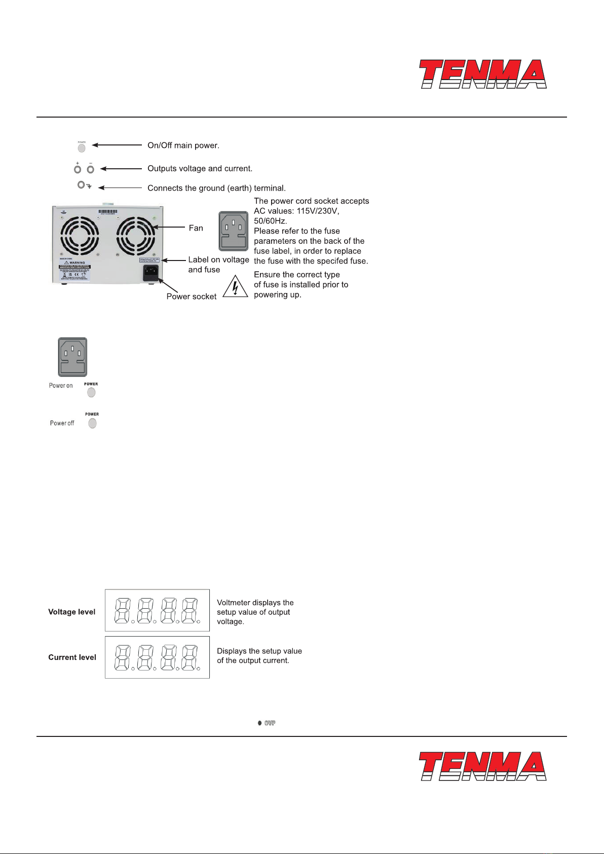
• When the output voltage is higher than the protection setup value, due to unexpected conditions, the output cuts o and
the OVP indicator ickers.
• Press the OVP key again and the power supply will recover.
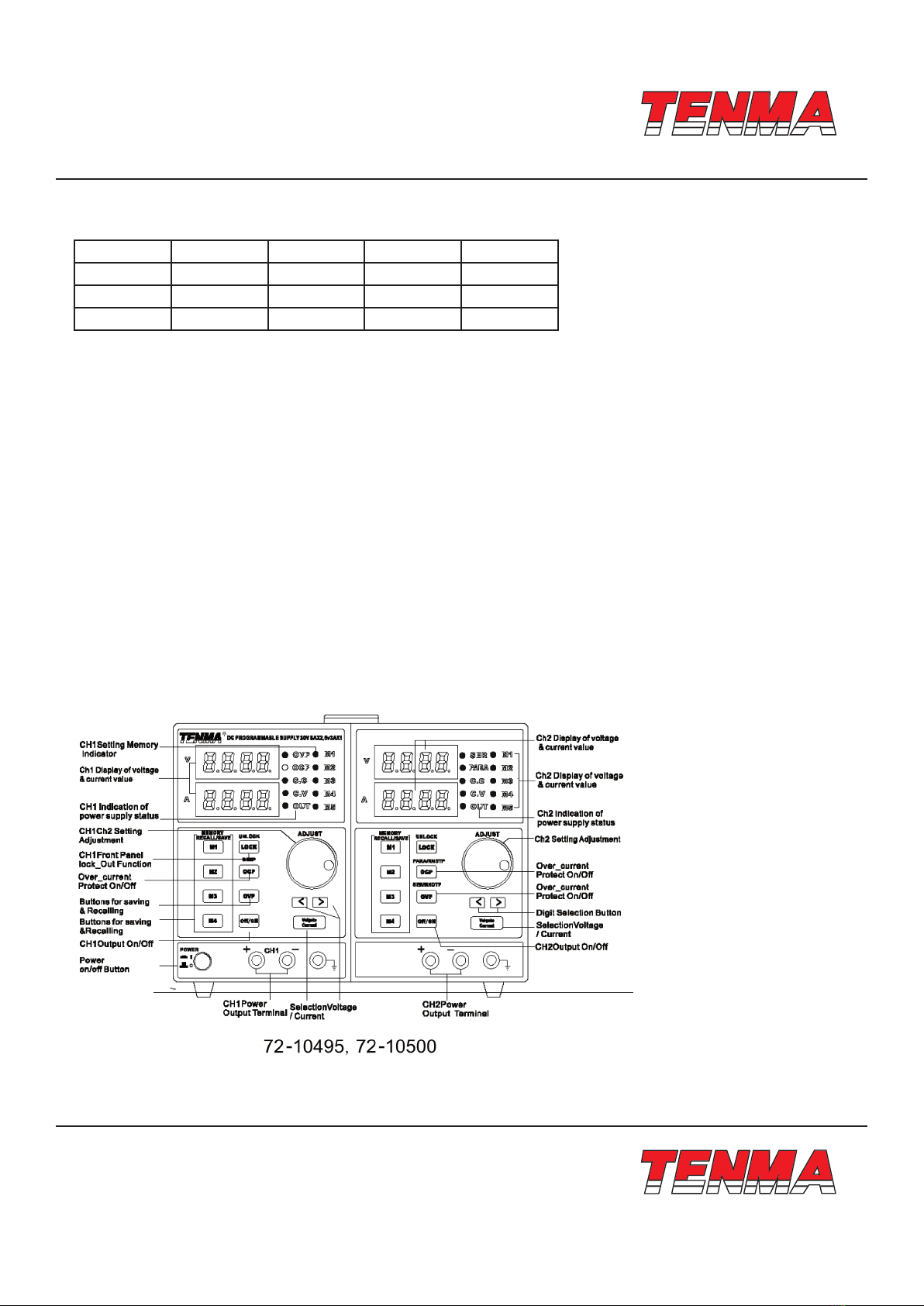
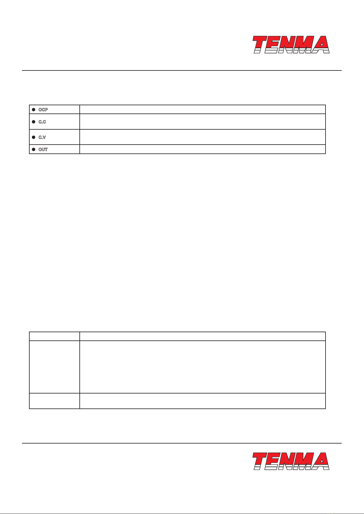
OCP is OCP indicator. When overcurrent function is turned on, the OCP indicator light turns on.
C.C is the constant current indicator. When the power supply is in the mode of constant current,
the light will be on.
C.V is the constant voltage indicator. When the power supply is in the mode of constant voltage,
the light will be on.
OUT is output indicator. If the light is on then there is a voltage output in the output terminal.
Beep ON/OFF
By default, the beep sound is enabled.
To tum o the beep, press the OCP (BEEP) key for two seconds.
A beep sounds, meaning the beep setting will be turned o.
To enable the beep, press the OCP (BEEP) key for two seconds again.
Front Panel Lock
Press the LOCK key to lock the front panel key operation. The key LED will tum on.
To unlock, press and hold the LOCK key for two seconds.
Output Setup
Panel Operation
• Connect the load to the front port, CH1 +/-.
• Press the Voltage/Current key to switch between the voltage adjustment and current adjustment. Adjust the voltage and
current with the Voltage/Current adjustment knob.
• By default, the voltage and current knob work in coarse mode. In order to activate in ne mode, press the key to choose
between coarse or ne mode.
• Turning on the output and pressing the output key will turn on the key LED and display CV or CC mode.
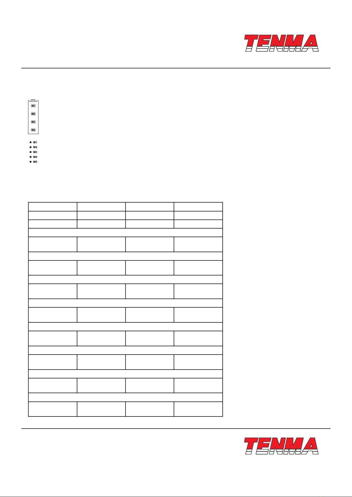
Save Setup
Background The front panel settings can be stored into one of the four internal memories.
Contents
The following list shows the setup contents:
• Fine/coarse knob editing mode
• Beep on/o
• Output voltage/current level
The following settings are always saved as “o”:
• Output on/o
• Front panel lock on/o
Panel Operation Press one of the four buttons (M 1, M2, M3, M4) and the LED light turns on accordingly. After
adjusting the value, it is automatically saved, once the LED light stops blinking.

TM
TM
Page <7> V1.028/12/21
Newark.com/exclusive-brands
Farnell.com/exclusive-brands
Element14.com/exclusive-brands
Recall Setup
The front panel settings can be recalled from one of the four internal memories.
Press any button of M1 to M4.
For example, the memory of the panel setting is recalled in M1.
After you recall M4, rotate the shuttle knob and then M5 is recalled.
If the memory indicator is lit on the panel of lights, then the current memory is recalled.
Note: When a setting is recalled the output automatically turns o.
Specications
Note: The specications in the table below have all been tested in temperatures ranging from 25°C down to -5°C, and after
being warmed up for 20 minutes.
Part Number 72-10495 72-10500 72-10505
Voltage Range 0-30V 0-30V 0-30V
Current Range 0-5A 0-3A 0-3A
Load Regulation
Voltage
Current
≤0.1%+5mV
≤0.1%+10mA
≤0.01%+3mV
≤0.1%+5mA
≤0.01%+3mV
≤0.1 %+5mA
Line Regulation
Voltage
Current
≤0.01%+3mV
≤0.1%+3mA
≤0.01%+3mV
≤0.1%+3mA
≤0.01%+3mV
≤0.1%+3mA
Setup Resolution
Voltage
Current
10mV
1mA
10mV
1mA
10mV
1mA
Setup Accuracy (25°C to -5°C)
Voltage
Current
≤0.5%+20mV
≤0.5%+10mA
≤0.5%+20mV
≤0.5%+5mA
≤0.5%+30mV
≤0.5%+5mA
Ripple (20-20m)
Voltage
Current
≤2mVrms
≤3mArms
≤1mVrms
≤3mArms
≤1mVrms
≤3mVrms
Temperature Coecient
Voltage
Current
≤150ppm
≤150ppm
≤150ppm
≤150ppm
≤150ppm
≤150ppm
Read Back Accuracy
Voltage
Current
10mV
1mA
10mV
1mA
10mV
1mA
Read Back Temperature Coecient
Voltage
Current
≤150ppm
≤150ppm
≤150ppm
≤150ppm
≤150ppm
≤150ppm

TM
TM
Page <8> V1.028/12/21
Newark.com/exclusive-brands
Farnell.com/exclusive-brands
Element14.com/exclusive-brands
Important Notice : This data sheet and its contents (the “Information”) belong to the members of the AVNET group of companies (the “Group”) or are licensed to it. No licence is granted for
the use of it other than for information purposes in connection with the products to which it relates. No licence of any intellectual property rights is granted. The Information is subject to change
without notice and replaces all data sheets previously supplied. The Information supplied is believed to be accurate but the Group assumes no responsibility for its accuracy or completeness,
any error in or omission from it or for any use made of it. Users of this data sheet should check for themselves the Information and the suitability of the products for their purpose and not make
any assumptions based on information included or omitted. Liability for loss or damage resulting from any reliance on the Information or use of it (including liability resulting from negligence or
where the Group was aware of the possibility of such loss or damage arising) is excluded. This will not operate to limit or restrict the Group’s liability for death or personal injury resulting from its
negligence. TENMA is the registered trademark of Premier Farnell Limited 2019.
Part Number 72-10495 72-10500 72-10505
Reaction Time
Voltage Rise
Voltage Drop
≤100mS
≤100mS
(10% rated load)
≤100mS
≤100mS
(10% rated load)
≤100mS
≤100mS
(10% rated load)
Interface: Interfaces (for programmable models only): RS232, USB
Accessories: User manual and power cord
Part Number Dimensions Weight
72-10495 220×156×260mm 9.1kg
72-10500 220×156×260mm 6.5kg
72-10505 220×156×260mm 6.7kg
INFORMATION ON WASTE DISPOSAL FOR CONSUMERS OF ELECTRICAL & ELECTRONIC EQUIPMENT
When this product has reached the end of its life it must be treated as Waste Electrical & Electronics Equipment (WEEE).
Any WEEE marked products must not be mixed with general household waste, but kept separate for the treatment,
recovery and recycling of the materials used. Contact your local authority for details of recycling schemes in your area.
Made in China. PR2 9PP
Other manuals for TENMA 72-10495
1
This manual suits for next models
2
Table of contents
Other Tenma Power Supply manuals

Tenma
Tenma 72-2685 User manual

Tenma
Tenma 72-8345A User manual

Tenma
Tenma 72-8340A User manual

Tenma
Tenma 72-2660 User manual

Tenma
Tenma 72-13300 User manual

Tenma
Tenma 72-8000 Series User manual

Tenma
Tenma TENMA 72-10495 User manual

Tenma
Tenma 72-6851 User manual

Tenma
Tenma 72-8340 User manual

Tenma
Tenma 72-6854 User manual

Tenma
Tenma 72-7655 User manual

Tenma
Tenma 72-2630 User manual

Tenma
Tenma 72-630 User manual

Tenma
Tenma 72-8690 Series User manual

Tenma
Tenma 72-2685 User manual

Tenma
Tenma 72-13095 User manual

Tenma
Tenma 72-8795 User manual

Tenma
Tenma 72-7675 User manual

Tenma
Tenma 72-2535 User manual

Tenma
Tenma 72-8695A User manual