manuals.online logo
Brands
  1. Home
  2. •
  3. Brands
  4. •
  5. Tenma
  6. •
  7. Power Supply
  8. •
  9. Tenma TENMA 72-10495 User manual

Tenma TENMA 72-10495 User manual

Important notes to avoid damage:
- Do not allow power supply to sink current. (Use diode when charging battery.)
- In series mode, the voltage at the output is the sum of the voltages on the CH1 and CH2
displays
- In parallel mode, the current at the output is the sum of the currents on the CH1 and CH2
displays
- In parallel mode, connect load to CH2 (right hand) channel. (When mains power is turned
on, the power supply defaults to independent mode, and CH1 to whatever voltage and cur-
rent settings are in CH1 memory recall M1, with the load turned off.)
- OCP and OVP do not work in serial and parallel modes.
- For sensitive circuits, disconnect load before:
- Switching load on or off with “OFF/ON” button for that channel
- Switching mains off with the load switched on
Do not leave a load connected to CH2 in SER (serial) mode. If you recall a CH2 memory in
SER mode, only CH2 is updated from that memory and only CH2 turns off. At this time, CH2
output terminals have up to -1.2 V (i.e. reverse polarity) on them, with a short circuit current
of up to -2.8 A.
Important notes to avoid frustration:
- Automatically switches between constant voltage (CV) and constant current (CC) modes
- There is a small +/- voltage and current while the load is switched off (50mV, 100 uA)
- CH2 OUT LED stays on after CH2 OCP/OVP trip disconnects the load.
- CH2 OVP/OCP buttons also control CH1 OVP/OCP
- CH1 OVP/OCP buttons only control CH1 OVP/OCP
- The OCP and OVP LEDs apply to whichever channel last updated them. Pressing either
the OVP or OCP buttons updates both the OVP and OCP LEDs with current state for that
channel.
Edits are in colour, and from an end user who has no affiliation with the supplier or manufac-
turer. No liability is accepted for any information in, or omission from, this document. Your
unit may work differently than described here if it has a different hardware or software ver-
sion.
Use at your own risk
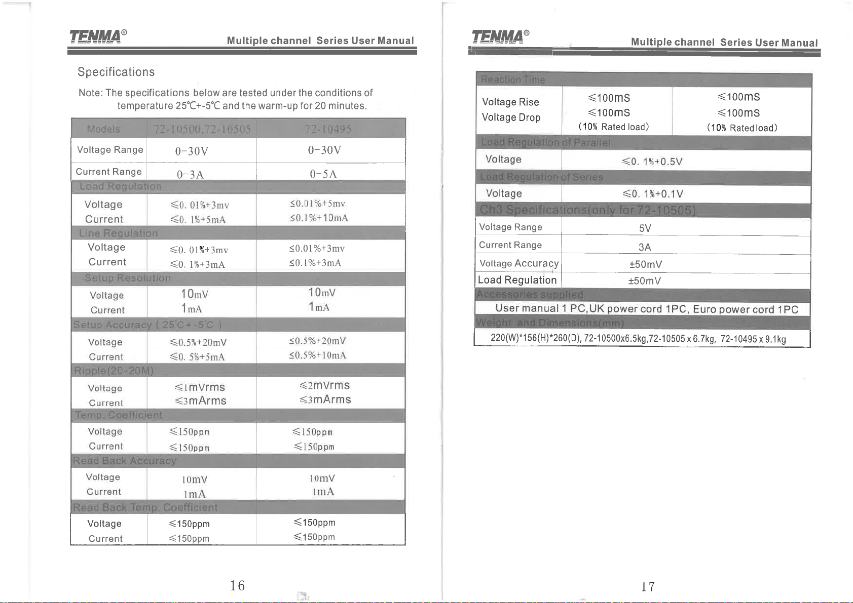
- TENMA 72-10495 (Korad KA3005D-2S): 30V-5A x 2 Channels
- TENMA 72-10500 (Korad KA3003D-2S): 30V-3A x 2 Channels
- TENMA 72-10505 (Korad KA3003D-3S): 30V-3A x 2 Channels & 5V-3A x 1
Velleman supply the single channel version with remote interface as the Velleman LABPS3005D
(which they used to call the PS3005D) The "D" in the Korad model number means no remote in-
terface.
5 pairs
When OCP or OVP trips the output
off:
- A beep is emitted (if beep is en-
abled),
- The OUT and CV/CC LEDs re-
main on for CH2 (but turn off for
CH1)
- The settings values for voltage
and current are displayed (instead of
measured values), as is usual when
the load is off.
The OCP and OVP LEDs
are situated on the CH1
display. However they
are used for displaying
the OCP and OVP state
for both channels. They
display the state of OCP
and OVP for whichever
channel the OCP or OVP
buttons were last
pressed for. Pressing ei-
ther the OCP or OVP
button for a channel will
toggle its state and up-
date both the OCP and
OVP LEDs.
If you press and hold the
OCP/BEEP button for 2
secs to turn beep on/off,
it inadvertently changes
the state of channel 1
OCP. Likewise, pressing
the PARA and SER but-
tons for 2 seconds will in-
advertently change the
state of channel 2 OCP
or OVP when entering in-
dependent mode.
SER
SER
PAR
PAR
Indication of saving and recalling
5 setups stored internally
CH2 OVP/OCP buttons also control
CH1 OVP/OCP
CH1 OVP/OCP buttons only control
CH1 OVP/OCP
See the FAQ sec-
tion for reasons
why OCP may trip
the load off with
small current
loads.
voltage
voltage
The sound of the beep is sometimes a bit er-
ratic. When beep is turned off, some keys may
still occasionally beep. When beep is turned on,
an OCP or OVP trip will make the unit beep
once. If you press and hold the OCP/BEEP
button for 2 secs to turn beep on/off, it inadver-
tently changes the state of the OCP.
Off/On
Off/On
OUT
and the OUT
The sound of the beep is sometimes a bit erratic. When beep is turned off, some keys may still
occasionally beep. When beep is turned on, an OCP or OVP trip will make the unit beep once.
If you press and hold the OCP/BEEP button for 2 secs to turn beep on/off, it inadvertently
changes the state of the OCP.
Pressing the SER/
INDEP button for over 2
secs will also inadver-
tently change the state
of the OCP when exiting
SER mode.
The current at the out-
put is displayed on both
CH1 and CH2 displays.
The voltage at the out-
put is the sum of the
voltages on the CH1
and CH2 displays
SER
PAR
M5
M5
OVP and OCP do not work in series and parallel modes
(even though their LEDs might be on)
When you exit serial or parallel
mode, the CH2 values remain
repeated on the CH1 side and
one memory LED is on for
CH1, but the values on the
CH1 display (while being the
currently used set values for
CH1) are not actually those
stored in that memory.
Terminal
Do not leave a load connected to CH2 in SER (serial) mode. If you recall a CH2
memory in SER mode, only CH2 is updated from that memory and only CH2 turns
off. At this time, CH2 output terminals have up to -1.2 V (i.e. reverse polarity) on
them, with a short circuit current of up to -2.8 A.
Pressing the PARA/
INDEP button for over 2
secs will also inadver-
tently change the state
of OVP when exiting
PARA mode.
The voltage at the out-
put is displayed on both
CH1 and CH2 displays.
The current at the out-
put is the sum of the
currents on the CH1
and CH2 displays
do not work (even though
OVP and OCP LEDs might
be on).
SER
PAR
cannot be changed.
CH2
five
M5
M5
The OCP and OVP enabled
state are not saved with any
memory, and are unaffected by
recalling memories. The OCP
and OVP enabled states are al-
ways set to off when the power
supply is powered up with the
mains switch.
You might consider manually
wiring the channels (in indepen-
dent mode) in series or parallel in-
stead of using the built-in SER and
PARA modes. While there would
be no tracking, you could use OVP
and OCP.
If you press the currently selected memory key you do not have
to wait for it to stop blinking
Voltage setting:
- For use in constant
voltage mode: this is the
desired constant voltage.
- For use in constant
current mode: this is the
desired voltage limit.
- If you enable
overvoltage protection,
the output switches off
automatically if the volt-
age exceeds this value.
Current setting:
- For use in con-
stant voltage mode:
this is the desired
current limit.
- For use in con-
stant current mode:
this is the desired
constant current.
- If you enable
overcurrent protec-
tion, the output
switches off automati-
cally if the current ex-
ceeds this value.
You can change the val-
ues with the output
switch on, in which case:
After about 4 seconds
without you making fur-
ther changes (or immedi-
ately if you press the cur-
rently selected memory
key), the value being
changed is saved to
memory, ceases to flash,
and the display resumes
showing the measured
value at the output.
Since the desired constant voltage is also the voltage OVP limit, OVP cannot
protect you against inadvertently exceeding the OVP limit using the adjust-
ment knob.Since the desired constant current limit is also the OCP limit, OCP
cannot protect you against inadvertently exceeding the OCP limit using the ad-
justment knob.
five
Cause 1: - The output will refuse to turn on if OVP/OCP is on and the voltage or current
present at the output terminals is above the stored set voltage or current values.
Cause 2: - OCP was on and the current setting was too small. (Trip is due to power supply in-
ternal capacitor in-rush current). When using small current settings and OCP:
Start with load turned off and the load disconnected from the power supply output terminals.
Turn OCP off, or use use these minimum current settings: 100 mA at 5V, 200 mA at 12 V,
400mA at 24 V. Turn the power supply output on. Turn on OCP, if if wasn’t already on. Re-
duce the current setting to an appropriate value for the in-rush of your load. Connect the load
to the power supply output terminals. If required, reduce the current setting further, to an ap-
propriate value for the steady-state of your load.
Q5: When I press the OVP or OCP buttons, the OVP and OCP LEDs do not behave as expected.
A5: CH2 OVP/OCP buttons also control CH1 OVP/OCP. CH1 OVP/OCP buttons only control CH1
OVP/OCP. Pressing either the OCP or OVP button for a channel will toggle its state and update both
the OCP and OVP LEDs with the OCP/OVP states associated with that channel. The above facts lead to
some interesting but logical behavior. You have to know what channel last updated those LEDs to know
what channel the LEDs apply to. Another example: The OCP and OVP LEDs might be off, but OCP and
OVP are enabled for CH2. Another example: Pushing the OCP or OVP button will not always change the
state of the OCP or OVP LED. I.e. in the case where the update to the LED from the button you just
pressed is the same state as was previously being displayed for the other channel. Another example:
Pressing the CH2 OCP button can cause the OVP LED to light up. Explanation: If CH1 is currently be-
ing displayed on the OCP and OVP LEDs and they are both off, and CH2 OCP is on and CH2 OVP is on,
then pressing the CH2 OCP button will turn off CH2 OCP, and so the LEDs displayed after that will be:
OVP on, OCP off. (i.e. Pressing the CH2 OCP button caused the OVP LED to light up. This is not
wrong, just confusing if you don't know how it works!)
V/A
12
V
A
3
When C.V. LED lights on, it is
in the mode of zero calibration.
Press the buttonto switch
voltage zero calibration and current
zero calibration. When voltage meter
blink , it is in the mode of voltage zero
calibrationwhile it is in the mode of
current zero calibration if current
meter blinks.
Press and hold the button
“M4”, and thenpress the
button “ POWER ” to swi tch on .
Benchtop multimeter with mV display;
Ammeter with mA display.
When C.C LED lights on, it is in the
mode of amplitude calibration .
Press the buttonto switch
voltage amplitude calibration and
current amplitude calibration.
When voltage meter blinks, it is
in the mode of voltage amplitude
calibrationwhile it is in the mode
of current amplitude calibration if
current meter blinks.
Press the button "M4" again, and then it
is into the mode of amplitude calibration.
Benthtop multimeter with mV display;
Electronic load with mA display and max display current 5A.
Calibration instruments: benchtop multimeter with 6.5 digits
display, & 5A electronic load with mA display.
Calibration condition: Preheat for 2 minutes after switching
on.
Being into calibration mode: press and hold the button “M4”,
and switch on at the same time (see picture 1) until voltage
displays blink. At this time, C.V LED lights on, which means the
power supply is in the mode of zero calibration(see picture 2).
1. Voltage Zero Calibration: connect the positive pole and
Negative pole of the multimeter leads into the output
terminals respectively. Then, watch the voltmeter and adjust
the knob to make the multimeter display in the range 0V-
5mV. After that, the zero calibration is over. Press the button
“M1” to save the calibration value.
2. C u r r e n t Z e r o C a l i b r a t i o n : p r e s s t h e b u t t o n
VOLTAGE/CURRENT, and the current display of the power
supply blinks. Connect amperemeter to adjust the current
value in the range 0mA -1mA. Then press the button “M1” to
save the calibration value.
3. Voltage full-range calibration:adjust voltmeter into the
stall of voltage test. Press the button “M4” again and then
C.C LED lights on, which means now it is in the full-range
calibration. And then the voltage display meter blinks, turn
the knob to adjust the multimeter display in the range
between 30.00V-30.01V. And then press the button “M1” to
save the calibration value.
4. C u r r e n t f u l l - r a n g e c a l i b r a t i o n : p r e s s t h e b u t t o n
VOLTAGE/CURRENT, and then the current display meter
of the power supply blinks, which means it is in the mode of
current calibration. At this time, connect the amperemeter(or
electronic load), and then adjust the current to 5.000A±5mA.
After that, press the button “M1” to save the calibration
value.
5. Switch off, and then restart the power supply. The
calibration ends.
6. As for dual and triple channel power supplies, after channel
1 is calibrated, repeat the procedures above to calibrate
channel 2, the same calibration way as that of channel 1.
Calibration

Other manuals for TENMA 72-10495

1

This manual suits for next models

5

Other Tenma Power Supply manuals

Tenma 72-13300 User manual

Tenma

Tenma 72-13300 User manual

Tenma 72-2630 User manual

Tenma

Tenma 72-2630 User manual

Tenma 72-8345A User manual

Tenma

Tenma 72-8345A User manual

Tenma 72-8355 User manual

Tenma

Tenma 72-8355 User manual

Tenma TENMA 72-10495 User manual

Tenma

Tenma TENMA 72-10495 User manual

Tenma 72-2535 User manual

Tenma

Tenma 72-2535 User manual

Tenma 72-6851 User manual

Tenma

Tenma 72-6851 User manual

Tenma 72-2660 User manual

Tenma

Tenma 72-2660 User manual

Tenma 72-8690 Series User manual

Tenma

Tenma 72-8690 Series User manual

Tenma 72-2685 User manual

Tenma

Tenma 72-2685 User manual

Tenma 72-8795 User manual

Tenma

Tenma 72-8795 User manual

Tenma 72-6854 User manual

Tenma

Tenma 72-6854 User manual

Tenma 72-8340A User manual

Tenma

Tenma 72-8340A User manual

Tenma 72-8000 Series User manual

Tenma

Tenma 72-8000 Series User manual

Tenma 72-2685 User manual

Tenma

Tenma 72-2685 User manual

Tenma 72-630 User manual

Tenma

Tenma 72-630 User manual

Tenma 72-7675 User manual

Tenma

Tenma 72-7675 User manual

Tenma 72-8695A User manual

Tenma

Tenma 72-8695A User manual

Tenma 72-7655 User manual

Tenma

Tenma 72-7655 User manual

Tenma 72-8340 User manual

Tenma

Tenma 72-8340 User manual

Tenma 72-13095 User manual

Tenma

Tenma 72-13095 User manual

Popular Power Supply manuals by other brands

Assa Abloy Securitron AQL102 quick start guide

Assa Abloy

Assa Abloy Securitron AQL102 quick start guide

Wealtec ELITE 600 Installation and operation manual

Wealtec

Wealtec ELITE 600 Installation and operation manual

GW Instek SPS-1230 user manual

GW Instek

GW Instek SPS-1230 user manual

Rosewill PHOTON 550 user manual

Rosewill

Rosewill PHOTON 550 user manual

Allied Telesis AT-PWR01 installation guide

Allied Telesis

Allied Telesis AT-PWR01 installation guide

Eaton Crouse-Hinds MTL F890 instruction manual

Eaton

Eaton Crouse-Hinds MTL F890 instruction manual

Extreme Networks BlackDiamond 6808 installation guide

Extreme Networks

Extreme Networks BlackDiamond 6808 installation guide

4ms Company Row Power 25 user manual

4ms Company

4ms Company Row Power 25 user manual

Altronix WayPoint562 installation guide

Altronix

Altronix WayPoint562 installation guide

Satel APS-412 manual

Satel

Satel APS-412 manual

Gallagher B80 instructions

Gallagher

Gallagher B80 instructions

Symmetricom SSU-2000e user guide

Symmetricom

Symmetricom SSU-2000e user guide

Kikusui PWX750ML user manual

Kikusui

Kikusui PWX750ML user manual

IBM 1500VA Guide

IBM

IBM 1500VA Guide

Puls SLA3.100 installation manual

Puls

Puls SLA3.100 installation manual

Puls DIMENSION CS Series instruction manual

Puls

Puls DIMENSION CS Series instruction manual

Kikusui PMX-A Series Communication Interface Manual

Kikusui

Kikusui PMX-A Series Communication Interface Manual

Ingenico iCT 200 Series quick start guide

Ingenico

Ingenico iCT 200 Series quick start guide

manuals.online logo
manuals.online logoBrands
  • About & Mission
  • Contact us
  • Privacy Policy
  • Terms and Conditions

Copyright 2025 Manuals.Online. All Rights Reserved.