manuals.online logo
Brands
  1. Home
  2. •
  3. Brands
  4. •
  5. Terex
  6. •
  7. Industrial Equipment
  8. •
  9. Terex C5000 Series User manual

Terex C5000 Series User manual

TEREX UTILITIES TECHNICAL SUPPORT TEAM
PHONE: 1-844-TEREX4U (1-844-837-3948) | EMAIL: [email protected]
MODEL(S): TOOLS NEEDED:SERVICE CALL:
NO.
ADJUSTING SYSTEM RELIEF
PRESSURE C4000, C5000, C6000, GENERAL HYDRAULIC PRESSURE GAUGE
(0-5000 PSI)
9/16” OR 3/4” WRENCH
SET OF STANDARD ALLEN WRENCHES
ADJUSTING SYSTEM RELIEF PRESSURE
02
DANGER
Failure to obey the instructions and safety
rules in the appropriate Operator’s Manual and
Service Manual for your machine will result in
death or serious injury.
Many of the hazards identied in the
Operator’s Manual are also safety hazards
when maintenance and repair procedures are
performed.
DO NOT PERFORM
MAINTENANCE UNLESS:
√You are trained and qualied to perform
maintenance on this machine.
√You read, understand and obey:
•manufacturer’s instructions and safety rules
•employer’s safety rules and worksite
regulations
•applicable governmental regulations
.
√You have the appropriate tools, lifting
equipment and a suitable workshop.
The information contained in this Tech Tip is a
supplement to the Service Manual. Consult the
appropriate Service Manual of your machine for
safety rules and hazards.
PAGE 2 OF 6
TECH TIP 02 | RELEASED 10.07.2020 | VERSION 1.0
©TEREX UTILITIES. ALL RIGHTS RESERVED
Escaping uid under pressure can penetrate skin causing serious injury.
Relieve pressure before disconnecting hydraulic lines. Keep away from
leaks and pin holes. Use a piece of cardboard or paper to search for leaks.
DO NOT use your hand.
TECH TIP 02 | RELEASED 10.07.2020 | VERSION 1.0
STEP 1
Determine gauge installation location:
• Units with HOP: Use port G1 on HOP
manifold
• Units without HOP: Tee gauge in the
control line for lift-up between cylinder and
control valve.
See Figure 1 for Sensing Manifold with a G1
location. P/N 485770.
See Figure 2 and Figure 3 for locations on
where the sensing valve may be found on your
unit. An individual sensing valve may also be
located under the rider seat on the command
post.
INTRODUCTION
When setting system relief, it must be veried
that system pressure is present at the base of
the lift cylinders.
If system pressure is not present or improperly
set, the unit may not be able to lift the
capacities shown on the load chart.
This is the reason why pressure is checked at
the base of the lift cylinders or by hooking into
Hydraulic Overload Protection (HOP).
STEP 2
Install the gauge in the location indicated in Step 1. The boom must be supported by the boom rest
or the lift cylinders must be fully retracted before attempting to install the gauge.
PAGE 3 OF 6
TECH TIP 02 | RELEASED 10.07.2020 | VERSION 1.0
10. DS - Digger shift
11. Lower Pressure Drains
12. PS2 - Overload protection for lift cylinders
13. PS1 - Overload protection for gearbox
14. SH - Shuttle valve
15. PO - Pilot set check valve
16. CV - Check valve.
17. S1 - Solenoid for pressure auger release
18. S2 - Solenoid for digger shift.
Not Shown: RP - Reduced Pressure
FIGURE 1
1. COMP - Rod side of lift cylinders.
2. HOP - To dump cartridges on control valve.
3. Base Lift - To lift cylinder base end.
4. G1 - Gauge Port. Normally plugged.
5. G2 - Gauge Port. Normally plugged.
6. Rot LS - Sensing Line from gearbox.
7. Rot LS - Reduced pressure to gearbox.
8. PAR - Pressure auger release.
9. P - Pressure In.
FIGURE 2
1. Test Port Location
1 1
FIGURE 3
1. Test Port Location
PAGE 4 OF 6
TECH TIP 02 | RELEASED 10.07.2020 | VERSION 1.0
STEP 5
If pressure if not at desired level, locate the
return manifold in the pedestal. See Figure 4
for an image of this manifold.
Adjust clockwise to increase the setting; or
adjust counterclockwise to decrease the
setting. Set the pressure to value listed on the
unit-specic placard.
Figure 5 show a return manifold with the
current style system relief cartridge.
STEP 3
Operate unit to bring hydraulic uid to normal
operating temperature.
STEP 4
Raise the boom to full elevation or attach to a
solid object with the load line. The object must
be heavier than what is indicated on the load
chart.
Set the throttle to the maximum setting and
engage the lift-up control. Verify on the gauge
that the pressure is set to what is shown on the
unit-specic placard.
FIGURE 4
1. System Relief
1
FIGURE 5
1. System Relief
PAGE 5 OF 6
FOR FURTHER ASSISTANCE,
CONTACT THE TEREX UTILITIES TECHNICAL SUPPORT TEAM
PHONE: 1-844-TEREX4U (1-844-837-3948) | EMAIL: [email protected]

Other manuals for C5000 Series

2

This manual suits for next models

3

Other Terex Industrial Equipment manuals

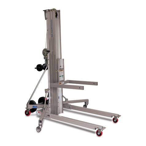
Terex Genie Super Hoist User manual

Terex

Terex Genie Super Hoist User manual

Terex RMX Series User manual

Terex

Terex RMX Series User manual

Terex BID-WELL 2450 User manual

Terex

Terex BID-WELL 2450 User manual

Terex Genie GTH-3007 User manual

Terex

Terex Genie GTH-3007 User manual

Terex Genie Genie Lift User manual

Terex

Terex Genie Genie Lift User manual

Terex RL4000D2 Guide

Terex

Terex RL4000D2 Guide

Terex Genie Superlift Contractor User manual

Terex

Terex Genie Superlift Contractor User manual

Terex Genie Z-45/25J Bi-Energy User manual

Terex

Terex Genie Z-45/25J Bi-Energy User manual

Terex Genie SHOV50014B-1001 User manual

Terex

Terex Genie SHOV50014B-1001 User manual

Popular Industrial Equipment manuals by other brands

AndyMark am-4846 Assembly guide

AndyMark

AndyMark am-4846 Assembly guide

FTI LBOA-10-G Operation, maintenance, and repair manual

FTI

FTI LBOA-10-G Operation, maintenance, and repair manual

ABB HT596318 Operation manual

ABB

ABB HT596318 Operation manual

Siemens 3VL9300-3M.00 manual

Siemens

Siemens 3VL9300-3M.00 manual

BAC PCE Operating and maintenance instructions

BAC

BAC PCE Operating and maintenance instructions

ABB UA16 RA Series operating instructions

ABB

ABB UA16 RA Series operating instructions

PCB Piezotronics 052M96A Installation and operating manual

PCB Piezotronics

PCB Piezotronics 052M96A Installation and operating manual

Modine Manufacturing ElectroFin quick start guide

Modine Manufacturing

Modine Manufacturing ElectroFin quick start guide

FW Murphy LM500 Assembly instructions

FW Murphy

FW Murphy LM500 Assembly instructions

SCHUNK SWS-001 Installation and operating manual

SCHUNK

SCHUNK SWS-001 Installation and operating manual

Blichmann Tower of Power LTE Assembly operation maintenance

Blichmann

Blichmann Tower of Power LTE Assembly operation maintenance

YOKOGAWA SMARTDAC+ user manual

YOKOGAWA

YOKOGAWA SMARTDAC+ user manual

Rohde PW600 instruction manual

Rohde

Rohde PW600 instruction manual

HES HS0753 user manual

HES

HES HS0753 user manual

Endress+Hauser Prothermo NMT 539 operating instructions

Endress+Hauser

Endress+Hauser Prothermo NMT 539 operating instructions

Festo HGPPI Series instructions

Festo

Festo HGPPI Series instructions

ABB Navigator 550 Spares Replacement Procedures

ABB

ABB Navigator 550 Spares Replacement Procedures

Tidland 900 KA Series Operation & maintenance manual

Tidland

Tidland 900 KA Series Operation & maintenance manual

manuals.online logo
manuals.online logoBrands
  • About & Mission
  • Contact us
  • Privacy Policy
  • Terms and Conditions

Copyright 2025 Manuals.Online. All Rights Reserved.