Operator's Manual Supplement First Edition • Second Printing
Installation Instructions
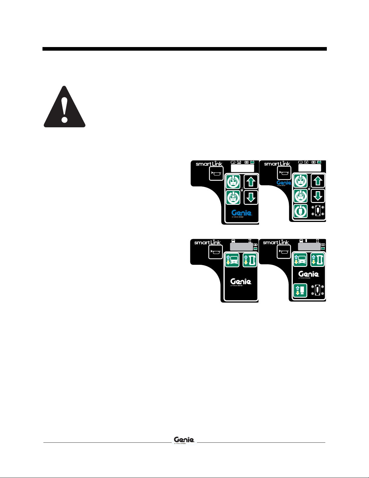
8 Lift Guard™Contact Alarm Part No. 1288739GT
Contents of Kit 1288737GT
GS-1930 / GS-1932 (14.5 inch / 37 cm)
Description Genie part
number Qty.
Cable tie, 7.375 inch / 19 cm 6578GT 40
Button cable tie, 14.75 inch / 37,5 cm 56361GT 8
Cable tie mount, 6.5 inch / 16,5 cm 110149GT 2
Flange nut, 1/4-20, G, ZAG 824027GT 4
Screw, HHF, 1/4-20 x .75, 8, ZAG 824078GT 4
Assembly, lift guard 1287673GT 2
Harness, GS30 platform 1288570GT 1
Cable, 20 inch link 1288572GT 1
Harness, E-STOP splice 1288573GT 1
Cable, 45 inch link 1288574GT 1
Chassis to platform cable 1288726GT 1
Cable guide forming 1290504GT 1
Cable guide forming 1291461GT 1
Manual, Supplement 1288739GT 1
Contents of Kit 1293677GT
GS-1930 / GS-1932 (36 inch / 91 cm)
Description Genie part
number Qty.
Cable tie, 7.375 inch / 19 cm 6578GT 40
Button cable tie, 14.75 inch / 37,5 cm 56361GT 8
Cable tie mount, 6.5 inch / 16,5 cm 110149GT 2
Flange nut, 1/4-20, G, ZAG 824027GT 4
Screw, HHF, 1/4-20 x .75, 8, ZAG 824078GT 4
Harness, GS30 platform 1288570GT 1
Cable, 20 inch link 1288572GT 1
Harness, E-STOP splice 1288573GT 1
Cable, 45 inch link 1288574GT 1
Chassis to platform cable 1288726GT 1
Cable guide forming 1290504GT 1
Cable guide forming 1291461GT 1
Assembly, contact alarm 1292500GT 2
Manual, Supplement 1288739GT 1
Contents of Kit 1288738GT
GS-2032 (14.5 inch / 37 cm)
Description Genie part
number Qty.
Cable tie, 7.375 inch / 19 cm 6578GT 40
Button cable tie, 14.75 inch / 37,5 cm 56361GT 8
Cable tie mount, 6.5 inch / 16,5 cm 110149GT 2
Flange nut, 1/4-20, G, ZAG 824027GT 4
Screw, HHF, 1/4-20 x .75, 8, ZAG 824078GT 4
Assembly, lift guard 1287673GT 2
Cable, 20 inch link 1288572GT 1
Harness, E-STOP splice 1288573GT 1
Cable, 45 inch link 1288574GT 1
Chassis to platform cable 1288727GT 1
Harness, GS32 platform 1288740GT 1
Cable guide forming 1290505GT 1
Cable guide forming 1291462GT 1
Manual, Supplement 1288739GT 1
Contents of Kit 1293678GT
GS-2032 (36 inch / 91 cm)
Description Genie part
number Qty.
Cable tie, 7.375 inch / 19 cm 6578GT 40
Button cable tie, 14.75 inch / 37,5 cm 56361GT 8
Cable tie mount, 6.5 inch / 16,5 cm 110149GT 2
Flange nut, 1/4-20, G, ZAG 824027GT 4
Screw, HHF, 1/4-20 x .75, 8, ZAG 824078GT 4
Cable, 20 inch link 1288572GT 1
Harness, E-STOP splice 1288573GT 1
Cable, 45 inch link 1288574GT 1
Chassis to platform cable 1288727GT 1
Harness, GS32 platform 1288740GT 1
Cable guide forming 1290505GT 1
Cable guide forming 1291462GT 1
Assembly, contact alarm 1292500GT 2
Manual, Supplement 1288739GT 1