TESTO 0554 1111 User manual

Latest generation testo air velocity & IAQ probes with
Bluetooth®handle
Instruction manual
www. .com information@itm.com1.800.561.8187

1 Safety and disposal
3
1
Safety and disposal
About this document
•The instruction manual is an integral part of the instrument.
•Please read this instruction manual through carefully and familiarize yourself
with the product before putting it to use.
•Pay particular attention to the safety instructions and warning advice in
order to prevent injury and damage to the product.
•Keep this documentation to hand so that you can refer to it when
necessary.
•Always use the complete original instruction manual.
•Hand this instruction manual on to any subsequent users of the product.
Security
•Only use the product properly, for its intended purpose, and within the
parameters specified in the technical data. Do not apply any force.
•Dangers may also arise from the systems being measured or the measuring
environment: always comply with the locally valid safety regulations when
carrying out measurements.
•Do not carry out any contact measurements on uninsulated, live parts.
•Do not store the product together with solvents. Do not use any desiccants.
•Only carry out maintenance and repair work on this instrument which is
described in the documentation. Follow the prescribed steps exactly when
doing the work. Use only original spare parts from Testo.
•Temperature information given on probes/sensors relates only to the
measuring range of the sensor technology. Do not expose handles and feed
lines to temperatures in excess of 50°C (122°F), unless they are expressly
authorized for use at higher temperatures.
•Do not operate the instrument if there are signs of damage on the housing
or supply lines.
Batteries
•Improper use of batteries may cause destruction of the batteries, injuries
due to current surges, fire or the escape of chemicals.
•Only use the batteries supplied in accordance with the instructions in the
instruction manual.
•Do not short, take apart or modify batteries.
www. .com information@itm.com1.800.561.8187
2
System description
4
•Do not expose the batteries to heavy impacts, water, fire or temperatures
above +140 °C or below -20 °C.
•Do not store unused batteries in the proximity of metal objects.
•Do not use any leaky or damaged batteries.
•In the event of contact with battery acid: rinse affected areas thoroughly
with water, and if necessary consult a doctor.
Disposal
•Dispose of faulty rechargeable batteries and spent batteries in accordance
with the valid legal specifications.
•At the end of its useful life, deliver the product to the separate collection
point for electric and electronic devices (observe local regulations) or return
the product to Testo for disposal.
2
System description
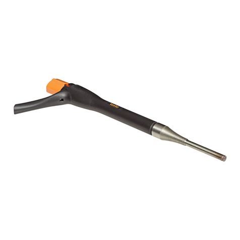
You have acquired a probe with Bluetooth®. This probe comprises a handle, a
probe head and, if applicable, additional probe-specific accessories.
The handle can be connected to all the system’s probe heads and
attachments. The graphic below shows what options the system offers.
You will find detailed information about how each of the probes works
along with the testo 440 measuring instrument in the corresponding
chapter of the instruction manual for the measuring instrument.
www. .com information@itm.com1.800.561.8187

2 System description
5
System overview
1
Bluetooth®handle for
connecting testo 440 probe
heads
(order no. 0554 1111)
2
CO2probe head, including
humidity and temperature sensor
(order no. 0632 1550)
3
High-precision
temperature/humidity probe
head
(order no. 0636 9770)
4
Temperature/humidity probe
head (order no. 0636 9730)
5
CO probe head
(order no. 0632 1270)
6
Handle adapter for connecting
testo 440 flow probes
(order no. 0554 2160)
www. .com information@itm.com1.800.561.8187

3
Description of the instrument
6
7
100 mm vane probe head (order
no. 0635 9430)
8
High-precision 100 mm vane
probe head, including
temperature sensor (order no.
0635 9370)
9
Extendable telescope for
testo 440 flow probes, including
90° angle (order no. 0554 0960)
10
Hot wire probe head, including
temperature and humidity sensor
(order no. 0635 1570)
11
16 mm vane probe head,
including temperature sensor
(order no. 0635 9570)
3
Description of the instrument
3.1
Bluetooth®handle for connecting
testo 440 probe heads (0554 1111)
Application
The handle with Bluetooth®0554 1111 is used for the wireless connection of
probe heads to the testo 440 measuring instrument.
Observe the information on the measuring process in the detailed
instrument instruction manual.
Structure
Element Element
1
Quick-release connector for
probe heads and adapter
2
LED status display
3
Button
4
Battery compartment (on rear)
www. .com information@itm.com1.800.561.8187

3 Description of the instrument
7
Remove battery safety strips
1
Pull safety strips out of the
battery compartment.
3.2
Hot wire probe with Bluetooth®,
including temperature and humidity
sensor (0635 1571)
Use
In conjunction with the testo 440, the hot wire probe is suitable for flow and
humidity measurements in ventilation ducts.
Structure
1
Probe head
2
Probe head connection
3
Telescope
4
Handle adapter
5
Quick-release connector for
probe heads and adapter
6
LED status display
7
Button
8
Bluetooth®handle
9
Battery compartment (on rear)
CAUTION
Damage to sensor possible!
-Do not touch sensor!
-Put the protective sleeve on after the measurement.
www. .com information@itm.com1.800.561.8187

3
Description of the instrument
8
Low flow velocities may result in greater measurement uncertainties
during temperature and humidity measurement. The probe should be
switched on outside a duct under the following conditions:
Ambient temperature: 20°C
Flow: approx. 0 m/s.
Connect hot wire probe to the handle
1
Turn quick-release connector,
viewed from the handle end, through
90° anticlockwise until it locks in
place.
2
Insert handle adapter into the handle
(pay attention to coding).
3
Turn quick-release connector back
through 90° until it locks in place.
4
Insert telescope into the handle
adapter (pay attention to the guide
groove and guide pin).
5
Push telescope in slightly and turn to
lock in place.
6
Push probe head onto the telescope
(pay attention to the guide groove
and guide pin).
7
Push probe head in slightly and turn
to lock in place.
The hot wire probe is ready to use.
www. .com information@itm.com1.800.561.8187
3 Description of the instrument
9
3.3
Vane probe (Ø 16 mm) with Bluetooth®,
including temperature sensor (0635
9571)
Application
In conjunction with the testo 440, the vane probe (Ø 16 mm) is suitable for flow
measurements in ventilation ducts.
Structure
1
Probe head
2
Probe head connection
3
Telescope
4
Handle adapter
5
Quick-release connector for
probe heads and adapter
6
LED status display
7
Button
8
Bluetooth
®
handle
9
Battery compartment (on rear)
CAUTION
Damage to sensor possible!
-Do not touch sensor!
-Put the protective sleeve on after the measurement.
Connect the vane probe (Ø 16 mm) to the handle
1
Turn quick-release connector,
viewed from the handle end, through
90° anticlockwise until it locks in
place.
2
Insert handle adapter into the handle
(pay attention to coding).
3
Turn quick-release connector back
through 90° until it locks in place.
www. .com information@itm.com1.800.561.8187
3
Description of the instrument
10
4
Insert telescope into the handle
adapter (pay attention to the guide
groove and guide pin).
5
Push telescope in slightly and turn to
lock in place.
6
Push probe head onto the telescope
(pay attention to the guide groove
and guide pin).
7
Push probe head in slightly and turn
to lock in place.
The vane probe (Ø 16 mm) is ready to use.
3.4
High-precision vane probe (Ø 100 mm)
with Bluetooth®, including temperature
sensor (0635 9371)
Application
In conjunction with the testo 440, the high-precision vane probe (Ø 100 mm) is
used for flow measurement, e.g. at ventilation outlets.
Structure
1
Probe head
2
Handle adapter
3
Quick-release connector for
probe heads and adapter
4
LED status display
5
Button
6
Bluetooth
®
handle
7
Battery compartment (on rear)
www. .com information@itm.com1.800.561.8187
3 Description of the instrument
11
CAUTION
Damage to sensor possible!
-Do not touch sensor!
The testovent bracket included in the package is intended for the
testovent 417 measurement funnel.
Connect high-precision vane probe (Ø 100 mm) to the handle
1
Turn quick-release connector, viewed
from the handle end, through 90°
anticlockwise until it locks in place.
2
Insert handle adapter into the handle
(pay attention to coding).
3
Turn quick-release connector back
through 90° until it locks in place.
4
Insert probe head into the handle
adapter (pay attention to the guide
groove and guide pin).
5
Push probe head in slightly and turn
to lock in place.
The high-precision vane probe is ready to use.
If necessary, the telescope (order no. 0554 0960) and the 90° angle
(order no. 0554 0991) can be connected, e.g. for measurements at
ceiling outlets.
www. .com information@itm.com1.800.561.8187

3
Description of the instrument
12
3.5
Vane probe (Ø 100 mm) with Bluetooth®,
including temperature sensor (0635
9431)
Application
In conjunction with the testo 440, the vane probe (Ø 100 mm) is used for flow
measurement, e.g. at ventilation outlets.
Structure
1
Probe head
2
Handle adapter
3
Quick-release connector for
probe heads and adapter
4
LED status display
5
Button
6
Bluetooth
®
handle
7
Battery compartment (on rear)
CAUTION
Damage to sensor possible!
-Do not touch sensor!
The testovent bracket included in the package is intended for the
testovent 417 measurement funnel.
Connect vane probe (Ø 100 mm) to the handle
1
Turn quick-release connector,
viewed from the handle end, through
90° anticlockwise until it locks in
place.
2
Insert handle adapter into the handle
(pay attention to coding).
www. .com information@itm.com1.800.561.8187

3 Description of the instrument
13
3
Turn quick-release connector back
through 90° until it locks in place.
4
Insert probe head into the handle
adapter (pay attention to the guide
groove and guide pin).
5
Push probe head in slightly and turn
to lock in place.
The vane probe is ready to use.
If necessary, the telescope (order no. 0554 0960) and the 90° angle
(order no. 0554 0991) can be connected, e.g. for measurements at
ceiling outlets.
3.6
High-precision temperature/humidity
probe with Bluetooth®(0636 9771)
Application
In conjunction with the testo 440, the high-precision temperature/humidity
probe is used to measure humidity and temperature.
Structure
1
Probe head
2
Quick-release connector
3
LED status display
4
Button
5
Bluetooth
®
handle
6
Battery compartment (on rear)
CAUTION
Damage to sensor possible!
-Do not touch sensor!
www. .com information@itm.com1.800.561.8187

3
Description of the instrument
14
Connect high-precision temperature/humidity probe to the handle
1
Turn quick-release connector,
viewed from the handle end, through
90° anticlockwise until it locks in
place.
2
Insert probe head into the handle
(pay attention to coding).
3
Turn quick-release connector back
through 90° until it locks in place.
The high-precision temperature/humidity probe is ready to use.
3.7
Temperature/humidity probe with
Bluetooth®(0636 9731)
Application
In conjunction with the testo 440, the temperature/humidity probe is used to
measure humidity and temperature.
Structure
1
Probe head
2
Quick-release connector for
probe heads and adapter
3
LED status display
4
Button
5
Bluetooth
©
handle
6
Battery compartment (on rear)
CAUTION
Damage to sensor possible!
-Do not touch sensor!
www. .com information@itm.com1.800.561.8187

3 Description of the instrument
15
Connect temperature/humidity probe to the handle
1
Turn quick-release connector,
viewed from the handle end, through
90° anticlockwise until it locks in
place.
2
Insert probe head into the handle
(pay attention to coding).
3
Turn quick-release connector back
through 90° until it locks in place.
The temperature/humidity probe is ready to use.
3.8
CO2probe with Bluetooth®, including
temperature and humidity sensor (0632
1551)
Application
In conjunction with the testo 440, the CO2probe is used to determine CO2and
to measure humidity and temperature.
Structure
1
Probe head
2
Quick-release connector for
probe heads and adapter
3
LED status display
4
Button
5
Bluetooth
®
handle
6
Battery compartment (on rear)
www. .com information@itm.com1.800.561.8187

3
Description of the instrument
16
CAUTION
•
The probe contains sensitive visual components. Please handle the probe
with care.
•
Strong vibrations alter the factory calibration. Checking of readings in fresh
air 350 to 450 ppm CO2 (urban air up to 700 ppm CO2).
•
Avoid dew on the probe, otherwise long-term stability will be impaired. If
there is dew on the probe, this can lead to higher CO2 readings.
•
If the ambient temperature changes (change of measuring location, e.g.
indoors to outdoors or vice versa), the probe requires an acclimatization
phase of a few minutes.
•
After the instrument is switched on, there is a sensor warm-up phase of
approx. 30 s.
•
The CO2 concentration in the sensor requires approx. 60
s to acclimatize to
the environment. Gently waving the probe reduces the acclimatization time.
•
Keep the probe as far away from your body as possible. This avoids any
influences due to the CO2 content of the air you breathe.
Connect CO2probe to the handle
1
Turn quick-release connector,
viewed from the handle end, through
90° anticlockwise until it locks in
place.
2
Insert probe head into the handle
(pay attention to coding).
3
Turn quick-release connector back
through 90° until it locks in place.
The CO2probe is ready to use.
www. .com information@itm.com1.800.561.8187

3 Description of the instrument
17
3.9
CO probe with Bluetooth®(0632 1271)
Application
In conjunction with the testo 440, the CO probe is used to determine the CO
concentration in the environment.
Structure
1
Probe head
2
Quick-release connector for
probe heads and adapter
3
LED status display
4
Button
5
Bluetooth
®
handle
6
Battery compartment (on rear)
DANGER
Risk of death!
Carbon monoxide is a colourless, odourless and tasteless gas. High
concentrations can cause death.
-Do not use the CO probe as a monitoring instrument for personal safety.
Connect CO probe to the handle
1
Turn quick-release connector,
viewed from the handle end, through
90° anticlockwise until it locks in
place.
2
Insert probe head into the handle
(pay attention to coding).
3
Turn quick-release connector back
through 90° until it locks in place.
The CO probe is ready to use.
www. .com information@itm.com1.800.561.8187

4
Commissioning
18
4
Commissioning
Switching on
1
- Press button on the handle.
The handle is switched on.
Switching off
1
-
Press and hold the button on the handle for three seconds.
The handle is switched off.
LED status display
LED status display Meaning
Flashing red Low battery status
Flashing yellow Measurement probe is switched on and is
searching for a Bluetooth connection, but is
not connected.
Flashing green Measurement probe is switched on and
Bluetooth is connected.
www. .com information@itm.com1.800.561.8187

5 Maintenance
19
5
Maintenance
Replacing the batteries
1
Open the battery compartment:
push lock down and remove cover.
2
Take spent batteries out of the
battery compartment and replace
with new batteries (4 x AA type). Pay
attention to polarity.
3
Put battery cover on and push lock
back up.
Handle is ready to use again.
5.1
Maintaining the probes
5.1.1
Cleaning the instrument
Do not use any aggressive cleaning agents or solvents; instead use
mild household cleaning agents or soapy water.
Always keep the connections clean and free from grease and other
deposits.
Clean the instrument and the connections with a damp cloth and dry them off.
www. .com information@itm.com1.800.561.8187

6
Questions and answers
20
5.1.2
Calibration
The probes are supplied with a factory calibration protocol as
standard.
Recalibration of the probes once every 12 months is recommended in
many applications.
This can be carried out by Testo Industrial Services (TIS) or other
certified service providers with the aid of easy-to-
use service software.
6
Questions and answers
Question Possible cause / solution
LED status display flashes
red
Batteries are almost empty. Change the
batteries.
The probe switches itself off Remaining battery capacity is too low. Change
the batteries.
www. .com information@itm.com1.800.561.8187

7 Technical data
21
7
Technical data
•Adjustment conditions for flow probes:
Adjustment in free jet Ø 350 mm, reference pressure 1013 hPa,
based on testo reference Laser Doppler Anemometer (LDA).
•Note for flow probes:
Low flow velocities may result in greater measurement
uncertainties during humidity and temperature measurement!
•Note for humidity probes:
Please do not use the humidity probes in condensing atmospheres.
For continuous use in high-humidity ranges
> 80% RH at ≤ 30°C for > 12 h
> 60% RH at > 30°C for > 12 h
please get in touch with Testo Service or contact us via the Testo
website.
Bluetooth®handle for connecting testo 440 probe heads (0554 1111)
Technical data
Feature Value
Storage temperature
-10°C to +50°C
Operating temperature
0 to +50°C
Dimensions 170 mm x 50 mm x 40 mm
Warranty Duration: 2 years
Hot wire probe with Bluetooth®, including temperature and humidity sensor
(0635 1571)
Feature Value
Measuring range 0 to +50 m/s
-20 to +70°C
5 to 95% RH
700 to 1100 hPa
Accuracy
(at 22°C, ±1 digit)
±(0.03 m/s + 4% of m.v.) (0 to 20 m/s)
±(0.5 m/s + 5% of m.v.) (20.01 to 30 m/s)
±0.8°C (-20 to 0°C)
±0.5°C (0 to +70°C)
±3 hPa
www. .com information@itm.com1.800.561.8187
This manual suits for next models
8
Table of contents
Other TESTO Analytical Instrument manuals
Popular Analytical Instrument manuals by other brands

GREEN INSTRUMENTS
GREEN INSTRUMENTS G26 instruction manual

General
General DCS200 user manual

Vividia
Vividia Ablescope VA-400i manual

PCE Instruments
PCE Instruments PCE-LRF 600 user manual

RS Technical Services
RS Technical Services DD LITE 2 Operation manual

PCE Instruments
PCE Instruments PCE-VE 3 N Series manual

Runpotec
Runpotec Runpocam RC2 instruction manual

Lifa Air
Lifa Air Duct Control Mini Operating and maintenance manual

Toya
Toya Vorel 81791 Operating instruction

KERN
KERN ABS-N Series Operating instruction

Westfalia
Westfalia Wetekom 82 88 41 instruction manual

Powerfix Profi
Powerfix Profi PEK 2.3 A2 Operating instructions and safety instructions