Texas Automation Products DES-43 User manual

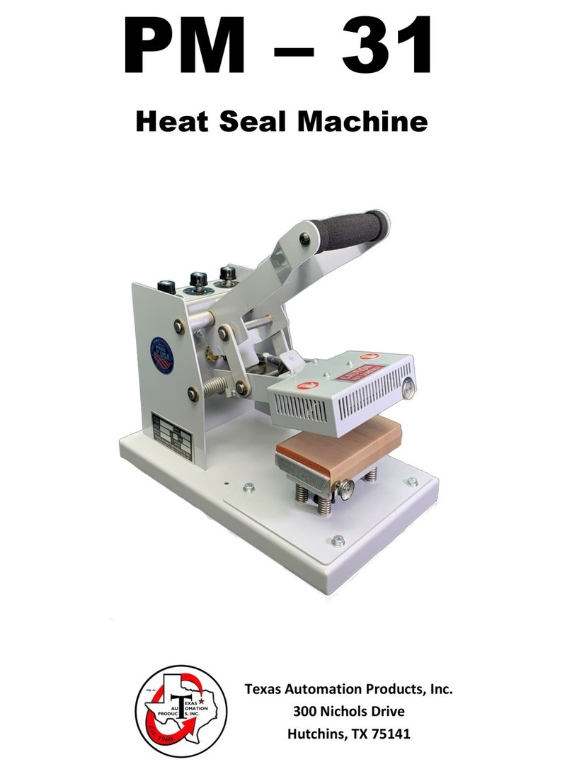
Heat Seal Machine
DES –43
Texas Automation Products, Inc.
300 Nichols Drive
Hutchins, TX 75141

1
CONTENTS
About This Manual......................................................................................................2
Replacement Parts and Technical Assistance ...............................................................2
Chapter 1: Introduction to the DES-43 Pneumatic Heat Seal Machine ..........................3
Chapter 2: Installing the DES-43 ..................................................................................5
Unpacking and Inspecting the DES-43 ......................................................................... 5
Locating and Securing the DES-43................................................................................ 5
Electrical and Compressed Air Requirements.............................................................. 5
Power Consumption..................................................................................................... 6
Connecting the Electrical Power Supply ...................................................................... 6
Connecting Compressed Air ......................................................................................... 6
Setting or Adjusting the Air Line Pressure ................................................................... 7
Turning on Power to the DES-43.................................................................................. 8
Chapter 3: General Operating Principles......................................................................9
General Heat Sealing Principles ................................................................................... 9
Actuating the Heat Seal Machine................................................................................. 9
Using the Emergency Release Pushbutton .................................................................. 9
Chapter 4: Using the DES-43 Control Panel ................................................................10
Layout of the Control Panel ....................................................................................... 10
Start-up and Monitoring Mode.................................................................................. 11
Chapter 5: Setting Cycle Dwell Time ..........................................................................14
Chapter 6: Setting Top Platen Temperature...............................................................15
Chapter 7: Setting Bottom Left Platen Temperature ..................................................16
Chapter 8: Setting Bottom Right Platen Temperature ................................................17
Chapter 9: Setting Air Line Pressure (PSI) Lockout Range ...........................................18
Chapter 10: Cycle Count ............................................................................................19
Resetting Cycle Count ................................................................................................ 20
Chapter 11: Setting a Control Lockout Sequence........................................................21

©1995 Texas Automation Products, Inc. All rights reserved. Printed in U.S.A.
Revision 06022021 2
About This Manual
This manual contains information on how to install and program the DES-43 pneumatic heat
seal machine. It provides an overview of the machine, an explanation of the control panel, and
step-by-step instructions to operate the DES-43.
Replacement Parts and Technical Assistance
For replacement parts or technical assistance, please contact:
Texas Automation Products, Inc.
300 Nichols Drive
Hutchins, TX 75141
972-288-5000
800-872-1960
Fax 972-288-6022
info@texasautomationproducts.com
Please have your model and serial number when calling for service.
Warranty
This machine is fully warranted against defects in workmanship and material for 1 year from
the date of purchase. Platen covers are excluded from warranty.

3
Chapter 1: Introduction to the DES-43 Pneumatic Heat Seal Machine
The DES-43 is the most advanced heat sealing machine in the industry. In addition to being
dependable and easy to use, it offers the following features and capabilities:
Power “ON-OFF” Switch.
Intel Microprocessor based system controls and monitors all machine functions.
User friendly illuminated pushbutton inputs for setting of machine functions. Large red
LED display can be easily read up to 30 feet away and the readout has a rotating
sequence to display the time, temperature, and pressure settings.
Three conveniently located “Start Cycle” pushbuttons, one located on the front handle
and one located on each side of the machine. (To initiate cycle, the start button on the
handle must be depressed simultaneously with either one of the start buttons located
on the sides.)
Oversized “Emergency Release” pushbutton is located on each side of the machine. If
either one is actuated, press will immediately open.
Machine will cycle ONLY when top platen is in position directly over a bottom platen.
Top head swivels smoothly on two frictionless sealed bearings that are permanently
lubricated.
Dual Cycle Timer is programmable in ½ second increments. After the machine is
actuated, the timer counts down until the cycle is completed allowing the operator to
monitor the status of cycle at any time.
Built in resettable cycle counter displays cycle count up to 3999 and counts completed
and in-completed cycles independently on both cycle times. This discourages the
practice of operator short cycling, a major cause of tape adhesion failure.
Top and bottom platen temperatures are adjustable from 100° to 450° Fahrenheit. Top
or bottom platen temperature can be turned “OFF” individually if desired.
Air Regulator / Filter / Gauge Assembly attached to machine.
Air Pressure adjustable from 25 to 120 psi. Total platen pressure is approximately 707
lbs. at 100 psi line pressure.
The Air Cylinder has a ¾” diameter piston rod and the Guide Bar is made of ½” diameter
steel and glides through a DU bearing. Both assure long life, rigidity, and platen
alignment.
Control Lockout feature prevents unauthorized personnel from tampering with machine
settings.
Parameter Lockout feature prevents operator from cycling machine if temperature or
pressure varies more than +/- 10 from their set point.
Slide on Platen Covers for quick change from sponge pad or teflon surface.
Electrical Fuse mounted on circuit board inside machine.

4
Rigidly built for minimal press “breathing”.
Spacious throat area allows for easy handling of large or bulky items.
Many self-diagnostic features are incorporated into the machine control system to help
locate malfunctions if they should occur.
Easy to maintain and operate.
Industrial laundries, uniform rental plants, garment manufacturers, hospitals, nursing homes,
and sportswear manufacturers use the DES-43 to apply the following types of heat seal
materials:
Label tapes
Emblems
Appliques
Ink transfers
Patches
Embroideries
Barcode labels
Flock appliques
Mending tapes
Interfaces
Pressure-sensitive
materials
Heat-sensitive
materials

5
Chapter 2: Installing the DES-43
This chapter provides instructions to help you unpack the DES-43, check that you have all the
components, and make the hardware connections. Perform the installation procedures in the
order in which this chapter presents them.
Unpacking and Inspecting the DES-43
To remove the DES-43 from the shipping crate, you need the following tools:
A knife or suitable sharp instrument
A ½” socket wrench or suitable tool
Cut the cardboard box where it joins the skid. With the socket wrench or other suitable tool,
remove the three bolts that secure the DES-43 to the skid. Carefully lift the DES-43 from the skid
and remove all other materials from the shipping crate.
You should have all of the following items:
The DES-43 pneumatic heat seal machine
The package in which you found this operations manual
Locating and Securing the DES-43
Before connecting power and air, locate the DES-43 heat seal machine where it will be operated.
Choose a location that provides the electrical and compressed air requirements. Bolt base of
machine securely in desired place and position.
Electrical and Compressed Air Requirements
120 volt, 60 Hertz power supply
Air –25 PSI minimum / 120 PSI maximum, .025 Cu. Ft. free air per cycle

6
Power Consumption
PLATEN SIZE
WATTS
AMPS
2” x 4”
900
7.5
3” x 5”
1200
10
4” x 6”
1320
11
5” x 6”
1800
15
3 ¼” x 5” Extended
Anvil
660
5.5
Connecting the Electrical Power Supply
Before connecting electrical power to the DES-43, push the DES-43’s toggle power switch down to
the “OFF” position. Plug the DES-43’s power cord into an appropriate power source, such as a
standard receptacle. The electrical power cord has a molded 15 amp plug.
Connecting Compressed Air
To connect the air supply to the DES-43, perform the following:
Remove the 1/8” male NPT pipe plug from the air line connector located in the back at the
base of the machine. This plug will protect against contaminants entering the air system.
After removing the plug, connect the air supply to the 1/8” female NPT air line connector.

7
Setting or Adjusting the Air Line Pressure
To set or adjust the air line pressure, locate the Air Regulator on the right side of the swivel head.
The required gauge pressure must be in the range of 25 PSI minimum / 120 PSI maximum. To
adjust the regulator, pull up and turn black knob. Clockwise increases pressure; counter-clockwise
decreases pressure. When pressure is set, push down black knob to lock. The following table
converts gauge pressure to total inter-platen pressure and pounds of pressure per square inch on
platen surface.
CONVERSION TABLE
GAUGE
PRESSURE
TOTAL INTER-
PLATEN
PRESSURE
LBS. PSI 2” x
4” PLATEN
LBS. PSI 3” x
5” PLATEN
LBS. PSI 4” x
6” PLATEN
LBS. PSI 5” x
6” PLATEN
LBS. PSI 3 ¼” x
5” EXTENDED
ANVIL PLATEN
25
177
22.1
11.8
7.4
5.9
10.9
30
212
26.5
14.1
8.8
7.1
13.0
35
247
30.9
16.5
10.3
8.2
15.2
40
283
35.4
18.9
11.8
9.4
17.4
45
318
39.8
21.2
13.2
10.6
19.6
50
353
44.1
23.5
14.7
11.8
21.7
55
389
48.6
25.9
16.2
13.0
23.9
60
424
53.0
28.3
17.7
14.1
26.1
65
459
57.4
30.6
19.1
15.3
28.2
70
495
61.9
33.0
20.6
16.5
30.5
75
530
66.2
35.3
22.1
17.7
32.6
80
565
70.6
37.7
23.5
18.8
34.8
85
601
75.1
40.1
25.0
20.0
37.0
90
636
79.5
42.4
26.5
21.2
39.1
95
672
84.0
44.8
28.0
22.4
41.4
100
707
88.4
47.1
29.5
23.6
43.5
105
742
92.7
49.5
30.9
24.7
45.7
110
778
97.2
51.9
32.4
25.9
47.9
115
813
101.6
54.2
33.9
27.1
50.0
120
848
106.0
56.5
35.3
28.3
52.2

8
Turning on Power to the DES-43
Before turning on power, read the rest of this chapter carefully to learn how to make the
necessary adjustments and avoid potential problems. We recommend that you read this entire
manual to become familiar with its contents before operating the DES-43.
To turn on the DES-43, perform the following:
Push the toggle power switch up to the “ON” position.
Wait about two seconds for the DES-43 to adjust. After the unit’s circuits settle, the control panel
displays the version of central processing unit (CPU) software and enters Monitoring mode. For a
complete explanation of Monitoring mode and the controls, see Chapter 4, Using the DES-43
Control Panel.
Caution: If you press the Control Lockout button while the control panel is in Monitoring mode, it
will enter Set Lockout mode. In Set Lockout mode, you can select a three-button
sequence as a code to prevent unauthorized personnel from changing the parameters.
Immediately press Control Lockout again to exit this mode. See Chapter 11, Setting a
Control Lockout Code, for more information.

9
Chapter 3: General Operating Principles
Before you start using the DES-43 pneumatic heat seal machine, read this chapter to become
familiar with general principles of all heat sealing operations and to learn the following operating
procedures that are specific to the DES-43.
Actuating the DES-43
Using the Emergency Release pushbutton
General Heat Sealing Principles
All heat sealing processes involve three main factors, as follows:
The temperature of the platens;
The inter-platen pressure;
The cycle dwell time.
To set tolerances and control values for platen temperature, inter-platen pressure, and cycle dwell
time, use the DES-43 control panel. For more information, see Chapter 4, Using the DES-43
Control Panel. You can also use the control panel’s digital display area to monitor the actual
platen temperatures and air line pressure. The exact settings of the three main factors depend on
the requirements of your specific fusing or transfer application.
Actuating the Heat Seal Machine
To actuate the DES-43:
Position top platen over one of the bottom platens and depress the black pushbutton
labeled “Start Cycle” located on the handle simultaneously with one of the black
pushbuttons labeled “Start Cycle” located on either side of the swivel head. Machine will
cycle ONLY when the top platen is in position directly over a bottom platen.
Using the Emergency Release Pushbutton
To interrupt the DES-43 during operation:
Push one of the red “Emergency Release” pushbuttons located on either side of the swivel
head. This safety feature bypasses the timer and immediately opens the press in case of an
emergency. Only one red pushbutton need be depressed to interrupt cycle. Also, the
press should open immediately if the power switch is turned “OFF”, or if the machine
power cord is unplugged.

10
Chapter 4: Using the DES-43 Control Panel
This section of this manual provides an overview of the control panel for the DES-43 pneumatic
heat seal machine. Before you operate your machine, read this section to learn general
information on using the control panel.
With the control panel, you can set tolerances and control values for platen temperature, inter-
platen pressure, and cycle dwell time. You can also use the control panel’s digital display area to
monitor the DES-43’s actual platen temperatures and air line pressure. The exact settings of the
three main factors depend on the requirements of your specific fusing or transfer application.
Use the Top Temp, Bottom Left Temp and Bottom Right Temp buttons on the control panel to
view and set the platens’ temperatures. Use the Air Line PSI button to view the actual pressure of
the heat seal machine’s pressure regulator and to set a control range. Use the Cycle Time button
in conjunction with either Cycle Time A or Cycle Time B button to set the actuation time and to
view the current time setting.
Layout of the Control Panel
Figure 4-1 shows the DES-43 control panel with all nine control buttons off.
Figure 4-1
DES-43 Control Panel with Buttons Off

11
Start-up and Monitoring Mode
When you first turn on the DES-43, wait about two seconds for it to adjust. After the circuits
settle, the control panel displays the version of CPU software and enters Monitoring mode. In
Monitoring mode, the panel’s numeric display area shows the following values:
The cycle dwell time setting for cycle time A
The current top platen temperature in degrees Fahrenheit
The current bottom left platen temperature in degrees Fahrenheit
The current bottom right platen temperature in degrees Fahrenheit
The current air line pressure
The DES-43’s control panel enters Monitoring mode on initial start-up and when the machine is
idle. While in Monitoring mode, the control panel displays the current cycle dwell time setting for
cycle time A, current top platen temperature, current bottom left platen temperature, current
bottom right platen temperature, and current air line pressure, as shown in Figure 4-2. Because
the control panel displays the platens’ actual temperatures, it shows room temperature for them
when they are not on. If the machine’s pressure regulator is off, the control panel displays zero (0)
for air line pressure.
While the control panel is in Monitoring mode, you can immediately see any function displayed by
pressing and releasing either the Cycle Time A, Cycle Time B, Top Temp, Bottom Left Temp,
Bottom Right Temp, Air Line PSI, or Cycle Count button.
Caution: If you press the Control Lockout button while the control panel is in Monitoring mode, it
will enter Set Lockout mode. In Set Lockout mode, you can select a three-button
sequence as a code that prevents unauthorized personnel from changing the
parameters. Press Control Lockout again to exit this mode. See Chapter 11, Setting a
Control Lockout Sequence, for more information.

12
Cycle Time Setting Current Top Platen Temperature
Current Bottom Left Current Bottom Right Current Air Line
Platen Temperature Platen Temperature Pressure
Figure 4-2
Monitoring Mode (Cycle Time A)

13
Cycle Time Setting Current Top Platen Temperature
Current Bottom Left Current Bottom Right Current Air Line
Platen Temperature Platen Temperature Pressure
Figure 4-3
Monitoring Mode (Cycle Time B)

14
Chapter 5: Setting Cycle Dwell Time
This machine is equipped with a dual timer. After both cycle times are set, the operator can
change the cycle time by pressing either the Cycle Time A or Cycle Time B button. To set the
cycle dwell time, perform the following:
While the control panel is in Monitoring Mode, press and release either Cycle Time A or
Cycle Time B buttons to select the cycle time that you want to set. After selecting either
Cycle Time A or Cycle Time B, press and hold the Cycle Time button. After
approximately two seconds, the panel’s Up Arrow and Down Arrow buttons will light
and the Cycle Time button blinks, as shown in Figure 5-1. This puts the control panel in
the Set Mode. Release the Cycle Time button. The control panel will display the current
setting for the cycle dwell time.
Figure 5-1
Setting Cycle Time
Press either the Up Arrow or the Down Arrow button to change the setting; press and
release to increase or decrease the setting by one increment. To rapidly change the
value, press and hold the appropriate arrow button. Possible cycle dwell time values
range from .5 seconds to 99.5 seconds (in .5 second increments) and from 100 to 999
seconds (in 1 second increments).
After you reach the number of seconds that you want to set as the cycle dwell time,
press and release the Cycle Time button again to save the setting and to return the
control panel to Monitoring Mode.

15
Chapter 6: Setting Top Platen Temperature
To set the temperature of the top platen, perform the following:
While the control panel is in Monitoring Mode, press and hold the Top Temp button.
After approximately two seconds, the panel’s Up Arrow and Down Arrow buttons will
light and the Top Temp button blinks, as show in Figure 6-1. This puts the control
panel in the Set Mode. Release the Top Temp button. The control panel displays the
current setting for the top platen temperature (not the actual temperature, as shown
in Monitoring Mode); if the platen is set to off, the control panel displays three
dashes.
Figure 6-1
Setting Top Platen Temperature
Press either the Up Arrow or the Down Arrow button to change the setting; press and
release to increase or decrease the setting by one (1). To rapidly change the value,
press and hold the appropriate arrow button. Possible top platen temperature values
range from 100° to 450° Fahrenheit. To turn off the top platen, set the value as three
dashes, one above 450° and one below 100°.
After you reach the temperature that you want to set for the top platen, press and
release the Top Temp button again to save the setting and to return the control panel
to Monitoring Mode.

16
Chapter 7: Setting Bottom Left Platen Temperature
To set the temperature of the bottom left platen, perform the following:
While the control panel is in Monitoring Mode, press and hold the Bottom Left Temp
button. After approximately two seconds, the panel’s Up Arrow and Down Arrow
buttons will light and the Bottom Left Temp button blinks, as shown in Figure 7-1. This
puts the control panel in the Set Mode. Release the Bottom Left Temp button. The
control panel displays the current setting for the bottom left platen temperature (not
the actual temperature, as shown in Monitoring Mode); if the platen is set to off, the
control panel displays three dashes.
Figure 7-1
Setting Bottom Left Platen Temperature
Press either the Up Arrow or the Down Arrow button to change the setting; press and
release to increase or decrease the setting by one (1). To rapidly change the value,
press and hold the appropriate arrow button. Possible bottom left platen temperature
values range from 100° to 450° Fahrenheit. To turn off the bottom left platen, set the
value as three dashes, one above 450° and one below 100°.
After you reach the temperature that you want to set for the bottom left platen, press
and release the Bottom Left Temp button again to save the setting and to return the
control panel to Monitoring Mode.

17
Chapter 8: Setting Bottom Right Platen Temperature
To set the temperature of the bottom right platen, perform the following:
While the control panel is in Monitoring Mode, press and hold the Bottom Right Temp
button. After approximately two seconds, the panel’s Up Arrow and Down Arrow
buttons will light and the Bottom Right Temp button blinks, as shown in Figure 8-1. This
puts the control panel in the Set Mode. Release the Bottom Right Temp button. The
control panel displays the current setting for the bottom right platen temperature (not
the actual temperature, as shown in Monitoring Mode); if the platen is set to off, the
control panel displays three dashes.
Figure 8-1
Setting Bottom Right Platen Temperature
Press either the Up Arrow or the Down Arrow button to change the setting; press and
release to increase or decrease the setting by one (1). To rapidly change the value,
press and hold the appropriate arrow button. Possible bottom right platen temperature
values range from 100° to 450° Fahrenheit. To turn off the bottom right platen, set the
value as three dashes, one above 450° and one below 100°.
After you reach the temperature that you want to set for the bottom right platen, press
and release the Bottom Right Temp button again to save the setting and to return the
control panel to Monitoring Mode.

18
Chapter 9: Setting Air Line Pressure (PSI) Lockout Range
You cannot use the control panel to set the heat press device’s actual air line pressure (see
Chapter 2: Setting or Adjusting the Air Line Pressure). You must adjust the pressure regulator to
the desired setting. However, you can use the control panel to set a range limit that prevents
the heat seal machine from actuating unless the actual air line pressure is at the set value
(within the tolerance range of either +/- 10 psi). This is preset at Texas Automation Products
during manufacturing. To set the air line pressure lockout value, perform the following:
While the control panel is in Monitoring Mode, press and hold the Air Line PSI button.
After approximately two seconds, the panel’s Up Arrow and Down Arrow buttons will
light and the Air Line PSI button blinks, as shown in Figure 9-1. This puts the control
panel in the Set Mode. Release the Air Line PSI button. The control panel displays the
current pressure lockout setting.
Figure 9-1
Setting Air Line Pressure Lockout
Press either the Up Arrow or the Down Arrow to change the setting; press and release
to increase or decrease the setting by one (1). To rapidly change the value, press the
appropriate arrow key and hold it down. Possible pressure lockout values range from
25 psi to 120 psi.
After you reach the pressure lockout value that you want, press and release the Air Line
PSI button again to save the setting and to return to the control panel Monitoring Mode.

19
Chapter 10: Cycle Count
The control panel’s cycle count feature allows you to accurately track the number of times the
DES-43 has been actuated for the full-cycle dwell time and “short” cycle time on both the cycle
A time and the cycle B time since the cycle count was last reset. Each time you actuate the heat
seal machine for a completed cycle time setting, the control panel adds one (1) to its current
cycle count. If the machine is actuated and it is “short” cycled, it will add one (1) to its current
“short” cycle count. The control panel’s display area can display numbers from 0 to 999, but it
also uses decimal points, as shown in Table 10-1, to indicate cycle count values of 0 to 3999.
VALUE SHOWN ON CONTROL
PANEL
ACTUAL CYCLE COUNT
000 to 999
000 to 999
000. to 999.
1000 to 1999
00.0. to 99.9.
2000 to 2999
0.0.0. to 9.9.9.
3000 to 3999
Table 10-1
Cycle Count Values
To view cycle count and “short” cycle count on cycle time A:
1. Press and release the Cycle Time A button.
2. Press and release the Cycle Count button to view the current full cycle count.
3. To view the current short cycle count, press and hold the cycle count button. After
approximately 2 seconds the button will light. Press and release the
button to view the short cycles.
To view cycle count and “short” cycle count on cycle time B:
1. Press and release the Cycle Time B button.
2. Press and release the Cycle Count button to view the current full cycle count.
3. To view the current short cycle count, press and hold the cycle count button. After
approximately 2 seconds the button will light. Press and release the
button to view the short cycles.
You cannot use the control panel to increase the cycle count value; the count only increases
when the heat seal machine is successfully actuated for the full duration of the cycle dwell
time. You can, however, lower the count by increments of one (to reflect uses that were not
successful for reasons other than insufficient time) or reset the count completely to zero (0); for
assistance, see the procedures in Resetting Cycle Count on the next page.
Table of contents
Other Texas Automation Products Food Saver manuals

