Table of Contents
1 Features............................................................................1
2 Applications..................................................................... 1
3 Description.......................................................................1
4 Revision History.............................................................. 2
5 Description (continued).................................................. 4
6 Device Key Default Settings........................................... 5
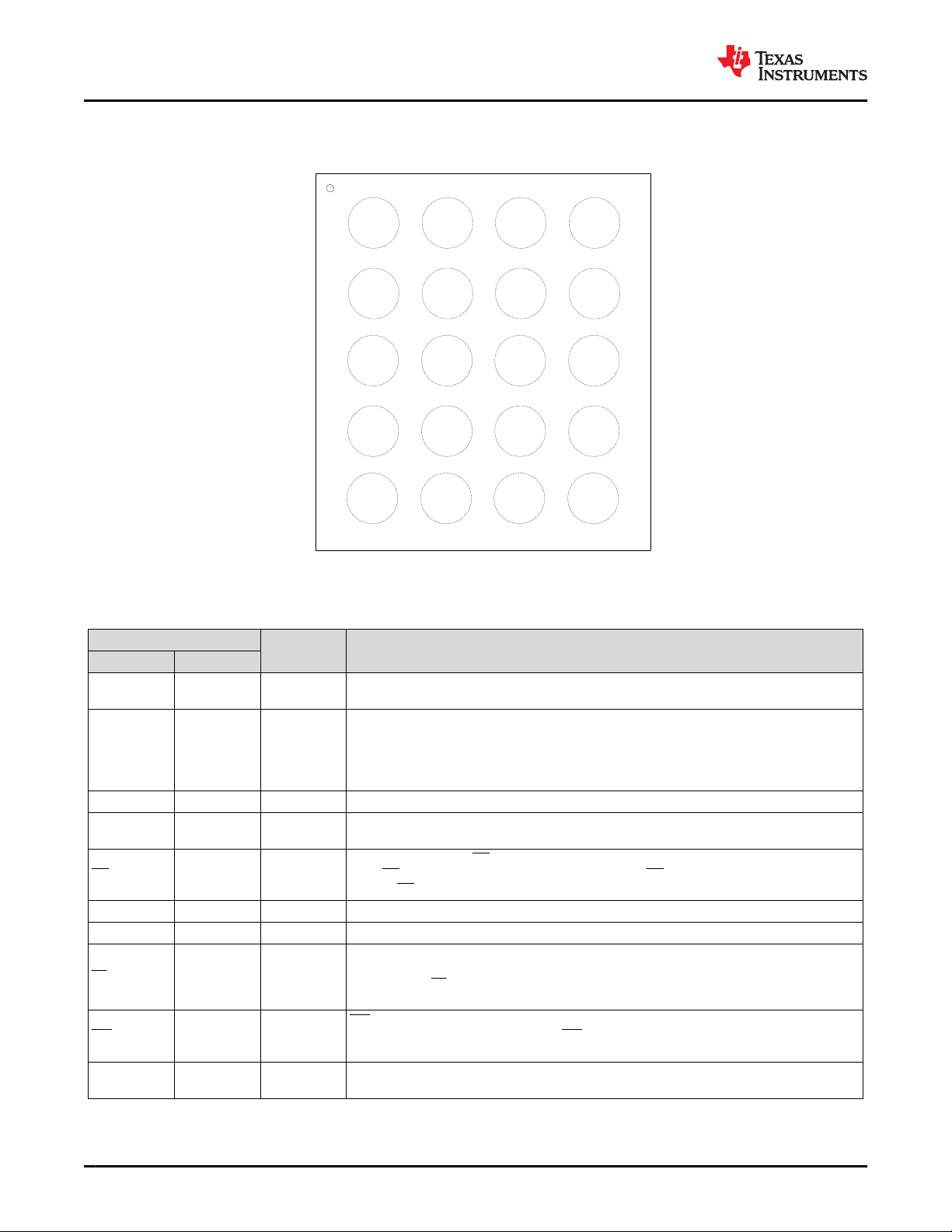
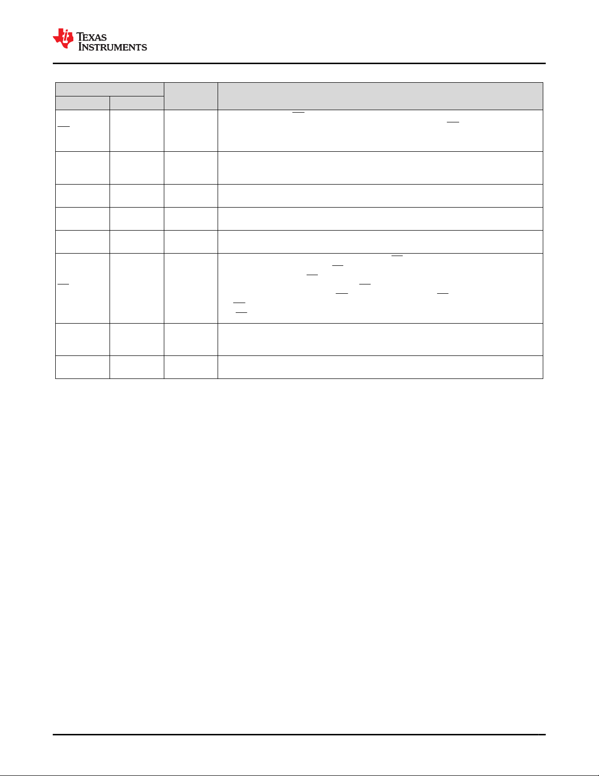
7 Pin Configuration and Functions...................................6
8 Specifications.................................................................. 8
8.1 Absolute Maximum Ratings........................................ 8
8.2 ESD Ratings............................................................... 8
8.3 Recommended Operating Conditions.........................8
8.4 Thermal Information....................................................8
8.5 Electrical Characteristics.............................................9
8.6 Timing Requirements................................................ 12
8.7 Typical Characteristics..............................................14
9 Detailed Description......................................................17
9.1 Overview................................................................... 17
9.2 Functional Block Diagram......................................... 17
9.3 Feature Description...................................................18
9.4 Device Functional Modes..........................................37
9.5 Register Map.............................................................41
10 Application and Implementation................................ 96
10.1 Application Information........................................... 96
10.2 Typical Application.................................................. 96
11 Power Supply Recommendations............................102
12 Layout.........................................................................103
12.1 Layout Guidelines................................................. 103
12.2 Layout Example.................................................... 103
13 Device and Documentation Support........................104
13.1 Device Support..................................................... 104
13.2 Documentation Support........................................ 104
13.3 Receiving Notification of Documentation Updates104
13.4 Support Resources............................................... 104
13.5 Electrostatic Discharge Caution............................104
13.6 Trademarks........................................................... 104
13.7 Glossary................................................................104
14 Mechanical, Packaging, and Orderable
Information.................................................................. 105
4 Revision History
NOTE: Page numbers for previous revisions may differ from page numbers in the current version.
Changes from Revision A (July 2019) to Revision B (August 2023) Page
• Updated the numbering format for tables, figures, and cross-references throughout the document................. 1
• Added Safety-Related Certifications to Features............................................................................................... 1
• Added Device Key Default Settings Table.......................................................................................................... 5
• Added clarification to LP pin description.............................................................................................................6
• Added clarification to ADCIN pin description...................................................................................................... 6
• Added clarification to LS/LDO pin description.................................................................................................... 6
• Changed maximum IPMID in Recommended Operating Conditions....................................................................8
• Changed maximum RON(BAT-PMID) in Electrical Characteristics.......................................................................... 9
• Added footnote in Electrical Characteristics....................................................................................................... 9
• Changed tHW_RESET_WD test conditions and MAX value from 15s to 14s in Timing Requirements.................. 12
• Changed tRESET_WARN parameter..................................................................................................................... 12
• Changed tHW_RESET parameter.........................................................................................................................12
• Changed Input Voltage Based Dynamic Power Management (VINDPM) and Dynamic Power Path
Management (DPPM)section to simplify description........................................................................................ 21
• Added more details to descriptions in ADC Operation When VIN Present.......................................................23
• Changed Load Switch/LDO Output and Control description............................................................................ 25
• Added clarification on LDO voltage programmability........................................................................................25
• Changed tHW_RESET_WARN to tRESET_WARN in Section 9.3.8.2 .......................................................................... 28
• Changed VIN presence to valid VIN presence in Section 9.3.8.2 ................................................................... 28
• Added clarification to TS biasing operation...................................................................................................... 32
• Changed from as well while the VIN input is valid to while the VIN input is valid in Section 9.4.1 .................. 37
• Added link to BQ25155 Setup Guide tool......................................................................................................... 41
• Changed description of IBAT_OCP_ILIM 2b10 setting to "Disable" to describe correct behavior....................41
• Changed clatification to TS_EN bit functionality............................................................................................... 41
• Changed registers 0x42 to 0x4F from R/W-X to R-X in Section 9.5.1 .............................................................41
• Changed Figure 10-3 .......................................................................................................................................98
• Added TS Biasing Figure..................................................................................................................................98
• Added VINLS bypass capacitor layout guideline............................................................................................103
BQ25155
SLUSDO1B – JUNE 2019 – REVISED AUGUST 2023 www.ti.com
2Submit Document Feedback Copyright © 2023 Texas Instruments Incorporated
Product Folder Links: BQ25155