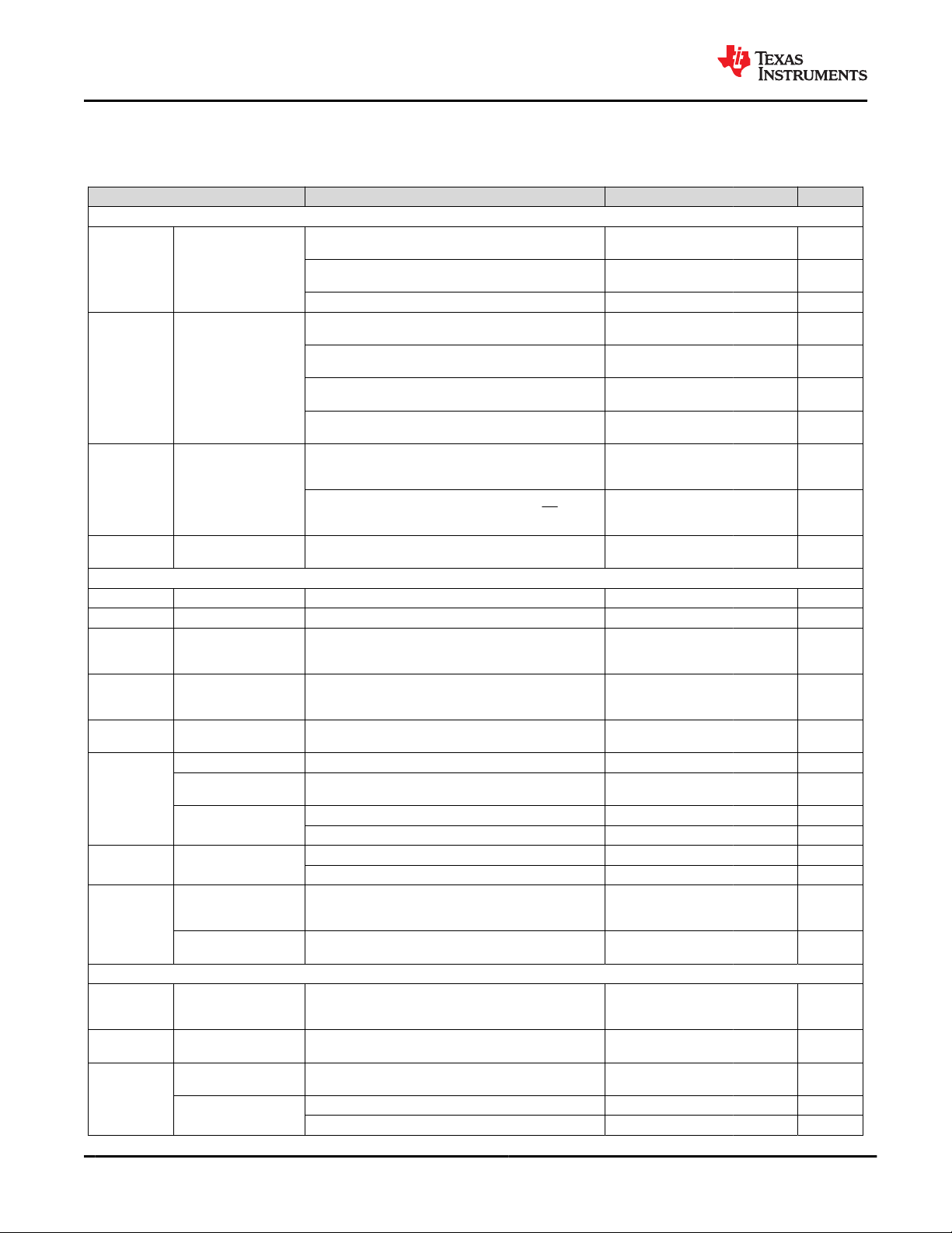
8.5 Electrical Characteristics
Circuit of Figure 8-1, V(UVLO) < VIN < V(OVP) and VIN > V(BAT) + V(SLP), TJ = –40°C to 85°C and TJ = 25°C for typical values
(unless otherwise noted)
PARAMETERS TEST CONDITIONS MIN TYP MAX UNIT
INPUT CURRENTS
IIN
Supply Current for
Control
V(UVLO) < VIN < V(OVP) and VIN > V(BAT) + V(SLP) PWM
Switching, –40°C < TJ < 85°C 1 mA
V(UVLO) < VIN < V(OVP) and VIN > V(BAT) + V(SLP) PWM NOT
Switching 3 mA
0°C < TJ < 85°C, VIN = 5 V, Charge Disabled 1.5 mA
I(BAT_HIZ)
Battery discharge current
in High Impedance Mode
0°C < TJ < 60°C, VIN = 0 V, High-Z Mode, PWM Not
Switching, V(BUVLO) < V(BAT) < 4.65 V 0.7 1.2 µA
0°C < TJ < 60°C, VIN = 0 V, High-Z Mode, PWM Not
Switching, V(BUVLO) < V(BAT) < 6.6 V 0.9 1.5 µA
0°C < TJ < 60°C, VIN = 0 V or floating, High-Z Mode, PWM
Switching, No Load 0.75 3.5 µA
0°C < TJ < 85°C, VIN = 0 V, High-Z Mode, PWM Switching,
LSLDO enabled 1.35 4.25 µA
I(BAT_ACTIVE)
Battery discharge current
in Active Battery Mode
0°C < TJ < 85°C, VIN = 0 V, Active Battery Mode, PWM
Switching, LSLDO enabled, I2C Enabled, V(BUVLO) < V(BAT) <
4.65 V
6.8 12 µA
0°C < TJ < 85°C, 0 < VIN < VIN(UVLO), Active Battery Mode,
PWM Switching, LSLDO disabled, I2C Enabled, CD = Low,
V(BUVLO) < V(BAT) < 4.65 V
6.2 11 µA
I(BAT_SHIP)
Battery discharge current
in Ship Mode 0°C < TJ < 85°C, VIN = 0 V, Ship Mode 2 150 nA
POWER-PATH MANAGEMENT and INPUT CURRENT LIMIT
VDO(IN-PMID) VIN – V(PMID) VIN = 5 V, IIN = 300 mA 125 170 mV
VDO(BAT-PMID) V(BAT) – V(PMID) VIN = 0 V, V(BAT) > 3 V, Iff = 400 mA 120 160 mV
V(BSUP1)
Enter supplement mode
threshold V(BAT) > V(BUVLO)
V(PMID) <
V(BAT) – 25
mV
V
V(BSUP2)
Exit supplement mode
threshold V(BAT) > V(BUVLO)
V(PMID) <
V(BAT) –
5mV
V
I(BAT_OCP)
Current Limit, Discharge
Mode V(BAT) > V(BUVLO) 0.85 1.15 1.35 A
I(ILIM)
Input Current Limit Programmable Range, 50-mA steps 50 400 mA
Maximum Input Current
using ILIM
K(ILIM) /
R(ILIM)
IILIM accuracy IILIM
accuracy
50 mA to 100 mA –12% 12%
100 mA to 400 mA –5% 5%
K(ILIM)
Maximum input current
factor
I(ILIM) = 50 mA to 100 mA 175 200 225 AΩ
I(ILIM) = 100 mA to 400 mA 190 200 210 AΩ
VIN(DPM)
Input voltage threshold
when input current is
reduced
Programmable Range using VIN(DPM) Registers. Can be
disabled using VIN(DPM_ON)
4.2 4.9 V
VIN_DPM threshold
accuracy –3% 3%
BATTERY CHARGER
V(DPPM)
PMID voltage threshold
when charge current is
reduced
Above V(BATREG) 0.2 V
RON(BAT-PMID)
Internal Battery Charger
MOSFET on-resistance Measured from BAT to PMID, V(BAT) = 4.35 V, High-Z mode 300 400 mΩ
V(BATREG)
Charge Voltage Operating in voltage regulation, Programmable Range, 10-
mV steps 3.6 4.65 V
Voltage Regulation
Accuracy
TJ = 25°C –0.5% 0.5%
TJ = 0°C to 85°C –0.5% 0.5%
BQ25120F3A
SLUSDI4A – OCTOBER 2018 – REVISED APRIL 2021 www.ti.com
8Submit Document Feedback Copyright © 2022 Texas Instruments Incorporated
Product Folder Links: BQ25120F3A