Texas Instruments CC1110 Programming manual
Other Texas Instruments Microcontroller manuals
Texas Instruments
Texas Instruments MSP430F6734 User manual
Texas Instruments
Texas Instruments LaunchPad MSP430FR2355 User manual
Texas Instruments
Texas Instruments CC2520 User manual
Texas Instruments
Texas Instruments Chipcon Products CC1050DK User manual
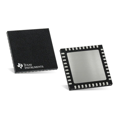
Texas Instruments
Texas Instruments CC2540 Instruction Manual
Texas Instruments
Texas Instruments MSP430F67481 User manual
Texas Instruments
Texas Instruments MSP430F6726 User manual
Texas Instruments
Texas Instruments SimpleLink CC2650 User manual
Texas Instruments
Texas Instruments MSP-EXPCC430RF Series User manual
Texas Instruments
Texas Instruments bq2415 Series User manual

Texas Instruments
Texas Instruments CC2543EM User manual
Texas Instruments
Texas Instruments LaunchPad MSP-EXP430FR5994 User manual
Texas Instruments
Texas Instruments CC3235MODSF SimpleLink User manual
Texas Instruments
Texas Instruments MSP430F67761 User manual
Texas Instruments
Texas Instruments MSP430F67771 User manual
Texas Instruments
Texas Instruments TPS65910 EVM User manual

Texas Instruments
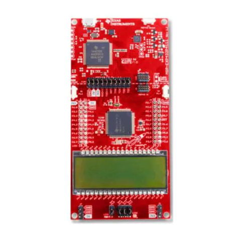
Texas Instruments MSP430F6724 User manual
Texas Instruments
Texas Instruments SimpleLink MSP432P4 Series Product manual
Texas Instruments
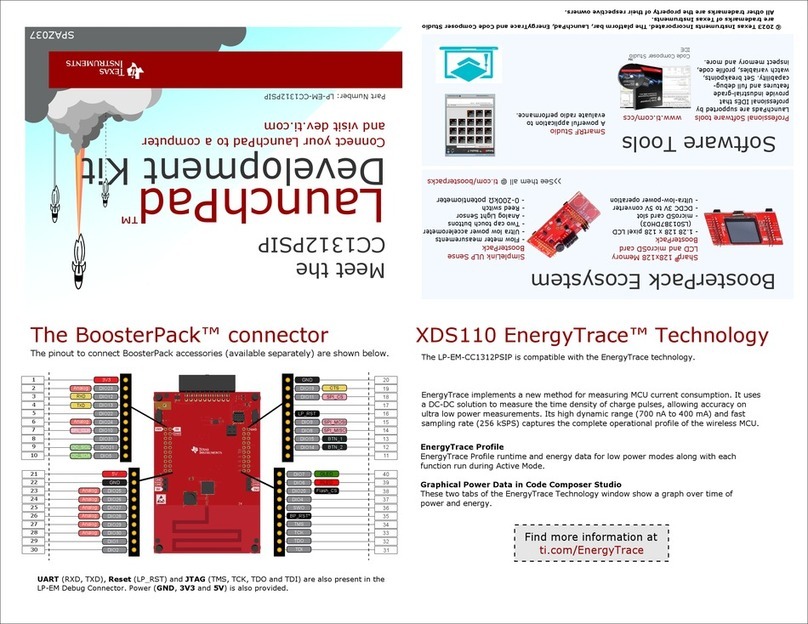
Texas Instruments LaunchPad CC1312PSIP User manual
Texas Instruments
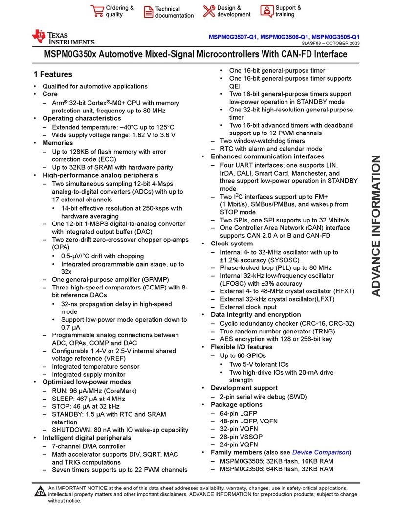
Texas Instruments MSPM0G350 Series User manual
Popular Microcontroller manuals by other brands

Novatek
Novatek NT6861 manual

Espressif Systems
Espressif Systems ESP8266 SDK AT Instruction Set

Nuvoton
Nuvoton ISD61S00 ChipCorder Design guide

STMicrolectronics
STMicrolectronics ST7 Assembler Linker user manual

Lantronix
Lantronix Intrinsyc Open-Q 865XR SOM user guide

NEC
NEC 78GK0S/K 1+ Series Application note

