User’s Guide
TMUX646EVM User's Guide
ABSTRACT
This user's guide describes the characteristics, operation, and use of the TMUX646EVM evaluation module
(EVM), which is represented by TMUX646EVM in this user's guide. A complete schematic diagram, printed-
circuit board layouts, and bill of materials are included in this document.
Table of Contents
1 Introduction.............................................................................................................................................................................2
2 Information About Cautions and Warnings..........................................................................................................................3
3 Features of this EVM.............................................................................................................................................................. 4
4 EVM Images.............................................................................................................................................................................4
5 EVM Setup............................................................................................................................................................................... 6
6 PCB Layouts..........................................................................................................................................................................12
7 Schematics............................................................................................................................................................................16
8 Bill of Materials..................................................................................................................................................................... 20
9 Related Documentation........................................................................................................................................................20
List of Figures
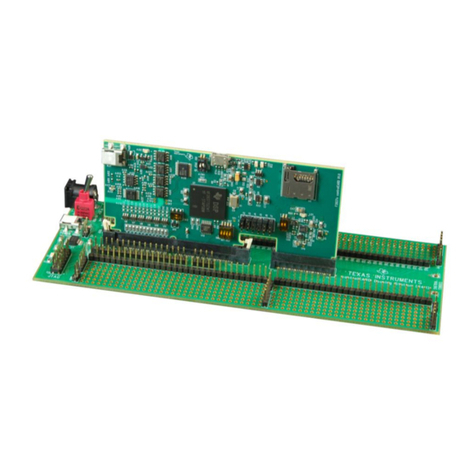
Figure 1-1. TMUX646EVM: Topside............................................................................................................................................ 2
Figure 1-2. TMUX646EVM: Backside..........................................................................................................................................3
Figure 4-1. TMUX646EVM Front and Back................................................................................................................................. 4
Figure 5-1. TMUX646EVM Power Connections for U1 and U2...................................................................................................7
Figure 6-1. Top View Illustration of the TMUX646EVM Layout..................................................................................................12
Figure 6-2. First Internal Layer Illustration of the TMUX646EVM Layout.................................................................................. 13
Figure 6-3. Second Internal Layer Illustration of the TMUX646EVM Layout............................................................................. 14
Figure 6-4. Bottom Layer Illustration of the TMUX646EVM Layout...........................................................................................15
Figure 7-1. TMUX646EVM U1 Schematic (Editor View)............................................................................................................16
Figure 7-2. TMUX646EVM U1 Schematic (DNI View)...............................................................................................................17
Figure 7-3. TMUX646EVM U2 Schematic (Editor View)............................................................................................................18
Figure 7-4. TMUX646EVM U2 Schematic (DNI View)...............................................................................................................19
List of Tables
Table 5-1. Configurable Load Matrix............................................................................................................................................6
Table 5-2. 3-Pin Header: Signal to Pin Matrix..............................................................................................................................7
Table 5-3. Jumper ID to EVM Orientation Matrix......................................................................................................................... 7
Table 5-4. TMUX646EVM: Truth Table........................................................................................................................................ 8
Table 5-5. TMUX646EVM Board Configuration – Control Signals...............................................................................................8
Table 5-6. TMUX646EVM: Logic Levels...................................................................................................................................... 8
Table 5-7. TMUX646EVM Board Configuration – I/O Signals..................................................................................................... 9
Table 8-1. TMUX646EVM Bill of Materials.................................................................................................................................20
Trademarks
All trademarks are the property of their respective owners.
www.ti.com Table of Contents
SCDU025 – MAY 2021
Submit Document Feedback
TMUX646EVM User's Guide 1
Copyright © 2021 Texas Instruments Incorporated
