manuals.online logo
Brands
  1. Home
  2. •
  3. Brands
  4. •
  5. Texas Instruments
  6. •
  7. Microcontroller
  8. •
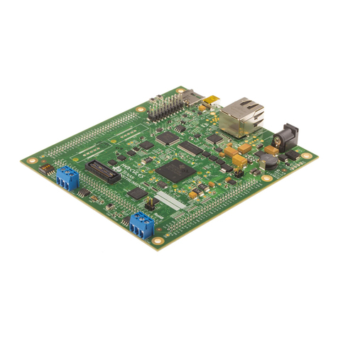
  9. Texas Instruments TIDA-00204 User manual

Texas Instruments TIDA-00204 User manual

1
JAJU324B–March 2015–Revised July 2017
TIDU832 翻訳版 —最新の英語版資料 http://www-s.ti.com/sc/techlit/TIDU832
Copyright © 2015–2017, Texas Instruments Incorporated
EMI/EMC
規格準拠、産業用温度範囲のデュアルポート・ギガビット・イーサネットの
リファレンス・デザイン
参参考考資資料料
TI Designs: TIDA-00204
EMI/EMC
規規格格準準拠拠、、産産業業用用温温度度範範囲囲ののデデュュアアルルポポーートト・・ギギガガビビッッ
トト・・イイーーササネネッットトののリリフファァレレンンスス・・デデザザイインン
概概要要
TI Designs リファレンス・デザインは、システムの迅速な評
価とカスタム化に必要な方法、試験結果、設計ファイルなど
を提供しています。開発期間の短縮に役立ちます。
リリソソーースス
TIDA-00204 デザイン・フォルダ
DP83867IR プロダクト・フォルダ
LM46002 プロダクト・フォルダ
AM3359 プロダクト・フォルダ
TPS65910A3 プロダクト・フォルダ
TPS51200 プロダクト・フォルダ
LMZ10501 プロダクト・フォルダ
TPS720 プロダクト・フォルダ
TPS737 プロダクト・フォルダ
TPD4E05U06 プロダクト・フォルダ
TPS717 プロダクト・フォルダ
TPD4S012 プロダクト・フォルダ
CDCE913 プロダクト・フォルダ
E2Eエキスパートに質問
WEBENCH®設計支援ツール
特特長長
• EMIおよびEMC規格に準拠した設計で、2つの
DP83867IRギガビット・イーサネットPHYおよび
AM3359 Sitara™プロセッサを使用して広い入力電圧
範囲(17~60V)に対応し、過酷な工業用環境で動作可
能
• CISPR 11/EN55011 Class Aの放射要件を4.3dB
超上回る
• IEC61800-3 EMCの耐性要件を上回る
– ±6kV ESD CD (IEC 61000-4-2)
– ±4kV EFT (IEC 61000-4-4)
– ±2kV サージ(IEC 61000-4-5)
• Sitara AM3359ファームウェアにUDPおよびTCP/IP
スタックと、HTTP Webサーバのサンプルが含まれてお
り、オンボードのSDカードからブートするため、スタンド
アロンで簡単に動作
• USB仮想COMポート経由でDP83867IRレジスタへアク
セスできるため、RGMII遅延モードなど、特定のカスタ
ムPHY構成が可能
•クロック・シンセサイザを使用してシステム・クロックを生
成し、ジッタと、クロックからの位相シフトを低減
アアププリリケケーーシショョンン
•産業用ドライブ
•ファクトリ・オートメーション/制御
•産業用ネットワーク
•試験および測定機器
JTAG/
UART
Micro
SD
24-V to 5-V
DC-DC
Reset
button
Magnetics
Input: 24 V
(17 V to 60 V)
Micro
USB
DDR3
Status LEDs
10/100/1000
Mb/s
Ethernet
PHY1
DP83867IR RJ45
10/100/1000
Mb/s
Ethernet
PHY2
DP83867IR
6LWDUDŒ30,&
DDR3 P/S Gigabit PHY P/S
Port 1
25-MHz clock
24-MHz
clock Host processor
SitaraŒAM3359
Magnetics
Status LEDs
RJ45 Port 2
25-MHz clock
Application firmware
- IPv4 TCP/IP
- UDP
- IP address:
192.168.1.10
- HTTP webserver
example
Clocking
Distribution
Network
CDCE913
25-MHz
clocks
24-MHz
clock
Copyright © 2017, Texas Instruments Incorporated
System Description
www.tij.co.jp
2JAJU324B–March 2015–Revised July 2017
TIDU832 翻訳版 —最新の英語版資料 http://www-s.ti.com/sc/techlit/TIDU832
Copyright © 2015–2017, Texas Instruments Incorporated
EMI/EMC
規格準拠、産業用温度範囲のデュアルポート・ギガビット・イーサネットの
リファレンス・デザイン
使用許可、知的財産、その他免責事項は、最終ページにあるIMPORTANT NOTICE(重要な注意事項)をご参照くださいますようお願いい
たします。 英語版のTI製品についての情報を翻訳したこの資料は、製品の概要を確認する目的で便宜的に提供しているものです。該当す
る正式な英語版の最新情報は、www.ti.comで閲覧でき、その内 容が常に優先されます。TIでは翻訳の正確性および妥当性につきましては
一切保証いたしません。実際の設計などの前には、必ず最新版の英語版をご参照くださいますようお願いいたします。
1 System Description
This TI design supports dual-port Gigabit Ethernet communication through twisted pair copper cable as
defined in IEEE 802.3ab. It is designed to be evaluated for harsh industrial environment with regards to
standard compliance to CISPR 11 / EN55011 Class A radiated immunity requirements and EMC immunity
requirements for ESD according to 61000-4-2, fast transient burst (EFT) according to IEC61000-4-4, and
surge according to IEC61000-4-5.
The design implements dual-port Gigabit Ethernet using two DP83867IR Gigabit Ethernet PHYs, which
are connected through the Reduced Gigabit Media Independent Interface (RGMII) to AM3359 Sitara
processor with integrated Ethernet MAC and Switch. It offers a wide input voltage range from 17 to 60 V
with nominal 24-V input voltage and meets industrial requirements for EMI and EMC.
For easy standalone operation, the host processor is configured to boot the pre-installed application
firmware from an onboard SD-Card. The application firmware implements a driver for the DP83867IR,
UDP and TCP/IP stack, and HTTP web server examples, based on TI’s SYS/BIOS Industrial SDK and TI’s
Networking Development Kit NDK. A USB virtual COM port offers optional user access to read or write to
DP83867IR registers for custom configurations like RGMII Delay Mode, if required. A JTAG interface on
the AM3359 provides the option for custom software development, test, and debug.
Therefore, this design allows for performance evaluation of two DP83867IR Gigabit Ethernet PHYs and
AM3359 Sitara processor with integrated Ethernet MAC and Switch.
1.1 Key System Specifications
This design allows for performance evaluation of two DP83867IR Gigabit Ethernet PHYs and AM3359
Sitara™ processors with an integrated Ethernet MAC and Switch. It meets industrial requirements for EMI
and EMC, supports industrial temperature grade, and offers a wide input voltage range with a default of
24 V.
www.tij.co.jp
System Description
3
JAJU324B–March 2015–Revised July 2017
TIDU832 翻訳版 —最新の英語版資料 http://www-s.ti.com/sc/techlit/TIDU832
Copyright © 2015–2017, Texas Instruments Incorporated
EMI/EMC
規格準拠、産業用温度範囲のデュアルポート・ギガビット・イーサネットのリ
ファレンス・デザイン
To allow for easy standalone operation, the AM3359 Sitara boots the application firmware from SD-Card.
The application firmware implements the driver for the DP83867IR, UDP and TCP/IP stack, and HTTP
web server examples and is based on TI’s SYS/BIOS Industrial SDK. An additional option is provided to
access the DP83867IR Gigabit Ethernet PHY registers through USB virtual COM port. A JTAG interface
option is also provided to allow for custom software development with that board.
表表 1. TIDA-00204 Hardware Specification
FUNCTION INFO SPECIFICATION COMMENT
Gigabit Ethernet IEEE 802.3ab
Number of ports 2 —
MDI 1000BASE-T (copper) —
MAC interface RGMII —
EMAC and switch Y Integrated with Sitara AM3359
Status LED Y —
IEEE 1588v2 Y Hardware enabled but not
tested
Separate transformer and
RJ45 jack YOption to place protection
diodes on either side of the
magnetics, used for test
purpose
SMI Y (2.5 MHz) —
Configurable PHY address
(SMI) Y Through strap resistors
DP83867IR
Low power 565 mW —
Integrated termination resistors Y —
RGMII Delay Mode on RX/TX Programmable —
Clock 25 MHz (< 50 ppm) —
Power
Input voltage 24 V (17 to 60 V) —
Output voltage 5 V Intermediate voltage
Output current 850 mA (nominal), 1.2 A
(maximum) —
Indicator LED Y For 5 V, 3.3 V and 2.5 V
Point of load for all ICs Y PMIC for AM3359, 3.3 V (I/O),
2.5 V and 1.1 V for PHYs
Standalone operation Boot from SD-Card interface Y —
USB virtual COM port Access to PHY registers Y Read and write operation to
both registers of PHY
supported
JTAG JTAG header Y —
Temperature range Industrial –40°C to 85°C Selected devices support
industrial temperature range
EMI CISPR 11 / EN55011 Class A radiated emissions —
EMC IEC61800-3
IEC61000-4-2 ±4-kV ESD CD,
Criterion B Shielded Ethernet cable
IEC61000-4-4 ±2-kV EFT,
Criterion B Shielded Ethernet cable
IEC61000-4-5 ±1-kV Surge,
Criterion B Shielded Ethernet cable,
min 20 m
表表 2. TIDA-00204 Firmware Specification (AM3359)
FUNCTION INFO SPECIFICATION COMMENT
Boot loader Boot application firmware from SD-Card Y —
DDR3 memory Driver for DDR3 Y —
USB virtual COM port Driver for UART Y —
System Description
www.tij.co.jp
4JAJU324B–March 2015–Revised July 2017
TIDU832 翻訳版 —最新の英語版資料 http://www-s.ti.com/sc/techlit/TIDU832
Copyright © 2015–2017, Texas Instruments Incorporated
EMI/EMC
規格準拠、産業用温度範囲のデュアルポート・ギガビット・イーサネットの
リファレンス・デザイン
表表 2. TIDA-00204 Firmware Specification (AM3359) (continued)
FUNCTION INFO SPECIFICATION COMMENT
PHY Driver for DP83867IR Y —
RTOS TI SYS/BIOS Y —
UDP and TCP/IP IPv4 protocol support Y Based on TI’s AM335x
industrial SDK and NDK
Fixed IP 192.168.1.10 —
HTTP Web server example Y Based on TI’s AM335x
industrial SDK and NDK
JTAG/
UART
Micro
SD
24-V to 5-V
DC-DC
Reset
button
Magnetics
Input: 24 V
(17 V to 60 V)
Micro
USB
DDR3
Status LEDs
10/100/1000
Mb/s
Ethernet
PHY1
DP83867IR RJ45
10/100/1000
Mb/s
Ethernet
PHY2
DP83867IR
6LWDUDŒ30,&
DDR3 P/S Gigabit PHY P/S
Port 1
25-MHz clock
24-MHz
clock Host processor
SitaraŒAM3359
Magnetics
Status LEDs
RJ45 Port 2
25-MHz clock
Application firmware
- IPv4 TCP/IP
- UDP
- IP address:
192.168.1.10
- HTTP webserver
example
Clocking
Distribution
Network
CDCE913
25-MHz
clocks
24-MHz
clock
Copyright © 2017, Texas Instruments Incorporated
Optional access
DP83867IR through
virtual COM port
Boot application
firmware from SD card
www.tij.co.jp
System Overview
5
JAJU324B–March 2015–Revised July 2017
TIDU832 翻訳版 —最新の英語版資料 http://www-s.ti.com/sc/techlit/TIDU832
Copyright © 2015–2017, Texas Instruments Incorporated
EMI/EMC
規格準拠、産業用温度範囲のデュアルポート・ギガビット・イーサネットの
リファレンス・デザイン
2 System Overview
2.1 Block Diagram
図1shows the system block diagram. The major building blocks are the DP83867IR Gigabit Ethernet
PHY, the AM3359 Sitara Host Processor, and the power supplies.
図図 1. System Block Diagram of TIDA-00204
2.2 Design Considerations
2.2.1 Gigabit Ethernet Overview
Ethernet has heavily expanded usage over the years. Ethernet became an attractive option for industrial
networking applications. The opportunity to use open protocols (such as TCP/IP over Ethernet networks)
help replace proprietary communications in industrial control and factory automation applications. When
using Ethernet, there are several speeds available today: 10 Mb/s, 100 Mb/s (Fast Ethernet), 1000 Mb/s
(Gigabit Ethernet), and 10 Gb/s (10-Gigabit Ethernet).
Gigabit Ethernet uses the extended Ethernet MAC layer interface, connected through a Gigabit Media
Independent Interface (GMII) layer to physical layer entities (PHY sublayers) such as 1000BASE-LX,
1000BASE-SX, 1000BASE-CX, and 1000BASE-T. The topology for a 1000-Mb/s full-duplex operation is
comparable to the 100BASE-T full-duplex mode, and the minimum packet transmission time has been
reduced by a factor of ten. The resulting achievable topologies for the half-duplex 1000-Mb/s CSMA/CD
MAC are similar to those found in half duplex 100BASE-T.
MDI_1+
MDI_1-
to RJ45
to PHY 1:1
System Overview
www.tij.co.jp
6JAJU324B–March 2015–Revised July 2017
TIDU832 翻訳版 —最新の英語版資料 http://www-s.ti.com/sc/techlit/TIDU832
Copyright © 2015–2017, Texas Instruments Incorporated
EMI/EMC
規格準拠、産業用温度範囲のデュアルポート・ギガビット・イーサネットの
リファレンス・デザイン
表表 3. Gigabit Ethernet Standards
IEEE STANDARD NAME MEDIUM
IEEE 802.3ab 1000BASE-T Twisted-pair copper cable
IEEE 802.3z 1000BASE-SX Fiber optic cable
1000BASE-LX Fiber optic cable
1000BASE-CX Twinax
As previously mentioned, this TI Design uses twisted-pair copper cables as defined IEEE 802.3ab.
2.2.2 Gigabit Ethernet PHY Interfaces
2.2.2.1 Medium Dependent Interface: PHY Layer 1000BASE-T
The 1000BASE-T Physical Coding Sublayer (PCS), Physical Medium Attachment (PMA), and baseband
medium specifications are intended for users who want a 1000-Mb/s performance over balanced twisted-
pair cabling systems.
The 1000BASE-T PHY supports full-duplex baseband transmission through four pairs of minimum CAT5
balanced cables. The 1000 Mb/s is achieved by transmitting through four wires pairs, each at 250 Mb/s.
Using hybrids and cancellers enable full duplex transmission by allowing symbols to be transmitted and
received on the same wire pairs at the same time. Baseband signaling with a modulation rate of 125 MBd
is used on each of the wire pairs. The transmitted symbols are selected from a four-dimensional five-level
symbol constellation (4D-PAM5). In the absence of data, idle symbols are transmitted.
The IEEE 802.3 specifies specify that a PHY with a MDI that is not a power interface (PI) should provide
electrical isolation between the port device circuits, including frame ground (if any) and all MDI leads. This
electrical isolation shall withstand at least one of the following electrical strength tests:
• 1500 VRMS at 50 to 60 Hz for 60 s
• 2250-V DC for 60 s
• A sequence of ten 2400-V impulses of alternating polarity, applied at intervals of not less than 1 s
To meet this requirement transformers are typically used for isolation. The typical transformer
configuration for 1000BASE-T can be seen in 図2for a one differential pair.
図図 2. Gigabit Ethernet Transformer (One out of Four Pairs)
Depending on the PHY device, parallel termination might be needed for each of the MDI differential signal
pair. The termination impedance is typically 100 Ωdifferentially. Newer devices like the DP83867IR
include integrated termination so no external termination resistors are required.
www.tij.co.jp
System Overview
7
JAJU324B–March 2015–Revised July 2017
TIDU832 翻訳版 —最新の英語版資料 http://www-s.ti.com/sc/techlit/TIDU832
Copyright © 2015–2017, Texas Instruments Incorporated
EMI/EMC
規格準拠、産業用温度範囲のデュアルポート・ギガビット・イーサネットの
リファレンス・デザイン
2.2.2.2 Medium Independent Interface: MAC Layer Interface
For the MAC layer interface to the Gigabit PHY, there are three different options defined in the IEEE
802.3ab standard: The standard Media Independent Interface (MII), the GMII, SGMII, or the RGMII.
2.2.2.2.1 GMII
The purpose of GMII is to make various physical media transparent to the MAC layer. The GMII accepts
either GMII or MII data, control, and status signals and routes them either to the 1000BASE-T, 100BASE-
TX, or 10BASE-T modules, respectively.
The GMII provides full-duplex operation and is an 8-bit wide transmit and receive data path interface
clocked at 125 MHz defining speeds up to 1000 Mb/s. GMII is backwards compatible with the MII
specification, thereby supporting 10 (2.5 MHz) and 100 (25 MHz) Mb/s speeds. Data and delimiters are
synchronous to clock references. It also provides a simple management interface.
The transmit signals are GTX_CLK, TX_CLK, TX_D[7:0], TX_EN, and TX_ER. The GTX_CLK signal is
supplied to the PHY when it is operating in Gigabit mode. When this is done, the TX_D, TX_EN, and
TX_ER are synchronized to the GTX_CLK signal. For a 10/100-Mb operation, the TX_CLK is supplied to
the MAC, and the TX_CLK signal is used to synchronize the signals (TX_D, TX_EN, and TX_ER). The
receiver signals are RX_CLK, RX_D[7:0], RX_DV, RX_ER, COL, and CS. The GMII uses in total a
maximum of 25 pins.
2.2.2.2.2 RGMII
The RGMII is designed to reduce the number of pins required to interconnect the MAC and PHY (12 pins
for RGMII relative to 24 pins for GMII). With this optimization, the RGMII consists of 12 signals: 6 signals
for receive, which are RX_CTL, RX_CLK, RX_D[3:0], and 6 for transmit, which are TX_CTL,
TX_CLK,TX_D[3:0]. To accomplish this, the data paths and all associated control signals are reduced and
are multiplexed. Both rising and trailing edges of the clock are used. The TX_CTL and RX_CTL signal
carries data valid (DV) on the rising edge and DV XOR ERROR on the falling edge, for CTL signals there
is no change between 10/100Mb/s or 1000Mb/s operation.
For a Gigabit operation, the GTX_CLK and RX_CLK clocks are 125 MHz, and for 10- and 100-Mb/s
operation, the clock frequencies are 2.5 MHz and 25 MHz, respectively.
2.2.2.2.3 SGMII
The SGMII differs from the GMII and RGMII by having a higher clock frequency and the 8b/10b (SerDes)
coded interface. It uses differential pairs at a 625-MHz clock frequency double data rate (DDR) for TX and
RX data and for TX and RX clock. The transmit and receive path uses one differential pair for data and in
some cases one for clock. TX and RX clocks must be generated on device output but are optional on
device input. With revision 1.8 of the SGMII standard, clock recovery can be used, removing the need for
the clock signal. This means that the SGMII can be a 4- to 8-pin solution.
System Overview
www.tij.co.jp
8JAJU324B–March 2015–Revised July 2017
TIDU832 翻訳版 —最新の英語版資料 http://www-s.ti.com/sc/techlit/TIDU832
Copyright © 2015–2017, Texas Instruments Incorporated
EMI/EMC
規格準拠、産業用温度範囲のデュアルポート・ギガビット・イーサネットの
リファレンス・デザイン
2.2.2.3 Serial Management Interface
The serial management interface (SMI) consists of a Management Data Clock (MDC) and a Management
Data Input/Output (MDIO) signal. It provides access to the PHY’s internal register space for status
information and configuration. The MDC and MDIO signals can be shared amongst several PHYs due to
the serial communication protocol, where an address is used to identify the corresponding PHY slave. The
MDIO has a standard set of registers from 0 to 31 each containing 16 bits. In IEEE 802ah clause 45, an
extended register set was defined for extra functionality of the PHYs. The SMI is initially specified at a
2.5-MHz clock.
Processor
MAC
Ethernet PHY
OS
IEEE1588 code
(Application layer) 4
3
2
1
Hardware assist
www.tij.co.jp
System Overview
9
JAJU324B–March 2015–Revised July 2017
TIDU832 翻訳版 —最新の英語版資料 http://www-s.ti.com/sc/techlit/TIDU832
Copyright © 2015–2017, Texas Instruments Incorporated
EMI/EMC
規格準拠、産業用温度範囲のデュアルポート・ギガビット・イーサネットの
リファレンス・デザイン
2.2.3 IEEE 1588v2
Precise time information is important, especially for distributed systems like in factory automation. The
IEEE 1588v2 is an IEEE standard for precision clock synchronization protocol for networked measurement
and control systems. The protocol is used to synchronize the time and clock frequency. It defines a way to
provide sub-microsecond precision synchronization.
To define this synchronization, the start of package detection is needed. Depending on which application
layer this detection happens, the timing error varies. The lower the layer, the smaller the error.
図図 3. Options 1 to 4 for Time Stamp versus Layer
The closer to the PHY the time stamp is set the better the time reference. The time stamp consists of two
signals the Ingress (RX) and Egress (TX) time stamp. Depending on when the time stamp is done, the
delay can vary from nanoseconds to microseconds.
2.3 System Design Theory
2.3.1 Circuit Design and Component Selection
2.3.1.1 DP83867IR 10/100/1000-Mb/s Gigabit Ethernet PHY
The DP83867IR was selected due to following features:
• IEEE 802.3ab 1000BASE-T compliant
• Operating temperature range –40°C to 85°C
• 8-kV IEC 61000-4-2 ESD protection (direct contact)
• RGMII with software (register) programmable and hardware configurable (strap resistors) clock skew
• Integrated termination resistors
• Low power: 565 mW
• SOF detect for IEEE 1588 time stamp
In addition to the above features, the DP83867IR also offers the following features:
• Low deterministic TX and RX latency
• Wake on LAN (WoL)
Strap (GPIO)
VDDIO
RHI
RLO
System Overview
www.tij.co.jp
10 JAJU324B–March 2015–Revised July 2017
TIDU832 翻訳版 —最新の英語版資料 http://www-s.ti.com/sc/techlit/TIDU832
Copyright © 2015–2017, Texas Instruments Incorporated
EMI/EMC
規格準拠、産業用温度範囲のデュアルポート・ギガビット・イーサネットの
リファレンス・デザイン
• Synchronized clock output to synchronize multiple PHYs using one crystal (or clock)
2.3.1.1.1 DP83867IR Gigabit Ethernet PHY Configuration
When configuring the DP83867IR, this can be done using either a SMI or a strap configuration through the
four-level strap pins. A pull-up resistor and a pull-down resistor of suggested values may be used to set
the voltage ratio of the four-level strap pin input and the supply to select one of the possible selected
modes. The device should feature four-level strap pins, each supporting at least four selectable options,
as shown in 図4and 表4. Strap resistors with 1% tolerance are recommended.
図図 4. Strap Circuit
表表 4. Four-Level Strap Resistor Ratios
MODE RESISTOR RHI (kΩ) RESISTOR RLO (kΩ)
1 OPEN OPEN
2 11 2.49
3 6.04 2.49
4 2.49 OPEN
Because this design employs two DP83867IR, the SMI will have two DP83867IR slaves addresses. This
means that the SMI address of the two DP83867IR have to differ to ensure a valid communication. To set
the DP83867IR SMI address a strap configuration option can be used on one DP83867IR to change the
default address from 0x00. In this design, it was chosen to use the pin RX_D4 to set the SMI address, as
this pin is not used for the RGMII.
A strap configuration option was chosen so the RGMII is always enabled to ensure the RGMII is enabled
when as the RX_D6 pin is used as input pin on the AM3359 Sitara processor.
As the clock out option of the device is not used by default, RX_D7 strap configuration option was done to
disable the clock out of the device. This feature is default on if this strap on is not done and if it needs to
be disabled without strap configuration. It would have to be done using the SMI.
LED_1
LED_0
VDDIO
GND
Mode 4
Mode 1
2.49 NŸ
470 Ÿ
470 Ÿ
RGMII2_RXD0
RGMII2_RXD1
RGMII2_RXD2
RGMII2_RXD3
RGMII2_RXCLK
RGMII2_RXCTRL
GND
PHY2_RX1588
PHY2_TX1588
Vddio
Vddio
Orange
1
2
D12
0
R51
0
R50
0
R47
0
R46
0
R44
0
R43
560
R60
11.0k
R49
GND
11.0k
R59
2.49k
R62
Vddio
GND
11.0k
R56
2.49k
R61
2.49k
R57
RGMII2_RXCTRL_R
RGMII2_RXCLK_R
RGMII2_RXD0_R
RGMII2_RXD1_R
RGMII2_RXD2_R
RGMII2_RXD3_R
RESERVED
1
RESERVED
7
RESERVED
9
RESERVED
16
RX_CLK
43
RX_D0
44
RX_D1
45
RX_D2
46
RX_D3
47
RX_D4/GPIO
48
RX_D5/GPIO
49
RX_D6/GPIO
50
RX_D7/GPIO
51
RX_DV/RX_CTRL
53
RX_ER/GPIO
54
COL/GPIO
55
CRS/GPIO
56
DP83867IRPAPR
www.tij.co.jp
System Overview
11
JAJU324B–March 2015–Revised July 2017
TIDU832 翻訳版 —最新の英語版資料 http://www-s.ti.com/sc/techlit/TIDU832
Copyright © 2015–2017, Texas Instruments Incorporated
EMI/EMC
規格準拠、産業用温度範囲のデュアルポート・ギガビット・イーサネットの
リファレンス・デザイン
図図 5. Schematic for DP83867IR Strap Configuration on ETH2
表表 5. DP83867IR Strap on Resistor Chosen
DP83687IR PIN NAME CONFIGURATION MODE
RX_D4 Strap resistors 2 (PHY_ADD4 = 1, only ETH2)
RX_D6 Strap resistors 2 (RGMII enable)
RX_D7 Strap resistors 2 (Clock out disable)
When using the strap configuration on a specific pin, ensure that the additional function mapped to this pin
is applicable. For example, due to this the TX_D0 to TX_D3 and RX_D0 to RX_D3 pins, which are used
by the RGMII, have not been used for strap configuration. This is because this strap resistor configuration
would have needed to be compensated with trace matching from the other RGMII pins used. Another
example is the LED indicator pins: When used with both LED functionality and strap configuration, take
caution on how to connect the LED with regards to the strap resistors. An example for strap mode 0 and
strap mode 4 with indicator LED is shown in 図6.
図図 6. Example Strap Connections With Indicator LEDs for Mode 1 and Mode 4
System Overview
www.tij.co.jp
12 JAJU324B–March 2015–Revised July 2017
TIDU832 翻訳版 —最新の英語版資料 http://www-s.ti.com/sc/techlit/TIDU832
Copyright © 2015–2017, Texas Instruments Incorporated
EMI/EMC
規格準拠、産業用温度範囲のデュアルポート・ギガビット・イーサネットの
リファレンス・デザイン
2.3.1.1.2 MAC Layer Interface
The MAC interface of this design was chosen according to minimum number of pins at lowest possible
clock frequency. See 表6of the pin definitions.
表表 6. MAC Interface Option Pinout for the Different Standards
DECISION CRITERION GMII RGMII SGMII
Number of MAC interface signals 25 12 4 or 6
Clock frequency 125 MHz 125 MHz 625 MHz
With those considerations, the choice was to use the RGMII as it is running at a lower frequency than the
SGMII. Therefore, the RGMII allows for easier PCB routing of the signals, and the number of signals is
acceptable.
The RGMII signals are not differential but single-ended, and they are referenced to a clock signal of
125 MHz. It is crucial that length matching is done properly for all signals to avoid skew due to different
propagation delay between the clock and the data signals.
For this design, the following rules were followed on the RGMII signals.
表表 7. DP83867 RGMII Design Rules on TIDA-00204 PCB
RULES DISTANCE
RGMII TX length matching 0.254 mm
RGMII RX length matching 0.254 mm
RGMII data-to-data distance separation 0.762 mm
RGMII clock-to-data distance separation 1.27 mm
RGMII clock-to-clock distance separation 1.27 mm
RGMII TX length matching 0.254 mm
RGMII RX length matching 0.254 mm
Max total trace length 63.5 mm
These rules are referenced from High-Speed Interface Layout Guidelines (SPRAAR7).
Additional considerations are to place each PHYs RGMII TX and RX on the same layer and add series
termination resistors close to the corresponding output pins. Because the DP83867IR has an integrated
50-Ωseries impedance, a 0-Ωseries termination has been placed at the DP83867 RGMII RX output pins.
This was a test and debug option and the termination resistor (array) can be removed in a production
design.
A 22-Ωseries termination resistor was placed close to the RGMII1 and RGMII2 TX pins of the AM3359
Sitara.
Green
1
2
D6
MDIO_CLK_1
MDIO_DATA_1
GND
GND
D1+
1
D1-
2
NC
6
NC
7
NC
9
NC
10
D2+ 4
D2- 5
GND 3
GND 8
U7
TPD4E05U06DQA
PHY1_TD_A_P
PHY1_TD_A_N
PHY1_TD_B_P
PHY1_TD_B_N
PHY1_TD_C_P
PHY1_TD_C_N
PHY1_TD_D_P
PHY1_TD_D_N
GND
PHY1_TD_C_P
PHY1_TD_C_N
PHY1_TD_D_P
PHY1_TD_D_N
PHY_RESETn
PHY1_INTPWDN
PHY1_CLKOUT
2
3
4
1
5
6
7
8
9
10
11
12
J4
43202-8916
Yellow
1
2
D4
Red
1
2
D5
GND
V11phy
PHY1_X_D_N
PHY1_X_D_P
PHY1_X_C_N
PHY1_X_C_P
PHY1_X_D_P
PHY1_X_D_N
PHY1_X_C_P
PHY1_X_C_N
PHY1_X_B_N
PHY1_X_B_P
PHY1_X_A_P
PHY1_X_A_N
75.0
R24
75.0
R22
75.0
R32
75.0
R37
PHY1_EARTH
1000pF
C33
PHY1_EARTH
PHY1_TD_A_P
PHY1_TD_A_N
PHY1_TD_B_P
PHY1_TD_B_N
PHY1_TD_C_P
PHY1_TD_C_N
PHY1_TD_D_P
PHY1_TD_D_N
GND
10.0k
R21
560
R25
22
R35
DNP
1.00M
R36
DNP
560
R26
560
R27
0.1µF
C27
0.1µF
C28
0.1µF
C29
0.1µF
C30
Check Vddio needed before CAP
GND
PHY1_TD_C_P
PHY1_TD_C_N
PHY1_TD_D_P
PHY1_TD_D_N
D1+
1
D1-
2
NC
6
NC
7
NC
9
NC
10
D2+ 4
D2- 5
GND 3
GND 8
U8
TPD4E05U06DQA
DNP
PHY1_X_C_P
PHY1_X_C_N
PHY1_X_D_P
PHY1_X_D_N
4.7k
R23
1000pF
C26
1000pF
C25
GNDGND
PHY1_EARTH
27pF
C31
DNP
27pF
C32
DNP
GND GND GND
4.7k
R29 Vddio
TCT1
1
TD1+
2
TD1-
3
TCT2
4
TD2+
5
TD2-
6
TCT3
7
TD3+
8
TD3-
9
TCT4
10
TD4+
11
TD4-
12 MX4- 13
MX4+ 14
MCT4 15
MX3- 16
MX3+ 17
MCT3 18
MX2- 19
MX2+ 20
MCT2 21
MX1- 22
MX1+ 23
MCT1 24
T1
HX5008FNL
1 2
25 MHz
Y1 ABM3-25.000MHZ-D2Y-T
DNP
1000pF
C34
DNP
GND PHY1_EARTH
0
R171
CDC_CLK1
0
R170
DNP
TD_P_A 2
TD_M_A 3
TD_P_B 5
TD_M_B 6
TD_P_C 10
TD_M_C 11
TD_M_D 14
TD_P_D 13
RBIAS 15
MDC 20
MDIO 21
INT/PWDN 60
RESET 59
XI 19
XO 18
CLK_OUT 22
JTAG_CLK 25
JTAG_TDO 26
JTAG_TDI 28
JTAG_TRSTN 24
LED_2 61
LED_1 62
LED_0 63
VDDA1P8 17
VDDA1P8 64
VDD1P1 8
VDD1P1 29
VDD1P1 42
VDD1P1 58
GND 65
JTAG_TMS 27
4.7pF
C261
GND 4.7pF
C262
4.7pFC263
GND 4.7pF
C264
4.7pFC265
GND 4.7pF
C266
4.7pFC267
GND 4.7pF
C268
PHY1_TD_A_P
PHY1_TD_A_N
PHY1_TD_B_P
PHY1_TD_B_N
PHY1_TD_C_P
PHY1_TD_C_N
PHY1_TD_D_P
PHY1_TD_D_N
Copyright © 2017, Texas Instruments Incorporated
www.tij.co.jp
System Overview
13
JAJU324B–March 2015–Revised July 2017
TIDU832 翻訳版 —最新の英語版資料 http://www-s.ti.com/sc/techlit/TIDU832
Copyright © 2015–2017, Texas Instruments Incorporated
EMI/EMC
規格準拠、産業用温度範囲のデュアルポート・ギガビット・イーサネットの
リファレンス・デザイン
2.3.1.1.3 Interface From PHY to RJ-45
The transformer used in the MDI connection provides DC isolation between local circuitry and the network
cable. The center tap of the isolated winding has a "Bob Smith" termination through a 75-Ωand a 1000-pF
capacitor-to-chassis ground. The termination capacitor should be voltage rated to at least 2 kV. The Bob
Smith termination reduces noise resulting from common mode current flows.
注注:A TVS diode has been placed each between the DP83867IR and the transformer and the
transformer and the RJ45 jack. This was a test and debug option only and the position
between the DP83876IR and the magnetics showed slightly better results in EMC and EMI,
as shown in 図7.
図図 7. Schematic of Media Dependent Interface of ETH1
The trace length that needs to be considered is from RJ45 to magnetic and from magnetic to DP8867IR,
for these signals they are differential pairs. This means that the signals needs to be routed differentially as
long as possible without making the traces longer than necessary. To ensure data integrity, the trace’s
difference should be below 10 mil (0.254 mm).
表表 8. Differential Signal Trace Length From PHY to Magnetic and Magnetic to RJ45 Jack
MEDIA DEPENDENT INTERFACE RJ45 TO MAGNETIC (mm) MAGNETIC TO DP8867IR (mm)
PHY1 Differential pair A (N,P) 13.0123 (N), 13.0708 (P) 10.0302 (N), 10.0302 (P)
PHY1 Differential pair B (N,P) 13.1709 (N), 13.3115 (P) 10.0223 (N), 10.0223 (P)
PHY1 Differential pair C (N,P) 13.1321 (N), 13.0146 (P) 10.0175 (N), 10.0082 (P)
PHY1 Differential pair D (N,P) 13.0804 (N), 13.0003 (P) 10.0163 (N), 10.0163 (P)
PHY2 Differential pair A (N,P) 12.9469 (N), 13.0056 (P) 13.3910 (N), 13.4938 (P)
PHY2 Differential pair B (N,P) 12.9398 (N), 13.0815 (P) 13.1988 (N), 13.1047 (P)
PHY2 Differential pair C (N,P) 13.0899 (N), 13.0409 (P) 13.0679 (N), 13.1622 (P)
PHY2 Differential pair D (N,P) 13.1864 (N), 13.1063 (P) 13.3252 (N), 13.2272 (P)
System Overview
www.tij.co.jp
14 JAJU324B–March 2015–Revised July 2017
TIDU832 翻訳版 —最新の英語版資料 http://www-s.ti.com/sc/techlit/TIDU832
Copyright © 2015–2017, Texas Instruments Incorporated
EMI/EMC
規格準拠、産業用温度範囲のデュアルポート・ギガビット・イーサネットの
リファレンス・デザイン
To ensure no unnecessary stubs, all traces are routed on the top layer. The only exception is the pins
D2_P and D2_N. Due to the RJ45 jack pin assignment without integrated transformer, this differential pair
changed the layer to minimize the overall differential trace length of the four pairs.
表表 9. RJ45 Connector Pinout
PIN SIGNAL PIN SIGNAL
1 D1_P 5 D3_N
2 D1_N 6 D2_N
3 D2_P 7 D4_P
4 D3_P 8 D4_N
2.3.1.1.4 DP83867IR Input Clock Selection
For the input clock, either a crystal or an external clock source can be used. For both cases, the clock
needs to be 25 MHz with a tolerance of less than ±50 ppm. For more details, refer to the DP83867IR data
sheet, Sections 8.2.1.2 and 8.2.1.3[1]. For this design, a 25-MHz crystal was chosen (see 2.3.1.4 for
more details).
The DP83867IR has a clock out pin CLK_OUT too. This allows to route the 25-MHz clock from one
DP83867IR PHY to the second DP83867IR PHY and eliminates the need for a crystal at the second PHY,
reducing costs. The TIDA-00204 design has been prepared for this configuration by adding series 0-Ω
resistors.
The preferred option, as realized with revision E3 of this design, is to have all system clocks in the design
synced to a single reference clock. This consolidation helps to reduce jitter between the individual clocks
on the board. This option is a key feature for system performance between the PHY and the MAC layer
communication, especially in real-time Ethernet systems. See 2.3.1.4.2 for more details.
The CDCE913 programmable 1-PLL VCXO clock synthesizer is used to generate the two 25-MHz clocks
for the DP83867IR.
2.3.1.1.5 Power and Ground Pins
For each of the three power rails on the DP83867IR, decoupling capacitors are recommended as follows.
A 1-nF capacitor is recommended be placed close to each supply pin of the DP83867IR. A 10-nF and a
10-µF capacitor are recommended per supply rail.
2.3.1.1.6 PHY RESET
The DP83867IR PHYs are automatically reset after power-up, through signal SYS_RESETn. Additionally,
the DP83867IR hardware reset signal PHY_RESETn can be issued by the Sitara AM3359 GPIO pin with
the signal GPIO_PHY_RESETn, which offers a software option to reset the PHYs if needed.
1
2
3
4
5
U11
SN74AHC1G08DCK
GND
SYS_RESETn
PHY_RESETn
GND
GPIO_PHY_RESETn
Vddio
10.0k
R38
0.01µF
C35
www.tij.co.jp
System Overview
15
JAJU324B–March 2015–Revised July 2017
TIDU832 翻訳版 —最新の英語版資料 http://www-s.ti.com/sc/techlit/TIDU832
Copyright © 2015–2017, Texas Instruments Incorporated
EMI/EMC
規格準拠、産業用温度範囲のデュアルポート・ギガビット・イーサネットの
リファレンス・デザイン
図図 8. PHY Reset Option During Power Up (SYS_RESETn) and Software Reset (GPIO_PHY_RESETn)
GND
SYS_BOOT15
SYS_BOOT14
SYS_BOOT13
SYS_BOOT12
SYS_BOOT11
SYS_BOOT10
SYS_BOOT9
SYS_BOOT8
SYS_BOOT7
SYS_BOOT6
SYS_BOOT5
SYS_BOOT4
SYS_BOOT3
SYS_BOOT2
SYS_BOOT1
SYS_BOOT0
Vaux2
10k
R83
DNP 10k
R84
10k
R85
DNP 10k
R86
DNP 10k
R87
DNP 10k
R88
DNP 10k
R89
DNP 10k
R90
DNP 10k
R91
DNP 10k
R92
DNP 10k
R93
DNP 10k
R94
10k
R95
10k
R96
10k
R97
DNP 10k
R98
DNP
100k
R101
100k
R102
DNP 100k
R103
100k
R104
100k
R105
100k
R106
100k
R107
100k
R108
100k
R109
100k
R110
100k
R111
100k
R112
DNP 100k
R113
DNP 100k
R114
DNP 100k
R115
100k
R116
System Overview
www.tij.co.jp
16 JAJU324B–March 2015–Revised July 2017
TIDU832 翻訳版 —最新の英語版資料 http://www-s.ti.com/sc/techlit/TIDU832
Copyright © 2015–2017, Texas Instruments Incorporated
EMI/EMC
規格準拠、産業用温度範囲のデュアルポート・ギガビット・イーサネットの
リファレンス・デザイン
2.3.1.1.7 Not Connected Pins on DP83867
表表 10. DP83867IR Not Connected Pins
PINS REASON
TXD4:7 Internal pull-down
TX_ER Internal pull-down
TX_CLK Output
COL Internal pull-down
CRS Internal pull-down
Reserved Reserved
JTAG (TDI, TMS, TCLK) Internal pull-up
JTAG (TDO) Output
2.3.1.2 Host Processor
The Sitara AM3359 was chosen as it has a 2-Gb Ethernet MAC with switch layer supporting RGMII to
both DP83867IRs. The MAC switch layer inside the AM3359 is supporting several features of passing
messages from one PHY to the other without the use of the core. To achieve deterministic and very low
transmit and receive latency, the ICSS/PRU subsystem can be used to capture the start of frame for IEEE
1588 time stamp. The TIDA-00204 hardware is provisioned for this feature but not tested.
2.3.1.2.1 AM3359 Boot Mode Configuration
The AM3359 internal ROM code selects the corresponding peripheral based on the level of the SYSBOOT
configuration at power on reset of the device. For the full details of this boot procedure, read Sections
26.1.5 to 26.1.8 of the Technical Reference Manual of the AM335x Sitara processors.
For easy standalone operation, the AM3359 has been configured to boot from MMC1/SD-Card. This
configuration requires the SYSBOOT[15:0] pins to be "0100 0000 0001 1100". This is achieved by setting
the corresponding pull-up and pull-down resistors as per the schematics in 図9.
図図 9. AM3359 SYSBOOT Pin Configuration for MMC1/SD-Card Boot Mode
www.tij.co.jp
System Overview
17
JAJU324B–March 2015–Revised July 2017
TIDU832 翻訳版 —最新の英語版資料 http://www-s.ti.com/sc/techlit/TIDU832
Copyright © 2015–2017, Texas Instruments Incorporated
EMI/EMC
規格準拠、産業用温度範囲のデュアルポート・ギガビット・イーサネットの
リファレンス・デザイン
2.3.1.2.2 AM3359 GPIO Pin Assignment
When using the Sitara before starting the design, ensure that the peripherals functions required for the
design can be assigned to the specific GPIO pins without a mux conflict. For this purpose, there is a pin
mux tool utility for TI processors called PINMUXTOOL-V3. The tool can be downloaded from the TI
website (www.ti.com). There are specific versions pending the device, part, and package. This tool is a
huge help for AM3359 pin assignment.
This design uses the following peripherals: EMAC with RGMII1 and RGMII2, UART, MMC0 and MMC1,
MDIO, SDRAM/DDR3, I2C, and ECAP.
The pin mux tool was used to find the optimum pin assignment for the different peripherals used in the
TIDA-00204 reference design.
表表 11. AM3359 Pin Assignment
SIGNAL PINS (GPIO MODE) AMOUNT OF PINS
RGMII1 J16-J18, K15-K18, L15-L18, M16 (Mode 2) 12
RGMII2 R13-14, V14-V17, U14-U16, T14-T16 (Mode 2) 12
UART G15-G16(Mode 3) 2
MMC U9, V9 (Mode 2), U7, V7, R8, T8 (Mode 1) 6
MDIO M17-M18 (Mode 0) 2
JTAG Fixed pins not available with mux 8 to 11
SDRAM (DDR3) Fixed pins not available with mux 52
I2C C16-C17 (Mode 0) 2
ECAP U13 (Mode 5), C15 (Mode 2), C18 (Mode 0), E15 (Mode 4) 4
The remaining pins could be used in GPIO mode or assigned to unused peripherals on the AM3359
device.
IO1
1
IO2
2
IO3
3
NC
4
GND 5
IO4 6
IO5 7
IO6 8
NC 9
VCC
10
U18
TPD6E001RSER
MMC1_CLK
MMC1_CMD
MMC1_DAT0
MMC1_DAT1
MMC1_DAT2
MMC1_DAT3
GND
Vmmc
Vmmc
GND DAT2
1
CD/DAT3
2
CMD
3
VDD
4
CLK
5
VSS
6
DAT0
7
DAT1
8
S3 13
S4 14
S1 9
SW
11 CD
10 S2 12
J6
502774-0891
MicroSD_case
GND
10k
R120
10k
R121
10k
R122
10k
R123
10k
R124
10k
R125
0.1µF
C203
10µF
C202
0.01µF
C205
0.1µF
C206
MicroSD_caseGND
System Overview
www.tij.co.jp
18 JAJU324B–March 2015–Revised July 2017
TIDU832 翻訳版 —最新の英語版資料 http://www-s.ti.com/sc/techlit/TIDU832
Copyright © 2015–2017, Texas Instruments Incorporated
EMI/EMC
規格準拠、産業用温度範囲のデュアルポート・ギガビット・イーサネットの
リファレンス・デザイン
2.3.1.2.3 MMC1 Micro SD-Card
図10 shows the micro SD-Card interface including ESD protection device on the TIDA-00204. The
TPD6E001 is a low-capacitance ±15-kV ESD-protection diode array designed to protect sensitive
electronics attached to communication lines. Each channel consists of a pair of diodes that steer ESD
current pulses to VCC or GND. The TPD6E001 protects against ESD pulses up to ±15-kV human-body
model (HBM), ±8-kV contact discharge (CD), and ±15-kV air-gap discharge, as specified in
IEC 61000-4-2.
図図 10. MMC1 Micro SD-Card Interface With ESD Protection
2.3.1.2.4 I2C Communication to PMIC and EEPROM
The I2C module 0 is used for communicating with both, the EEPROM, and the Power Management IC
(PMIC). The PMIC I2C is hardcoded to the I2C address equal to 0101101 binary or 0x2D in hex.
The EEPROM was given the binary address 1010000 equal to 0x50 in hex. This is done by setting the A2,
A1, and A0pin. This then forms the 7-bit address as "1010A2A1A0".
www.tij.co.jp
System Overview
19
JAJU324B–March 2015–Revised July 2017
TIDU832 翻訳版 —最新の英語版資料 http://www-s.ti.com/sc/techlit/TIDU832
Copyright © 2015–2017, Texas Instruments Incorporated
EMI/EMC
規格準拠、産業用温度範囲のデュアルポート・ギガビット・イーサネットの
リファレンス・デザイン
2.3.1.2.5 DDR3 RAM
For this design, the MT41J128M16JT-125K TR DDR3 RAM was chosen to leverage experience from the
TI AM3359 Industrial Communications Engine development platform with part number TMDSICE3359.
This memory requires a 1.5-V supply with a rise time better than 200 ms. During this time a VTT supply
needs to be provided as this rail is a system supply for signal termination resistors. Once powered, the
device needs to be reset before going into the initialization state. Then the memory is ready for operation.
Due to the speed of the signals to the DDR3 RAM, length matching and termination are important to
ensure performance. For the data lines, length matching was done by defining different net classes with
specific considerations. The concept of defining different net classes is important when routing high speed
signals, as they can insure timing constraints or timing relationships. When defining these groups, it is
important to understand the basics of the DDR3 memory signals. For DDR3, the signals can be divided
into four different groups that have similar requirements.
表表 12. DDR3 Net Class Definitions
NET CLASS SIGNALS
Data DDR_D[15:0],DDR_DQM[1:0], DDR_DQS0[_P and _N], DDR_DQS1[_P and _N]
Address/Command DDR_A[13:0],DDR_BA[2:0], DDR_CASN, DDR_RASN, DDR_WEN
Control DDR_CKE, DDR_CSN, DDR_ODT, DDR_RESETN
Clock DDR_CLK_N,DDR_CLK_P
For the different groups, it is possible with either software or hardware to shift the sampling point. Even
with this feature of DDR3 RAM, it is still needed to do a timing budget calculation. With this calculation, it
is possible to have an estimation of how the length matching needs to be. Length matching is needed due
to the fact that the typical propagation delay for the FR4 PCB is approximately 6.5 ps/mm and so a length
mismatch would lead to a delay of the signal compared to the other signal lines. As an example the net
class data has been matched as seen in 表13.
表表 13. DDR3 Trace Length on PCB for Net Class Data
SIGNAL TRACE LENGTH (mm) SIGNAL TRACE LENGTH (mm)
DDR_D0 27.4776 DDR_D8 25.3669
DDR_D1 27.6777 DDR_D9 25.2680
DDR_D2 27.4567 DDR_D10 25.4147
DDR_D3 27.2947 DDR_D11 25.6113
DDR_D4 27.4070 DDR_D12 25.6584
DDR_D5 27.5413 DDR_D13 25.3574
DDR_D6 27.4398 DDR_D14 25.5648
DDR_D7 27.3044 DDR_D15 25.4486
DDR_DQM0 27.3479 DDR_DQM1 25.4907
DDR_DQS0_N 27.4755 DDR_DQS1_N 25.4209
DDR_DQS0_P 27.4726 DDR_DQS1_P 25.4285
System Overview
www.tij.co.jp
20 JAJU324B–March 2015–Revised July 2017
TIDU832 翻訳版 —最新の英語版資料 http://www-s.ti.com/sc/techlit/TIDU832
Copyright © 2015–2017, Texas Instruments Incorporated
EMI/EMC
規格準拠、産業用温度範囲のデュアルポート・ギガビット・イーサネットの
リファレンス・デザイン
Termination was done with parallel termination of 47 Ωto improve performance. Arrays were chosen here
to minimize size.
Further general considerations are:
• All nets in the address and command fly-by groups shall have the same number of vias in each length-
matched segment. Ground vias are placed to ensure a proper current return path. Minimize use of vias
on signal traces as they negatively impact signal integrity.
• The single-ended Address/Command net class and the control net class needs external termination to
VTT.
• For the data net class within a byte lane, the data bits can be swapped to simplify routing.
• Organize the power, ground, and signal planes to eliminate or significantly reduce the number of split
or cut planes present in the design (no splits are allowed under any DDR3 routes).
• Maintain an acceptable level of skew across the entire DDR3 interface (by net class).
• It is strongly recommended that all nets be simulated to assure proper design, performance, and signal
integrity.
• Take into account the differences in propagation delays between microstrip and stripline nets when
evaluating timing constraints. All long routes should be stripline to reduce EMI and timing skew, and
any microstrip routed for BGA breakouts should be as short as possible.
• Routes along the same path and routing segment must have the same number of vias. Vias can be
blind, buried, or HDI microvia for improved signal integrity, but are not required for standard data rates.
Similarly, back drilling vias is not required for standard data rates but can be used to eliminate via
stubs.
• For this design, the DDR3 layout was copied from the TI AM3359 Industrial Communications Engine
development platform with part number TMDSICE3359 to leverage a working and fully tested design
with the peripheral settings for the DDR3 interface.
2.3.1.2.6 AM3359 Clocking Options
For the clock, either a crystal or a digital clock source can be used. For both cases, the clock needs to be
19.2, 24, 25, or 26 MHz with a tolerance of ±50 ppm. For more details, see Section 6.2.2 of the AM3359
data sheet[5]. For this design, a 24-MHz crystal was chosen as used with the TMDSICE3359 AM3359
Industrial Communications Engine development platform.
The preferred option, as realized with revision E3 of this design, is to have all system clocks in the design
synced to a single reference clock. This consolidation helps to reduce jitter between the individual clocks
on the board. This option is a key feature for system performance between the PHY and the MAC layer
communication, especially in real-time Ethernet systems. See 2.3.1.4.2 for more details.
The CDCE913 programmable 1-PLL VCXO clock synthesizer is used to generate the 24-MHz clock for
the AM3359.
2.3.1.2.7 Power Supply Pins
For the decoupling capacitors on the different power rails of the AM3359, see Section 5.9 of the AM3359
data sheet[5].

Other Texas Instruments Microcontroller manuals
Texas Instruments TPS2379 EVM User manual

Texas Instruments

Texas Instruments TPS2379 EVM User manual

Texas Instruments AFE722 Series User manual

Texas Instruments

Texas Instruments AFE722 Series User manual

Texas Instruments TMS320F28376D User manual

Texas Instruments

Texas Instruments TMS320F28376D User manual

Texas Instruments LAUNCHXL-CC1310 Manual

Texas Instruments

Texas Instruments LAUNCHXL-CC1310 Manual

Texas Instruments AFE4403 User manual

Texas Instruments

Texas Instruments AFE4403 User manual

Texas Instruments MSPM0G310 Series User manual

Texas Instruments

Texas Instruments MSPM0G310 Series User manual

Texas Instruments CC-Antenna-DK2 User manual

Texas Instruments

Texas Instruments CC-Antenna-DK2 User manual

Texas Instruments BQ769142 User manual

Texas Instruments

Texas Instruments BQ769142 User manual

Texas Instruments CC1110 User manual

Texas Instruments

Texas Instruments CC1110 User manual

Texas Instruments DV2031S2 User manual

Texas Instruments

Texas Instruments DV2031S2 User manual

Texas Instruments Vision SDK Linux User manual

Texas Instruments

Texas Instruments Vision SDK Linux User manual

Texas Instruments Serial Programming Adapter MSP430 User manual
Texas Instruments

Texas Instruments Serial Programming Adapter MSP430 User manual

Texas Instruments Stellaris LM3S9B96 User manual

Texas Instruments

Texas Instruments Stellaris LM3S9B96 User manual

Texas Instruments Chipcon Products CC1050DK User manual

Texas Instruments

Texas Instruments Chipcon Products CC1050DK User manual

Texas Instruments CDT370 User manual

Texas Instruments

Texas Instruments CDT370 User manual

Texas Instruments SWRU351 User manual

Texas Instruments

Texas Instruments SWRU351 User manual

Texas Instruments MSP430F67771 User manual

Texas Instruments

Texas Instruments MSP430F67771 User manual

Texas Instruments TPS3703 User manual

Texas Instruments

Texas Instruments TPS3703 User manual

Texas Instruments CC3100 SimpleLink User manual

Texas Instruments

Texas Instruments CC3100 SimpleLink User manual

Texas Instruments MSP430F533x User manual

Texas Instruments

Texas Instruments MSP430F533x User manual

Texas Instruments OMAP35 Series User manual

Texas Instruments

Texas Instruments OMAP35 Series User manual

Texas Instruments SimpleLink CC3200 Wi-Fi User manual

Texas Instruments

Texas Instruments SimpleLink CC3200 Wi-Fi User manual

Texas Instruments TLC2543 User manual

Texas Instruments

Texas Instruments TLC2543 User manual

Texas Instruments TMS570LC43x User manual

Texas Instruments

Texas Instruments TMS570LC43x User manual

Popular Microcontroller manuals by other brands

Cypress CY8CKIT-001 Guide

Cypress

Cypress CY8CKIT-001 Guide

Cypress PSoC 3 quick start guide

Cypress

Cypress PSoC 3 quick start guide

sparkfun Roshamglo Badge Kit HOOK-UP GUIDE

sparkfun

sparkfun Roshamglo Badge Kit HOOK-UP GUIDE

Phytec phyCORE-167CS Hardware manual

Phytec

Phytec phyCORE-167CS Hardware manual

Intrinsyc Open-Q 212A quick start guide

Intrinsyc

Intrinsyc Open-Q 212A quick start guide

Intel Agilex user guide

Intel

Intel Agilex user guide

TECSYSTEM NT538 WS instruction manual

TECSYSTEM

TECSYSTEM NT538 WS instruction manual

Silicon Laboratories C8051F32 Series user guide

Silicon Laboratories

Silicon Laboratories C8051F32 Series user guide

Abov MC96F6432A user manual

Abov

Abov MC96F6432A user manual

National Instruments sbRIO-9651 quick start guide

National Instruments

National Instruments sbRIO-9651 quick start guide

Silicon Laboratories C8051F340 user guide

Silicon Laboratories

Silicon Laboratories C8051F340 user guide

Xilinx MIcroBlaze Development Spartan-3E 1600E Kit user guide

Xilinx

Xilinx MIcroBlaze Development Spartan-3E 1600E Kit user guide

Maxim MAX739 manual

Maxim

Maxim MAX739 manual

Cypress PSoC CY8CTMG20 Series Technical reference manual

Cypress

Cypress PSoC CY8CTMG20 Series Technical reference manual

Renesas RL78/I1A user manual

Renesas

Renesas RL78/I1A user manual

Microchip Technology SAMR34 Xplained PRO quick start guide

Microchip Technology

Microchip Technology SAMR34 Xplained PRO quick start guide

Matrix eBLOCKS EB061 manual

Matrix

Matrix eBLOCKS EB061 manual

Infineon Technologies XC800 user manual

Infineon Technologies

Infineon Technologies XC800 user manual

manuals.online logo
manuals.online logoBrands
  • About & Mission
  • Contact us
  • Privacy Policy
  • Terms and Conditions

Copyright 2025 Manuals.Online. All Rights Reserved.