User’s Guide
TPA6304-Q1 Evaluation Module
Robert Clifton
ABSTRACT
This manual describes the operations of the TPA6304Q1EVM. The TPA6304Q1EVM is a stand-alone Evaluation
Module (EVM). The PurePath™ Control Console 3 GUI (PPC3) is used to initialize and operate the EVM.
Table of Contents
1 Required Equipment and Accessories:................................................................................................................................3
2 Hardware Overview................................................................................................................................................................ 4
2.1 TPA6304Q1 Evaluation Module Description...................................................................................................................... 4
2.2 TPA6304-Q1 Evaluation Module Functions....................................................................................................................... 5
3 Software Overview..................................................................................................................................................................6
3.1 PurePath™ Console 3 (PPC3) Access and Description.................................................................................................... 6
3.2 PurePath™ Console 3 – TPA6304Q1EVM Home Window................................................................................................8
3.3 PurePath™ Console 3 – TPA6304Q1EVM Register Map Window.................................................................................... 9
3.4 PurePath™ Console 3 – TPA6304Q1EVM Monitor & Control Window........................................................................... 10
4 TPA6304-Q1 Start Up............................................................................................................................................................ 11
4.1 TPA6304Q1EVM Setup....................................................................................................................................................11
4.2 TPA6304-Q1 Settings on Device Monitor & Control Window...........................................................................................12
4.3 TPA6304-Q1 Settings on Register Map Window............................................................................................................. 17
4.4 I2C Monitor Window.........................................................................................................................................................17
5 Board Layout, Schematic and Bill of Materials..................................................................................................................19
5.1 Board Layout....................................................................................................................................................................19
5.2 Schematic........................................................................................................................................................................ 21
5.3 Bill of Materials.................................................................................................................................................................24
Revision History.......................................................................................................................................................................28
List of Figures
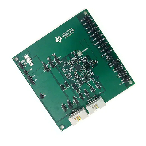
Figure 2-1. TPA6304Q1EVM....................................................................................................................................................... 4
Figure 2-2. EVM Block Diagram.................................................................................................................................................. 5
Figure 3-1. PPC3 Download Window.......................................................................................................................................... 6
Figure 3-2. PPC3 Window........................................................................................................................................................... 6
Figure 3-3. Available Apps Window.............................................................................................................................................7
Figure 3-4. PPC3 Downloading App............................................................................................................................................7
Figure 3-5. PPC3 Installed Apps................................................................................................................................................. 8
Figure 3-6. TPA6304Q1EVM Home Window...............................................................................................................................8
Figure 3-7. TPA6304Q1EVM Register Map Window...................................................................................................................9
Figure 3-8. TPA6304Q1EVM Device Monitor & Control Window.............................................................................................. 10
Figure 4-1. TPA6304Q1EVM Connections................................................................................................................................ 11
Figure 4-2. Device Monitor & Control Window...........................................................................................................................12
Figure 4-3. Device State Control Section.................................................................................................................................. 12
Figure 4-4. Master Mode/Slave Mode Section.......................................................................................................................... 13
Figure 4-5. Channel Control Section......................................................................................................................................... 13
Figure 4-6. Miscellaneous Control Section................................................................................................................................ 13
Figure 4-7. Fault / Warning Signal Configuration Section..........................................................................................................14
Figure 4-8. Faults / Warnings Section........................................................................................................................................14
Figure 4-9. AC Load Diagnostics Section..................................................................................................................................15
Figure 4-10. DC Load Diagnostics Section................................................................................................................................15
www.ti.com Table of Contents
SLAU813A – SEPTEMBER 2019 – REVISED OCTOBER 2020
Submit Document Feedback
TPA6304-Q1 Evaluation Module 1
Copyright © 2020 Texas Instruments Incorporated
