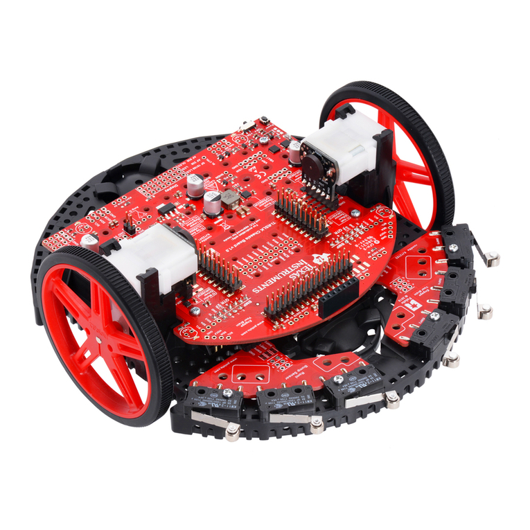
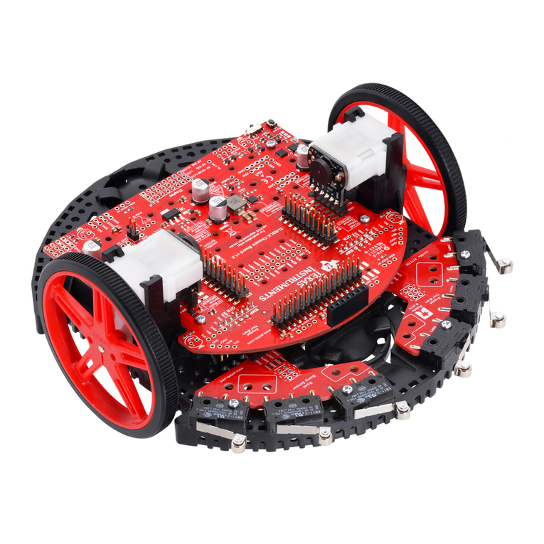
- Test Programs: try one component at a me. Make sure they work.
I/O Module Troubleshoong
My White LED I/O Module is not working what should I do?
The following troubleshoong steps will help determine if there is something wrong with the white LED I/O module.
- Ensure that the LED is properly inserted in the socket.
- Insert LED into socket - longer leg (lead) is posive (anode). If both leads are of equal length, the lead adjacent to the flat edge on LED
casing is the negave (cathode) lead.
- Download the test program and run this to test your white LED module component.
- Ensure that you have connected the I/O module into correct port required by the program
My Analog Light Sensor I/O Module is not working what should I do?
The following troubleshoong steps will help determine if there is something wrong with the analog light sensor I/O module.
- Download the test program and run this to test your analog light sensor I/O module component.
- Ensure that you have connected the I/O module into correct port required by the program
My Vibraon Motor I/O Module is not working what should I do?
The following troubleshoong steps will help determine if there is something wrong with the vibraon motor I/O module.
- Download the test program and run this to test your vibraon motor I/O module component.
- Ensure that you have connected the I/O module into correct port required by the program.
My Servo Motor I/O Module is not working what should I do?
The following troubleshoong steps will help determine if there is something wrong with the servo motor I/O module.
- Download the test program and run this to test your servo motor I/O module component.
- Ensure that you have connected the I/O module into OUT3 and that the program you are using is calling OUT3.
- The servo motor requires the TI-Innovator™ Hub to have external power. The PWR connector on the Hub lets you connect an auxiliary power
source. You can use the TI Wall Charger or the External Baery. External power is required if the TI-Innovator™ Hub is being used with a
graphing calculator or being used with the TI-Nspire™ CX computer soware.
- Overme the servo motor may need to be recalibrated. Steps to recalibrate:
- Connect External Power to TI- Innovator HUB
- Connect Servo Motor to OUT3
- Send the Command "CONNECT SERVO 1 TO OUT3"
- Send the Command "SET SERVO 1 CW 0 TIME 100" (Sets speed to zero, me value can be increased if needed)
- If the Servo does not move, then it’s already calibrated, If the servo is moving, use a screwdriver to move the potenometer in the back
of the motor unl it stops.
My Ultrasonic Ranger I/O Module is not working what should I do?
The following troubleshoong steps will help determine if there is something wrong with the ultrasonic ranger I/O module.
- Download the test program and run this to test your ultrasonic ranger I/O module component.
- Ensure that you have connected the I/O module into correct port required by the program.
The on-board light brightness sensor and the analog light sensor I/O module give slightly different readings why?
The posion of the sensor built-in to the TI-Innovator™ Hub can cause slightly different reading that those of the Analog Light Sensor.
TI-SensorLink Troubleshoong
• TI-SensorLink is not a data collecon soluon. USB connected probes or Lab Cradle remains a superior soluon for pure data collecon and analysis.
• The Hub commands for the TI-SensorLink with the Vernier analog sensors are currently not part of the Hub App (CE family) or the Hub menu (TI-
