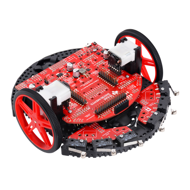
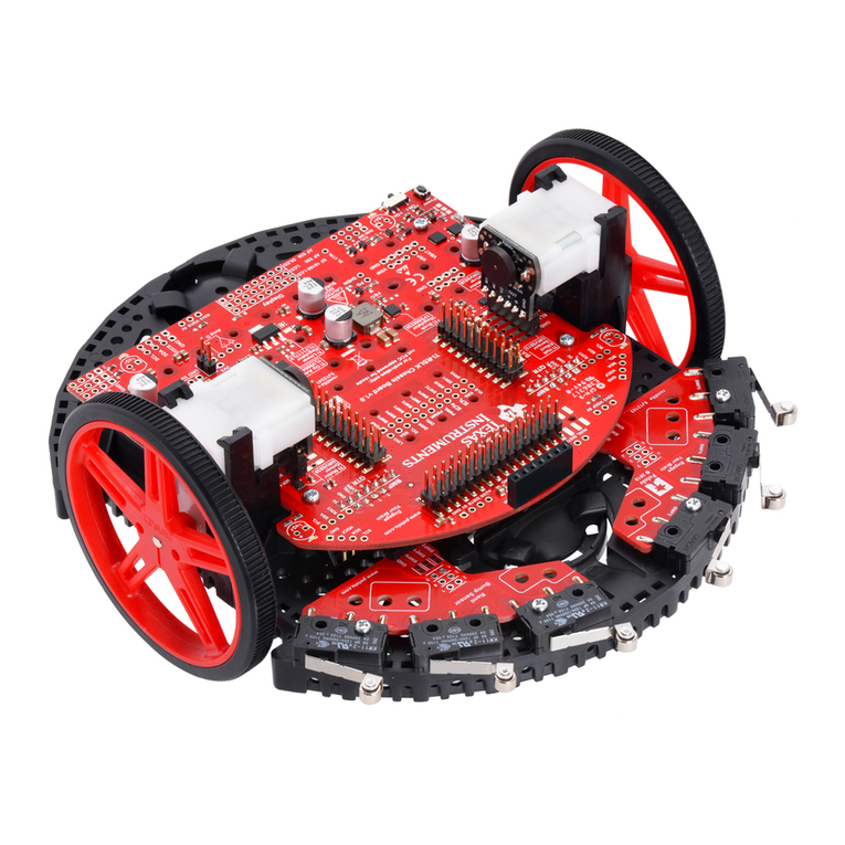
Texas Instruments TI-RSLK Instructions for use

Texas Instruments Robotics System
Construction guide

Construction guide
2
Texas Instruments Robotics System Learning Kit: The Solderless Maze Edition
SEKP164
Table of Contents
Section I Assembly guide....................................................................................... 4
1.0 Needed Items...................................................................................................... 4
1.2 Installing the motor clips............................................................................... 7
1.3 Motor installment................................................................................................ 8
1.4 Tire and wheel installment........................................................................... 9
1.5 Ball caster installment ..................................................................................10
1.6 The 8 channel QTRX line following sensor installment .................12
1.7 MSP432P401R LaunchPad installment .................................................14
1.8 Install six AA-sized batteries into the battery compartment........16
Section II LaunchPad preparation...................................................................18
2.0 Needed Items....................................................................................................18
2.1 Install 2x19 header onto the LaunchPad ..............................................18
2.2 Install 2x1 Header onto LaunchPad ........................................................19
2.3 Remove the 5V jumper .................................................................................20
Section III: Disassembly guide ..........................................................................22
3.0 Needed Items....................................................................................................22
3.1 Remove batteries and QTRX line following sensor...........................22
3.3 Remove MSP432P401R LaunchPad........................................................23
3.4 Remove the Motors ........................................................................................24
3.5 Remove the two bumper switch boards................................................25
3.6 Remove the chassis board ...........................................................................25
Section IV: Attaching the display .....................................................................28
4.0 Needed Items ....................................................................................................28
4.1 Install 1x9 header onto the TI-RSLK Max chassis board ................29
4.2 Attach the display to the header...............................................................30
Construction guide
3
Texas Instruments Robotics System Learning Kit: The Solderless Maze Edition
SEKP164
Assembly guide

Construction guide
4
Texas Instruments Robotics System Learning Kit: The Solderless Maze Edition
SEKP164
Section I Assembly guide
This section will cover the basic assembly of the parts associated with
the TI-RSLK MAX Robot. You will also learn how to install the TI
MSP432 LaunchPad on the robot.
1.0 Needed Items
The following items included in your kit (Figure 1) will be needed to
construct the TI-RSLK Max:
•One Romi chassis plastic base plate (black) with the TI-RSLK
chassis board and battery installed
•One right and one left bumper assembly, along with four nuts
and four 7/16th inch long bolts
•One 8-channel QTR reflectance sensor array
•Two Romi chassis motor clips
•Two Romi gear motors with encoders
•Two Romi wheels with tires
•One Romi ball caster kit
•One TI MSP432P401R LaunchPad development with the
required headers (2x19 and 2x1) attached
You will also need a Phillips head screwdriver, which is not included in
the kit.
Figure 1. Needed items shown above

Construction guide
5
Texas Instruments Robotics System Learning Kit: The Solderless Maze Edition
SEKP164
1.1 Installment of the two bumper switch boards
The following steps will be used to show how to install the two bumper
switch boards at the front (curved) end of the TI-RSLK Max. For this
step, you’ll need the left and right bumper switch boards and a set of
two 7/16” bolts and two nuts for each board as shown in Figure 2.
Figure 2. Required parts to install the left and right bumper
switch boards
Each bumper switch board has a 4-pin male header that needs to be
inserted horizontally into a corresponding 4-pin female header on the
front, curved end of the TI-RSLK. These female headers can be found
on the underside of the chassis board at the edge of the curved end see
(Figure 3).
Figure 3. Location of the female headers for the bumper switch boards
Figure 4. Insertion of bumper switch board into female header as shown
in Figure 3

Construction guide
6
Texas Instruments Robotics System Learning Kit: The Solderless Maze Edition
SEKP164
Next secure the bumper switch boards to the plastic chassis using the
four 7/16” bolts and nuts. The required holes for these bolts are shown in
Figure 5. Please note that we recommend inserting the bolts from the
underside of the chassis rather than the top, unlike what is shown in
Figure 5.
Figure 5. Location of holes to secure the bumper switch boards.
We recommend inserting the bolts for easier tightening of the screw due
to the front lip of the chassis side.

Construction guide
7
Texas Instruments Robotics System Learning Kit: The Solderless Maze Edition
SEKP164
1.2 Installing the motor clips
The following steps will show you how to install the motor clips to the
plastic chassis. This step should be done before inserting motors
otherwise it will not fit. The motor clips are identical, so they can be
installed on either side of the board.
The motor clips must be installed from underneath the chassis with the
motor retaining barbs facing upwards. You’ll notice that there are
grooves in the plastic chassis and guide rails on the motor clips that will
only allow you to orient and install the clips in one direction (Figure 6).
With the motor clip aligned with the grooves as just instructed, push the
motor clip all the way up into the plastic base plate. You may hear clicks
along the way, but it is not fully secured and correctly installed until the
bottom of the motor clip is flush with the bottom of the plastic chassis
plate (Figure 7). Please double check this. If the motor clip is not fully
secured with the inner barb over the top of the plastic chassis plate, then
you risk breaking this barb when you insert the motor.
Figure 6. View showing both sides of the motor clips and the 3 barbs
and guide rails.
Figure 7. Motor clip is fully installed when the bottom is flush with the
plastic chassis

Construction guide
8
Texas Instruments Robotics System Learning Kit: The Solderless Maze Edition
SEKP164
1.3 Motor installment
The following steps will be used to show how to properly insert both
motors into the motor clips. The motors are identical so either motor can
be placed on either side of the board.
Align the motor assembly such that the motor’s circuit board and pins
point towards the chassis board and the metal motor shaft points
outwards and away from the robot (Figure 8).
Figure 8. Picture showing properly motor alignment and black plastic
barbs holding the motors in place.
Once aligned, begin to insert the motor into the motor clips by gently
spreading apart the black plastic retaining barbs. Before pressing the
motor down, ensure that the motor is aligned evenly within the motor clip
and ensure that the pins of the header are properly aligned with the
connector on the chassis board (Figure 9).
Figure 9. Ensure the motor is straight and pins are aligned before
pressing down firmly.

Construction guide
9
Texas Instruments Robotics System Learning Kit: The Solderless Maze Edition
SEKP164
1.4 Tire and wheel installment
The following steps will be used to show how to assemble the tires onto
the wheels and insert the wheel assembly onto the motors.
The rubber tires first need to be installed onto the wheels as shown in
Figure 10. This can be a challenging exercise since the tires must be
stretched greatly to fit onto the wheels.
Figure 10. Tires properly installed onto the wheels. Notice the “D”
shaped hole in the center of the wheel.
Before installing the wheels, please notice the “D” shaped hole in the
center of the wheel. This shape aligns with the “D” shaped metal motor
shaft on the motor assembly. Also notice that the plastic immediately
surrounding the “D” shape on the wheel protrudes out on one side, while
the other side is flat. The protruding side of the wheel should face the
robot to create space away from the robot chassis and reduce any
possible friction.
With the protruding end of the wheel pointing towards the robot, align the
“D” shapes on the wheel and motor shaft, and then begin pressing the
wheel onto the motor. It may require significant force to press the wheel
fully onto the motor shaft while ensuring proper alignment. One
technique to apply the required force is to put the chassis on its side and
press the chassis down against the table to insert the wheel fully onto the
motor shaft (Figure 11).
Figure 11. Applying force to insert the wheel onto the motor shaft

Construction guide
10
Texas Instruments Robotics System Learning Kit: The Solderless Maze Edition
SEKP164
1.5 Ball caster installment
The following steps will be used to show how to assemble the ball caster
(Figure 12) onto your robot.
Figure 12. Ball caster components
From the underside of your robot, notice that there are two locations
where you can install a ball caster. We will use the location on the
opposite end from where you installed the bumper switches (Figure 13).
Once the batteries are installed, there will be more weight on the back of
the robot to force it down, which is why this location has been chosen.
Figure 13. Proper location of ball caster

Construction guide
11
Texas Instruments Robotics System Learning Kit: The Solderless Maze Edition
SEKP164
The three rollers will then be installed so that the shafts rest in the plastic
grooves and the larger wheel portion of the rollers are free to spin
(Figure 14)
Figure 14. Location and orientation of the rollers
Now place the ball onto these rollers. Install the retention clip over the
ball by pressing the three barbs of the retention clip (Figure 12) into the
holes shown in Figure 15.
Figure 15. Location of the holes for the roller ball retention clips
When finished, the ball caster assembly should look like Figure 13 and
the ball caster should spin with minimal effort.

Construction guide
12
Texas Instruments Robotics System Learning Kit: The Solderless Maze Edition
SEKP164
1.6 The 8 channel QTRX line following sensor installment
The following steps will show you how to install the 8-channel QTRX line
following sensor (Figure 16) to the underside of your TI-RSLK Max.
Figure 16. QTRX line following sensor
First identify the two 1x7 female headers on the underside of your
chassis, directly next to the smaller side of the battery compartment
(Figure 17).
Figure 17. Location of two 1x7 female headers for the QTRX line
following sensor

Construction guide
13
Texas Instruments Robotics System Learning Kit: The Solderless Maze Edition
SEKP164
Next, insert the pins of the QTRX sensor into these headers, making
sure the bulk of the QTRX sensor board faces towards the front of the
robot, towards the bump switches and away from the battery
compartment (Figure 18).
Figure 18. Insert the QTRX sensor with the largest part of the board
facing the front of the robot

Construction guide
14
Texas Instruments Robotics System Learning Kit: The Solderless Maze Edition
SEKP164
1.7 MSP432P401R LaunchPad installment
The following steps will describe how to install the LaunchPad onto your
TI-RSLK Max robot. The LaunchPad should already have the 2x19 and
2x1 headers installed as shown in Figure 19. If not installed, please refer
to the instructions for installing these headers at www.ti.com/rslk.
Figure 19. MSP432P401R LaunchPad with 2x19 and 2x1
headers installed
IMPORTANT:The 5V jumper in the middle of the MSP432P401R
LaunchPad must be removed before installing it onto the chassis board.
You will damage the robot if this 5V jumper isn’t removed.
Figure 20. MSP432P401R LaunchPad with 5V jumper removed

Construction guide
15
Texas Instruments Robotics System Learning Kit: The Solderless Maze Edition
SEKP164
Next identify the four mating headers on the TI-RSLK Max chassis
board (Figure 21).
Figure 21. The four LaunchPad connectors on the TI-RSLK Max chassis
board
Carefully place and align the LaunchPad onto these header pins and
press down evenly, being careful not to bend or break any of the header
pins (Figure 22).
Figure 22. LaunchPad connected to the TI-RSLK Max chassis board
headers

Construction guide
16
Texas Instruments Robotics System Learning Kit: The Solderless Maze Edition
SEKP164
1.8 Install six AA-sized batteries into the battery compartment
When you’re ready to power up the TI-RSLK Max for the first time, the
last step (Figure 23) will be to install six AA-sized batteries into the
battery compartment.
Figure 23. Remove battery compartment cover to install six
AA-sized batteries
Final Product
Congratulations! You’ve finished assembling your TI-RSLK Max!
Figure 24. Final Product image

Construction guide
17
Texas Instruments Robotics System Learning Kit: The Solderless Maze Edition
SEKP164
LaunchPad Preparation
(not needed if you purchased the kit)

Construction guide
18
Texas Instruments Robotics System Learning Kit: The Solderless Maze Edition
SEKP164
Section II LaunchPad preparation
This section will cover how to prepare the MSP432P401R LaunchPad for
use on the Texas Instruments Robotic Systems Learning Kit, also known
as the TI-RSLK Max.
2.0 Needed Items
To follow along with this section, you’ll need the following:
•One TI MSP-EXP432P401R LaunchPad board
•One 2x19 female-to-male header
•And one 2x1 female-to-male header
•Soldering iron
•Solder
Both of the headers mentioned above can be found by going to
www.ti.com/rslk.
Figure 1. Needed Items
2.1 Install 2x19 header onto the LaunchPad
Insert the 2x19 header into the corresponding set of 2x19 vias at the far
edge of the LaunchPad board, marked as J5 (Figure 2). The header pins
need to be inserted from the underside of the board, similar to the other
headers that are already soldered to the board. Now solder all of these
pins to the board (Figure 3).
Figure 2. Insert the 2x19 header
Figure 3. Solder the 2x19 header

Construction guide
19
Texas Instruments Robotics System Learning Kit: The Solderless Maze Edition
SEKP164
2.2 Install 2x1 Header onto LaunchPad
Find the row of 7 vias by the MicroUSB connector of the LaunchPad.
Insert the 2x1 header into the two vias furthest away from the MicroUSB
connector, next to the via labeled as TP107 (Figure 4). The header pins
need to be inserted from the underside of the board, similar to the other
headers that are already soldered to the board. Now solder these pins to
the board (Figure 5).
Figure 4. Insert the 2x1 header
Figure 5. Solder the 2x1 header

Construction guide
20
Texas Instruments Robotics System Learning Kit: The Solderless Maze Edition
SEKP164
2.3 Remove the 5V jumper
Lastly, it’s important to remove the 5V jumper from the LaunchPad to
prevent damage to the robot (Figure 6).
Figure 6. Remove the 5V jumper to prevent damage to the
TI-RSLK Max!
Congratulations!
The LaunchPad is now ready for use with the TI-RSLK Max!
Other manuals for TI-RSLK
3
This manual suits for next models
1
Table of contents
Other Texas Instruments Robotics manuals

Texas Instruments
Texas Instruments TI-RSLK Instructions for use

Texas Instruments
Texas Instruments TI-RSLK User manual

Texas Instruments
Texas Instruments TI-Innovator Rover User manual

Texas Instruments
Texas Instruments TI-RSLK User manual

Texas Instruments
Texas Instruments TI-Rover with Geometry Challenges User manual

Texas Instruments
Texas Instruments TI-Innovator Rover Operating instructions