ADEEPT Smart Car Kit User manual


www.adeept.com
1
Warning
Please pay attention to the following issues when purchasing or using the product:
There are small components included in this kit. Swallowing mistakenly or misoperation can
cause serious infection and be even fatal. When an accident occurs, please seek medical
assistance immediately.
Please place the product in a safe place where an under-3-year-old cannot touch, who should
not use or approach the product.
Juveniles should use the product with their parents.
Do not place the product or the components near any AC socket or other circuits, in case of
potential risks of electric shock.
Do not use the product near any liquid or flame.
Do not use or store the product in an extreme environment such as extremely cold or hot
and heavily humid.
Please remember to power off when the product is not in use.
Do not touch the moving or rotating part of the product.
The product may get heat at some part, which is just normal. But misoperation may cause
overheat.
Misoperation may cause damage to the product. Please take care.
Do not connect the positive and negative poles of the power inversely, or the devices in the
circuit may be damaged.
Please place and put the product gently. Do not smash or shock it.
About
Adeept is a technical service team of open source software and hardware. Dedicated to applying
the Internet and the latest industrial technology in open source area, we strive to provide best
hardware support and software service for general makers and electronic enthusiasts around the
world. We aim to create infinite possibilities with sharing. No matter what field you are in, we
can lead you into the electronic world and bring your ideas into reality.
The code and circuits of our product are open source. You can check on our website:
www.adeept.com
If you have any problems, feel free to send an email for technical support and assistance:
support@adeept.com
On weekdays, we usually will reply within 24 hours. Also welcome to post forums on our
website.

www.adeept.com
2
Copyright
This user manual can be used for learning, DIY, refitting, etc., except for commercial purpose. The
Adeept Company owns all rights of contents in the manual, including but not limited to texts,
images, data, etc. Any distribution or printing should be implemented with the permission of the
Company, or it will be deemed illegal.

www.adeept.com
contents
Components List.................................................................................................................................. 1
Acrylic Sheets.............................................................................................................................. 1
Machinery Parts.......................................................................................................................... 2
Transmission Parts ......................................................................................................................2
Electronic Parts ...........................................................................................................................3
Tools.............................................................................................................................................5
Self-prepared Parts......................................................................................................................5
Introduction.................................................................................................................................6
Functions..................................................................................................................................... 7
Assembly ........................................................................................................................................9
Fix the Position............................................................................................................................ 9
Fix the Battery Holder............................................................................................................... 10
Rear Wheels.............................................................................................................................. 11
Front Wheels............................................................................................................................. 13
Assemble Ultrasonic Module.................................................................................................... 19
RGB LED Module....................................................................................................................... 22
Assemble PCBs.......................................................................................................................... 23
Assemble the Adeept Passive Buzzer Module.......................................................................... 26
Remote Control......................................................................................................................... 27
Circuit Connection............................................................................................................................. 31
Software & Hardware........................................................................................................................33
What is Arduino?.....................................................................................................................33
Why Arduino?............................................................................................................................33
How Should I Use Arduino?...................................................................................................... 34
Arduino Software (IDE)..............................................................................................................36
Install Library............................................................................................................................. 39
Upload Program........................................................................................................................ 42
About Processing.......................................................................................................................46
Afterword.......................................................................................................................................... 53

www.adeept.com
1
A09
2 PCS
Components List
Acrylic Sheets
The acrylic sheet is covered eets with a layer of protective film. You need to remove it first.
Some holes in the acrylic shmay have residues, so you need to clean them before using it.
A11
1 PCS
A14
1 PCS
A12
1 PCS
A13
1 PCS
A01
4 PCS
A02
4 PCS
A03
9 PCS
A04
1 PCS
A05
2 PCS
A06
2 PCS
A07
1 PCS
A10
1 PCS
A08
1 PCS

www.adeept.com
2
DC Motor x2
Front Wheel x2
M2
Nut
M3
Nut
M4
Nut
M2*10
Screw
M3*4
Screw
M3*12
Screw
M3*30
Screw
M3*8
Screw
M4*40
Screw
M3*10
Countersunk
Head
Screw
M1.4*6
Self-tapping
Screw
M3*6
Copper
Standoff
M3*12
Copper
Standoff
F624ZZ
Bearing
F687ZZ
Bearing
M4
Spring
Washer
X10
X10
X2
M3*30
Copper
Standoff
X4
X4
X28
X5
X4
X4
X4
X2
X4
X4
X8
X8
X4
X15
www.adeept.com
www.adeept.com
www.adeept.com
www.adeept.com
www.adeept.com
www.adeept.com
www.adeept.com
www.adeept.com
www.adeept.com
www.adeept.com
www.adeept.com
www.adeept.com
www.adeept.com
www.adeept.com
www.adeept.com
www.adeept.com
www.adeept.com
Machinery Parts
Transmission Parts
Servo x2
Rear Wheel x2

www.adeept.com
3
Adeept RGB LED Module x2
Adeept ADXL345 Module x1
Adeept Passive Buzzer Module x1
Adeept UNO R3 Board x1
Electronic Parts
Adeept Remote Control Shield x1
Adeept Motor Shield x1
Adeept Nano Board x1
Adeept Ultrasonic Module x1
18650x2 Battery Holder-B x1
18650x2 Battery Holder-A x1

www.adeept.com
4
Mini USB Cable x1
USB Cable x1
LED Connector x1
Buzzer Connector x1
NRF24L01 Module x2
Jumper Wire M/M x4

www.adeept.com
5
18650 Battery X4
Cross Socket Wrench X1
Wingding pipe X1
Cross Screwdriver X1
Slotted Screwdriver X1
Tools
Self-prepared Parts

www.adeept.com
6
Introduction
As robots are increasingly widely used in various fields nowadays, and the intelligence evolves
rapidly due to deepened innovation in recent years, they have changed greatly, and will continue
to do so, our lifestyle and broadened our view of the world. Robots can work in lots of extreme
and harsh environments where human beings cannot approach. And they can accomplish tasks
easily that we have struggled to do. So is studying robotics more and more popular. To make the
smart car robot work under the best status, it is necessary to learn more about it and seek
improvements in its speed and direction.
This robot is designed for hobbyists to learn about Arduino and robotics. Smart car robots should
first sense an obstacle before avoiding one. The sensor used in this car is an ultrasonic one. The
car detects obstacles via the ultrasonic sensor and avoids them automatically.
This smart car is a typical robot. It's composed of three parts: sensor, actuator, and MCU. Also it
can track lines – sense the leading trace and move accordingly. So the car can recognize routes
automatically, select the right path, and avoid obstacle on the path. The actuator of the car is DC
motors, which control the direction and speed of the car moving. As for MCU, an Arduino board
is used for the core of the car.
This smart car robot is really smart in moving forward/backward and turning left/right in an
unmanned manner by detecting obstacles and determining and controlling the reactions of the
car by the MCU.
In Adeept Remote Control we use ADXL345 Acceleration sensor module, just adjust the tilt Angle
of the remote control we can control the car to go forward, backward, left and right.
NRF24L01 wireless module is also used to transmit ultrasonic data to display on the computer. On
the computer, we wrote an open-source upper computer program using Processing software and
make a simulated radar interface

www.adeept.com
7
Functions
The smart car has the following functions:
1. Stick mode: press the button A on remote control, then the LED1 on remote control blinks、
the LED2 lights up and LED3 goes out. At this time the four-wheel car is in stick mode.
Control the two rockers on remote car handle to make the car go forward、backward and
make a turn.
2. Intelligent obstacle avoidance mode: press the button B on remote control, then the LED1 on
remote control blinks、the LED2 goes out and LED3 lights up. At this time the four-wheel car
is in intelligent obstacle avoidance mode. When the ultrasonic module on the car detects
obstacles in front of it, it will automatically control the car to avoid obstacles.
3. Gesture control mode: press the button C on remote control, then the LED1 on remote
control blinks、the LED2 lights up and LED3 lights up. At this time the four-wheel car is in
Gesture control mode, in this model, the ADXL345 acceleration sensor on the remote control
converts the collected information of the tilt Angle of the remote control into forward,
backward and turning information and sends it to the car to control the movement of the car.
4. Wireless radar scanning mode: the specific operation of this mode is to connect the remote
control to the computer, and run Processing program we provide (AdeeptRadarProcessing.
Pde). Press button D on the remote control, and the LED1 on the remote control flashes,
LED2 goes out and LED3 goes out. The four-wheel car is now in wireless radar scanning mode.
Data from distant car can be seen on a computer screen and displayed as a real-time radar
scan.

www.adeept.com
8
Remote control:
1. Press the button A, the four-wheel car in the stick mode and the LED1 flashes, LED2 lights
up and LED3 goes out on the remote control. The four-wheel car is in stick mode. The
rocker U1 on the remote control handle pushes the car go forward and backward. The
rocker U2 on the remote control handle pushes the car to turn left and right. The rocker
U2 on the remote control handle pushes up and down to control the car ultrasonic
module to turn left and right.
2. Press the button B on the remote control and the four-wheel car is in intelligent obstacle
avoidance mode. LED1 flashes, LED2 goes out and LED3 lights up on the remote control.
When the ultrasonic module on the car detects obstacles in front of it, it will
automatically control the car to avoid obstacles.
3. Press the button C on the remote control and the four-wheel car is in gesture control
mode. LED1 flashes, LED2 lights up and LED3 lights up on the remote control. In this mode,
the ADXL345 acceleration sensors on the remote control converts the collected
information of the tilt Angle of the remote control into forward, backward and turn
instructions and sends them to the car to control the car's movement.
4. Press the button D on the remote control. The four-wheel car is in wireless radar scanning
mode, the specific operation of this mode is to connect the remote control to the
computer, and run Processing program we provide (AdeeptRadarProcessing. Pde). Press
button D on the remote control, and the LED1 on the remote control flashes, LED2 goes
out and LED3 goes out. The four-wheel car is now in wireless radar scanning mode. Data
from distant car can be seen on a computer screen and displayed as a real-time radar scan.
5. Spin the R1 potentiometer to control the startup speed of the DC motor.
6. Spin the R6 potentiometer to fine tune the direction of the car.
7. The car enters the remote control mode automatically after power on.
8. You can switch the status of the car by the remote control.

www.adeept.com
9
M3*8 Screw x4
Assemble the following components
Effect diagram after assembling
A13 x1
Note: Pay attention to position of
the four standoffs on this side. If it's
not the same as this, the Uno
cannot be installed.
M3*6 Copper Standoff x4
Assembly
Fix the Position
Place four M3*6 copper standoffs on the holes of the A13 (main plate). Fix them by four M3*8
screws. Determine the orientation of the plate for the subsequent assembly.

www.adeept.com
10
Assemble the following components
Effect diagram after assembling
M3 Nut x2
18650x2 Battery Holder-B x1
Note: The connector of the
holder is at the square slot.
M3*10 Countersunk Head Screw x2
Fix the Battery Holder

www.adeept.com
11
Assemble the following components
Effect diagram after assembling
Assemble the following
Effect diagram after assembling
Insert 2 M3*30 Screws through the
holes on A08 and DC Motor, and slightly
tighten with M3 Nuts (nuts inward). Do
not tighten them, otherwise the motor
cannot rotate smoothly.
M3*8 Screw x4
M3*30 Copper Standoff x4
A10 x1
DC Motor x1
A09 x1
M3*30 Screw x2
M3 Nut x2
Rear Wheels
3.1 Fix the two DC motors on the A09 plate. Try to place the motor right in the middle position
and along the middle axis of the plate.
3.2 Fix the M3*30 copper standoffs onto the Plate A10.

www.adeept.com
12
A13
Assemble the following components
Hold A09 between A13 and A10, and then
align the holes, insert and tighten the
screws.
Effect diagram after assembling
Assemble the following components
Effect diagram after assembling
Driving wheel X2
M3*8 Screw x4
3.3 Fix the part assembled in previous 3.1 and 3.2 under the A13 (main plate).
3.4 Press the rear wheels into the shaft of the motors to the farthest.
Note: The
red wires
are on the
top.
A09

www.adeept.com
13
Effect diagram after assembling
Rotate the rocker arm between 0 and 180 degrees.
Assemble the following components
First, learn the structure. The servo can connect the rocker arm and spin to drive components
bound with the arm. There are 3 types of rocker arms and 3 screws in the package. The smallest
screw is to fix the arm onto the servo.
Mount and remove the rocker arm.
M3*12 Screw x4
A14 x1
A11 x1
M3 Nut x4
A12 x1
Front Wheels
4.1 Connect Plate A11 and A14 with A12.
4.2 Adjust the servo with built-in rocker arms.

www.adeept.com
14
Make sure all servos have been adjusted and DO NOT spin the servo shaft before the whole
assembly is done for the car. If you move it accidentally, readjust before the assembly.
Adjust the rocker arm to make it rotate to an almost equal angle towards left and right.
If the angle is not nearly the same, please remove the arm and install it again. Repeat the step until
nearly the SAME degree.
After the adjusting, the rocker arm should be in the middle axis. Remove the arm.
Effect diagram after assembling
Assemble the following components
Note: The servo shaft should be closer to
the bulges on the plate, and the nuts
underneath.
M2*10 Screw x2
M2 Nut x2
Now adjust the servo. This step is to make the servo shaft in the middle, so the component
connected to the servo can be driven to move in a certain scope as needed.
4.3 Assemble servo to Plate A06 (2 groups).
Servo x1
A06 x1

www.adeept.com
15
Assemble the following components
Effect diagram after assembling
Assemble the following components
M3*8 Screw x2
Effect diagram after assembling
M3*12 Copper
Standoff x2
Pay attention not to tighten the screw, otherwise the acrylic plate can't move freely.
Assemble the following components
Effect diagram after assembling
M3*8 Screw x2
M3*30 Copper
Standoff x4
A04 x1
M3*8 Screw x4
Leave some space between the
screw and plate
Rocker arm
A14
Self-tapping screw
packaged with servo
4.4 Fix a servo on Plate A14.
4.5 Fix 4 M3*30 standoffs .
4.6 Connect rocker arm and Plate A04.

www.adeept.com
16
Assemble the following components
Effect diagram after assembling
F624ZZ
Bearing x2
A01 x1
Front Wheel x1
M4 Spring
Washer x4
Assemble the following components
Effect diagram after assembling
A13
A02 x1
A05 x1
M4*40 Screw
x1
M4 Nut x1
A03 x3
M3*8 Screw x2
M3*12 Copper
Standoff x2
4.7 Install the front wheel (2 groups).
4.8 Fix 2 M3*6 standoffs on Plate A13.
Table of contents
Other ADEEPT Robotics manuals
ADEEPT
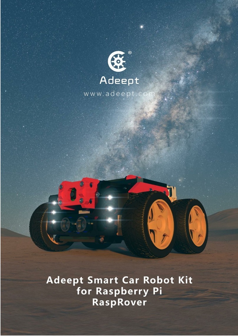
ADEEPT RaspRover User manual
ADEEPT
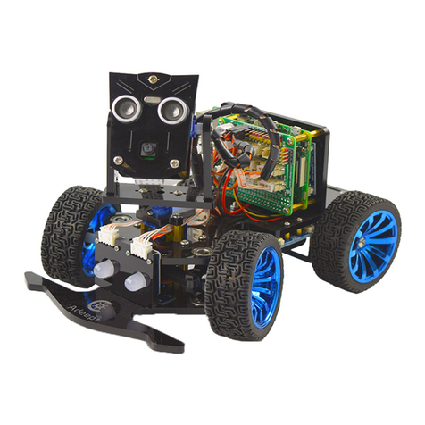
ADEEPT PiCar-B User manual
ADEEPT
ADEEPT Robotic Arm User manual
ADEEPT
ADEEPT PiCar-Pro User manual
ADEEPT
ADEEPT RaspClaws User manual

ADEEPT
ADEEPT Quadruped Robot User manual

ADEEPT
ADEEPT RaspArm User manual

ADEEPT
ADEEPT RaspClaws User manual
ADEEPT
ADEEPT Hexapod User manual
ADEEPT
ADEEPT ADA031 User manual
