CC1020
www.ti.com
SWRS046H –NOVEMBER 2006–REVISED MARCH 2015
RF Transmit (continued)
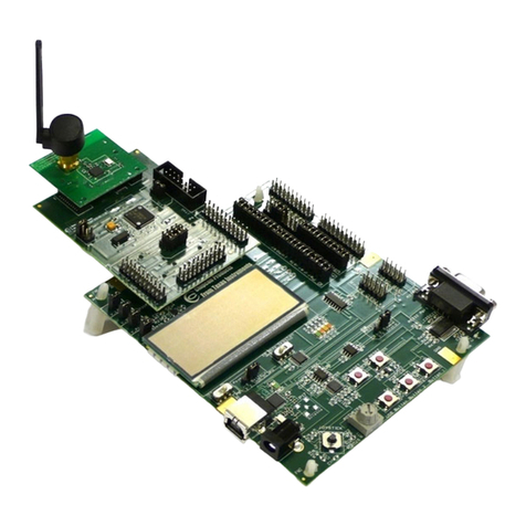
All measurements were performed using the two-layer PCB CC1020EMX reference design. See Figure 6-1. The electrical
specifications given for 868 MHz are also applicable for 902 to 928 MHz. TA= 25°C, AVDD = DVDD = 3.0 V,
fC= 14.7456 MHz if nothing else stated.
PARAMETER MIN TYP MAX UNIT CONDITION
47 to 74, 87.5 to 118, 174 to At maximum output power, +10/+5 dBm
–54 dBm
230, 470 to 862 MHz at 433/868 MHz.
To comply with EN 300 220, FCC
9 kHz to 1 GHz –36 dBm CFR47 part 15 and ARIB STD-T96 an
external (antenna) filter, as implemented
in the application circuit in Section 5.11,
must be used and tailored to each
individual design to reduce out-of-band
spurious emission levels.
Spurious emissions can be measured as
EIRP values according to EN 300 220.
The antenna (SMAFF-433 and SMAFF-
Spurious emission, 868 from R.W. Badland) plays a part in
radiated CW attenuating the spurious emissions.
1 to 4 GHz –30 dBm If the output power is increased using an
external PA, a filter must be used to
attenuate spurs below 862 MHz when
operating in the 868 MHz frequency
band in Europe. Application Note AN036
CC1020/1021 Reducing Spurious
Emission (SWRA057) presents and
discusses a solution that reduces the TX
mode spurious emission close to 862
MHz by increasing the REF_DIV from 1
to 7.
433 MHz 54 + j44 Ω
Optimum load Transmit mode. For matching details see
868 MHz 15 + j24 Ω
impedance Section 5.11.
915 MHz 20 + j35 Ω
4.5 RF Receive
All measurements were performed using the two-layer PCB CC1020EMX reference design. See Figure 6-1. The electrical
specifications given for 868 MHz are also applicable for 902 to 928 MHz. TA= 25°C, AVDD = DVDD = 3.0 V,
fC= 14.7456 MHz if nothing else stated.
PARAMETER MIN TYP MAX UNIT CONDITION
12.5 kHz channel spacing, optimized Sensitivity is measured with PN9
–114 dBm
selectivity, ±2.025 kHz freq. deviation sequence at BER = 10−3
12.5 kHz channel spacing:
12.5 kHz channel spacing, optimized
Receiver sensitivity, –118 dBm 2.4 kBaud, Manchester coded data.
sensitivity, ±2.025 kHz freq. deviation
433 MHz, FSK 25 kHz channel spacing:
25 kHz channel spacing –112 dBm 4.8 kBaud, NRZ coded data, ±2.475
kHz frequency deviation.
500 kHz channel spacing –96 dBm 500 kHz channel spacing:
12.5 kHz channel spacing, ±2.475 kHz 153.6 kBaud, NRZ coded data, ±72
–116 dBm
freq. deviation kHz frequency deviation.
Receiver sensitivity, See Table 5-6 and Table 5-7 for
25 kHz channel spacing –111 dBm
868 MHz, FSK typical sensitivity figures at other
500 kHz channel spacing –94 dBm data rates.
2.4 kBaud –116 dBm Sensitivity is measured with PN9
Receiver sensitivity, sequence at BER = 10−3
433 MHz, OOK 153.6 kBaud –81 dBm Manchester coded data.
4.8 kBaud –107 dBm
Receiver sensitivity, See Table 5-14 for typical sensitivity
868 MHz, OOK figures at other data rates.
153.6 kBaud –87 dBm
Saturation FSK: Manchester/NRZ coded data
(maximum input FSK and OOK 10 dBm OOK: Manchester coded data
level) BER = 10−3
The receiver channel filter 6 dB
System noise bandwidth is programmable from
9.6 to 307.2 kHz
bandwidth 9.6 kHz to 307.2 kHz. See
Section 5.9.2.
Copyright © 2006–2015, Texas Instruments Incorporated Specifications 9
Submit Documentation Feedback
Product Folder Links: CC1020
