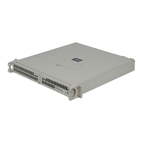
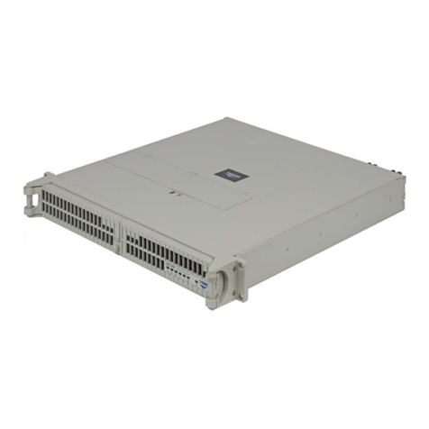
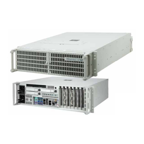
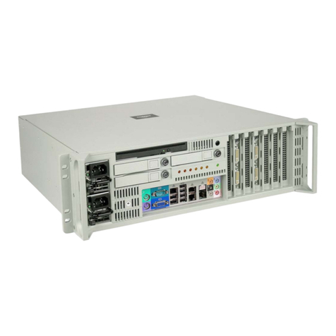
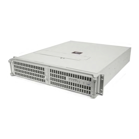
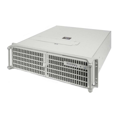
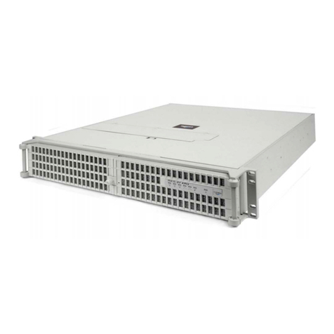
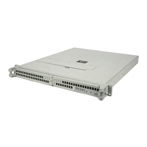
Themis RES-XR4-1U User manual

User Manual
User Manual
Installation
Manual
Installation
Manual
1RU 19” Rack-Mount Rugged Enterprise Server
Supporting X9DRW, X9DBU and X9SCi Motherboards
RES-XR4-1U
Ve rs i o n 1.5
Pa r t N u m b e r : 119708 - 024

Supporting X9DRW, X9DBU and X9SCi Motherboards
RES-XR4-1U
RES-XR4-1U
Supporting X9DRW, X9DBU and X9SCi Motherboards
RES-XR4-1U
RES-XR4-1U
Supporting X9DRW, X9DBU and X9SCi Motherboards
RES-XR4-1U
RES-XR4-1U
Supporting X9DRW, X9DBU and X9SCi Motherboards
RES-XR4-1U
RES-XR4-1U
Supporting X9DRW, X9DBU and X9SCi Motherboards
RES-XR4-1U
RES-XR4-1U
Supporting X9DRW, X9DBU and X9SCi Motherboards
RES-XR4-1U
RES-XR4-1U
Supporting X9DRW, X9DBU and X9SCi Motherboards
RES-XR4-1U
RES-XR4-1U
Supporting X9DRW, X9DBU and X9SCi Motherboards
RES-XR4-1U
RES-XR4-1U
version
1.5
version
1.5
version
1.5
version
1.5
version
1.5
version
1.5
version
1.5
version
1.5

Themis Computer—Rest of World
5 Rue Irene Joliot-Curie
38320 Eybens, France
Phone +33 476 14 77 80
Fax +33 476 14 77 89
Themis Computer—Americas and Pacific Rim
47200 Bayside Parkway
Fremont, CA 94538
Phone (510) 252-0870
Fax (510) 490-5529
World Wide Web http://www.themis.com
RES-XR4-1UInstallationManual*
Version 1.5—June2014
* Supports SuperMicro X9DRW, X9DBU, and X9SCi Motherboards.

Copyright © 2014 Themis Computer, Inc.
ALL RIGHTS RESERVED. No part of this publication may be reproduced in any form, by
photocopy, microfilm, retrieval system, or by any other means now known or hereafter invented without
the prior written permission of Themis Computer.
The information in this publication has been carefully checked and is believed to be accurate. However,
Themis Computer assumes no responsibility for inaccuracies. Themis Computer retains the right to
make changes to this publication at any time without prior notice. Themis Computer does not assume
any liability arising from the application or use of this publication or the product(s) described herein.
RESTRICTED RIGHTS LEGEND: Use, duplication, or disclosure by the United States Government
is subject to the restrictions set forth in DFARS 252.227-7013 (c)(1)(ii) and FAR 52.227-19.
TRADEMARKS and SERVICEMARKS
Themis®is a registered trademark of Themis Computer, Inc.
Intel® and Xeon®are registered trademarks of Intel Corporation.
Red Hat®is a registered trademark of Red Hat, Inc.
Linux®is a registered trademark of Linus Torvalds.
SuperMicro®and SuperDoctor™ are registered trademarks of Super Micro Computer, Inc.
All other trademarks, servicemarks, or registered trademarks used in this publication are the property of
their respective owners.
CE Marking
This product complies with the European EMC Directive (2004/108/EC) and the European Low Voltage
Safety Directive (2006/95/EC)/.
Safety Precautions
Instructions regarding safety precautions during installation, operation, or maintenance of the equipment
are given in the section entitled “Safety Instructions” on page v.
WARNINGS and CAUTIONS
The definitions of WARNINGS and CAUTIONS as used in this document are given in the Preface in
the section entitled “Notes, Cautions, Warnings, and Sidebars”.
RES-XR4-1U Installation Manual, Version 1.5
June 2014
Part Number: 119708-024
Themis Customer Support
North America, South America, and Pacific Rim
Telephone: 510-252-0870
Fax: 510-490-5529
E-mail: support@themis.com
Web Site: http://www.themis.com
iii
Themis Computer
RES-XR4-1U Installation Manual
VersionRevisionHistory
Version 1.5 ....................................................................................... June 2014
• Added German translation to the safety section of this manual
• minor edits and changes throughout this manual
Version 1.4 .................................................................................. January 2014
• Updated the Safety section of the manual
• Updated shock specification to 30 g
• Corrected improper roman numeral page numbering
• Updated all Xeon™ specs to reflect the V2 series (where applicable)
• Updated specs in table 1-1
• Corrected information in table 1-2
• Corrected the front panel LED colors in figure 1-4
• Corrected the icon for the “off state” in table 1-4
• Corrected table 1-5 to properly correlate I/O to correct motherboard
• Corrected all references to 38-mm fans (proper size is 40-mm)
• Added complete BMC section detailing both Renesas and WPCM450R
• Updated table 1-6 to include missing specifications
• Updated electrical table 1-7
• Updated table 1-8 to include more RES-XR4 systems
• Updated table 2-1 to reflect new memory specifications for X9DRW
• Added notes throughout the manual regarding proper battery disposal
• Updated figure 2-16 to include drive/drive tray installation procedure
• Added section in Chapter 3 for BIOS Error Beep Codes
• Added section in Chapter 3 for BIOS Recovery
• Added section for UID in Appendix A
• Added torque spec (20-inch lbs) for the rack slides in Appendix B
• minor edits and updates throughout this manual

iv Themis Computer
RES-XR4-1U Installation Manual Version 1.5
Version 1.3.................................................................................. October 2013
• Added Power Supply Monitoring section in Chapter 1.
Version 1.2.................................................................................. October 2013
• Updated Specs and DC power supply information, and added version 2 CPU
information.
Version 1.1....................................................................................August 2013
• Added all available and planned motherboard configurations as of this date.
Version 1.0.....................................................................................March 2013
• Initial Release

v
Themis Computer
RES-XR4-1U Installation Manual
Safety Instructions
Safety Instructions
To maximize user safety and ensure correct device operation, all instructions con-
tained in this section should be read carefully.
WARNING: All equipment connected to the product must conform to their standards
WARNING: This Themis PRODUCT must be used in sheltered environments only, and
at an altitude of less than 3048 meters (10,000 ft).
• The device must be used in accordance with the instructions for use.
• Electrical installations in the room must correspond to the requirements of
respective regulations.
• Take care that there are no cables, particularly mains cables, in areas where
persons can trip over them.
• Do not use a mains connection in sockets shared by a number of other power
consumers. Do not use an extension cable.
• Only use the mains cable supplied.
• Power cord requirements:
Europe: A power supply unit operating at a nominal voltage of 240V must use
a power cord rated for a minimum operating voltage of 200V and is not to be
used with an operational voltage below 200V
USA: A power supply unit operating at a nominal voltage of 120V must use a
power cord rated for a minimum operating voltage of 100V and is not to be
used with an operational voltage below 100V
Caution: It is important that the user observe all warnings and instructions
that are on the device and contained in this manual.
Caution: The protection of the building serves as protection for the equip-
ment.
Caution: When rack mounted, never lean on the server. It is prohibited to lean
on the server while it is pulled on slide rails (telescopic rails) outside of the
rack (bay). Personal injury and equipment damage can occur.

vi Themis Computer
RES-XR4-1U Installation Manual Version 1.5
• The AC input rating for the 750W (max) power supply units are as follows:
100-240 VAC, 12-6A, 47/63 Hz.
• The unit is completely disconnected from the power source only when all
power cords are disconnected from the power source. Therefore the power
cord(s) and its connectors must always remain easily accessible.
• Do not set up the device in the proximity of heat sources or in a damp location.
Make sure the device has adequate ventilation.
• Manufacturer recommended ambient temperature is 21°C
• All connection cables must be screwed or locked to the chassis housing.
• The device is designed to be used in horizontal position only.
• The device is no longer safe to operate when
— the device has visible damage or
— the device no longer functions.
• In these cases, the device must be shut down and secured against unintentional
operation.
• Repairs/service may only be carried out by a Themis Computer qualified ser-
vice technician.
• Do not open the chassis, or perform services/repairs when the equipment is
powered on, due to electrical shock hazard.
• The device may only be opened for the installation and removal of extension
(PCI) cards, memory modules, storage drives, fan housings, power supplies,
and the lithium battery—all in accordance with the instructions given in this
manual.
• If extensions are made to the device, the legal stipulations and the device spec-
ifications must be observed.
• The device must be switched off when removing the top cover; for example,
before installing extension (PCI) cards.
Operation of Laser Source Devices
DVD/CD-ROM drives contain laser light-emitting diodes (classified in accordance
with IEC 825-1:1993: LASER CLASS 1) and, therefore, must not be opened.
If the enclosure of such a drive is opened, invisible laser radiation is emitted. Do

vii
Themis Computer
RES-XR4-1U Installation Manual
Safety Instructions
not allow yourself to be exposed to this radiation.
The laser system meets the code of Federal Regulations 21 CFR,1040 for the USA
and Canadian Radiation Emitting Devices Act, REDR C 1370.
Electrostatic Discharge (ESD)
A sudden discharge of electrostatic electricity can destroy static-sensitive devices
or micro-circuitry. Proper packaging and grounding techniques are necessary pre-
cautions to prevent damage. Always take the following precautions:
1. Transport boards in static-safe containers such as boxes or bags.
2. Keep electrostatic-sensitive parts in their containers until they arrive at static-
free stations.
3. Always be properly grounded when touching a sensitive board, component, or
assembly.
4. Store electrostatic-sensitive boards in protective packaging or on conductive
foam.
Grounding Methods
Finnish: laite on liitettävä suoja maadoituskoskettimilla varustettuun pistorasiaan
Norwegian: Apparatet må tilkoples jordet stikkontakt
Swedish: Apparaten skall anslutas till jordat uttag
Guard against electrostatic damage at workstations by following these steps:
1. Cover workstations with approved anti-static material. Provide a wrist strap
connected to a work surface and properly grounded tools and equipment.
2. Use anti-static mats, heel straps, or air ionizers to give added protection.
3. Provide a wrist strap connected to a work surface and properly ground tools and
equipment.
4. Handle electrostatic-sensitive components, boards, and assemblies by the case
or the PCB edge.
5. Avoid contact with pins, leads, or circuitry.

viii Themis Computer
RES-XR4-1U Installation Manual Version 1.5
6. Turn off power and input signals before inserting and removing connectors or
test equipment. Power is not considered off until all power supplies have been
disconnected.
7. Keep the work area free of non-conductive materials such as ordinary plastic as-
sembly aids and Styrofoam.
8. Use field service tools, such as cutters, screwdrivers, and vacuums that are con-
ductive.
9. Always place drives and boards PCB-assembly-side down on the foam.
10. Grounding wire size shall be no less than 16 AWG.
11. Overcurrent Protection relies on proper building installation and Earth connec-
tion (ground).
12. High Voltage; Earth connection is essential before connecting the power supply
units
Instructions for the Lithium Battery
Systems are equipped with a lithium battery installed on the motherboard. To
replace this battery, please observe the instructions that are described in this man-
ual.
Follow all local guidelines and regulations for disposing of used batteries .
Warning: There is a danger of explosion when the wrong type of battery is used
as a replacement.
Warning: There is a danger of explosion if attempting to recharge the lithium
battery installed on the motherboard.
Note: Switzerland: Annex 4.10 of SR 814.013 applies to standard batteries.

ix
Themis Computer
RES-XR4-1U Installation Manual
Safety Instructions
European Union Waste Disposal
This section is for waste disposal by users in private households in the European Union.
For all others, please follow all local and government guidelines in accordance with waste disposal and
the symbol seen below.
This symbol on the product or on its packaging indicates that this product must not be
disposed of with your other household waste. Instead, it is your responsibility to
dispose of your waste equipment by handing it to a designated collection point for
the recycling of electrical and electronic equipment. The separate collection and
recycling of your waste equipment at the time of disposal help to conserve natural
resources and ensure recycling respectful of the environment and human health. For
more information on the recycling center nearest your home, contact the town hall,
the household waste disposal service or the shop where you purchased the product.

xThemis Computer
RES-XR4-1U Betriebshandbuch Version 1.5
Sicherheitshinweise
Lesen Sie im Interesse Ihrer eigenen Sicherheit und des bestimmungsgemäßen
Gebrauchs diesen Abschnitt sorgfältig durch.
Warnhinweis: Alle Geräte, die an das Produkt angeschlossen werden, müssen ihren
Standards entsprechen.
Warnhinweis: Dieses THEMIS-Produkt darf nur in geschützten Umgebungen und in
einer Höhe von weniger als 3.048 Metern (10.000 ft) eingesetzt werden
• Das Gerät darf nur entsprechend der Gebrauchsanweisung verwendet
werden.
• Die elektrische Installation im Raum muss den geltenden Vorschriften entspre-
chen.
• Kabel (insbesondere Netzkabel) dürfen nicht in Bereichen verlegt werden, in
denen Personen darüber stolpern können.
• Für den Netzanschluss dürfen keine Verteilerdosen benutzt werden, an die
noch andere Stromverbraucher angeschlossen sind. Verwenden Sie keine
Verlängerungskabel.
• Verwenden Sie nur das mitgelieferte Netzkabel.
• Anforderungen an das Netzkabel:
Europa: Ein Netzteil mit einer Nennspannung von 240 V muss ein Netzkabel
für eine Mindestbetriebsspannung von 200 V benutzen und darf nicht mit einer
Betriebsspannung unter 200 V verwendet werden.
Achtung: Die Warnungen und Hinweise auf dem Gerät und in dieser Anleitung
sind unbedingt zu beachten.
Achtung: Der Schutz des Gebäudes dient zum Schutz der Ausrüstung.
Achtung: Wenn der Rahmen montiert ist, nie auf dem Server aufstützen. Es ist
untersagt, sich auf dem Server aufzustützen, während er auf Gleitschienen (Te-
leskopschienen) außerhalb des Rahmens (Gestells) gezogen wird. Dies kann zu
Personenschäden und zur Beschädigung des Geräts führen.

xi
Themis Computer
RES-XR4-1U Betriebshandbuch
Sicherheitshinweise
USA: Ein Netzteil mit einer Nennspannung von 120 V muss ein Netzkabel für
eine Mindestbetriebsspannung von 100 V benutzen und darf nicht mit einer
Betriebsspannung unter 100 V verwendet werden
• Die AC-Eingangleistungen für 750 W (max.) Netzteile lauten wie folgt:100-
240 VAC, 12-6 A, 47/63 Hz.
• Die vollständige Trennung des Gerätes von der Netzspannung ist nur
gewährleistet, wenn das Netzkabel vom Netz getrennt wird. Aus diesem
Grund muss das Netzkabel samt seinen Anschlüssen jederzeit leicht zugän-
glich sein.
• Das Gerät darf nicht in der Nähe von Wärmequellen oder an einem feuchten
Ort aufgestellt werden. Achten Sie auf eine ausreichende Belüftung des
Gerätes.
• Alle Stecker an den Verbindungskabeln müssen am Gehäuse festgeschraubt
oder festgeklemmt sein.
• Das Gerät darf nur in horizontaler Lage betrieben werden.
• Die Betriebssicherheit des Gerätes ist nicht mehr gewährleistet, wenn
— das Gerät sichtbare Beschädigungen aufweist oder
— das Gerät nicht mehr funktioniert.
• In diesen Fällen muss das Gerät ausgeschaltet und gegen unbeabsichtigte
Inbetriebnahme gesichert werden.
• Reparaturen dürfen nur von Beauftragten der Firma Themis Computer durch-
geführt werden.
• Das Öffnen des Gerätes ist nur zulässig für den Ein- und Ausbau von Erweit-
erungskarten (PCI), Speichermodulen, Festplatten, Lüftergehäusen, Netz-
teilen und der Lithiumbatterie – entsprechend den Anweisungen in dieser
Anleitung.
• Bei einer Erweiterung des Gerätes sind die gesetzlichen Bestimmungen und
die Gerätespezifikationen zu beachten.
• Vor Abnehmen des Deckels, z.B. für den Einbau von Erweiterungskarten
(PCI), erst das Gerät ausschalten.
Betrieb von Lasergeräten
DVD/CD-ROM-Laufwerke enthalten Laserdioden (Klassifizierung gemäß IEC
825-1:1993: LASERKLASSE 1) und dürfen deshalb nicht geöffnet werden.
Beim Öffnen des Laufwerkgehäuses tritt unsichtbare Laserstrahlung aus. Setzen

xii Themis Computer
RES-XR4-1U Betriebshandbuch Version 1.5
Sie sich dieser Strahlung keinesfalls aus.
Das Lasersystem erfüllt die Anforderungen des Code of Federal Regulations 21
CFR,1040 (für die USA) und des Canadian Radiation Emitting Devices Act,
REDR C 1370 (für Kanada).
Elektrostatische Entladung (ESD)
Eine plötzliche elektrostatische Entladung kann empfindliche Geräte oder Mikros-
chaltungen zerstören. Dem ist durch ordnungsgemäße Verpackung und Erdung
unbedingt vorzubeugen. Die folgenden Vorsichtsmaßnahmen sind jederzeit zu
beachten:
1. Transportieren Sie Platinen in elektrostatisch sicheren Behältern oder Taschen.
2. Belassen Sie elektrostatisch empfindliche Bauteile bis zum Eintreffen an einem
antistatischen Ort in ihrem Behälter.
3. Achten Sie beim Berühren empfindlicher Platinen, Bauteile oder Baugruppen
stets auf eine gute Eigenerdung.
4. Lagern Sie elektrostatisch empfindliche Platinen in Schutzverpackungen oder
auf leitfähigem Schaumstoff.
Erdungsmethoden
Die folgenden Maßnahmen schützen vor elektrostatischen Schäden am Arbe-
itsplatz:
1. Legen Sie am Arbeitsplatz geeignete Antistatikmatten aus. Tragen Sie ein Er-
dungsarmband, das mit dem Arbeitsplatz verbunden ist, und verwenden Sie nur
ausreichend geerdete Arbeitsmittel.
2. Verwenden Sie als zusätzlichen Schutz geeignete Antistatikfußmatten, Fersen-
bänder oder Luftionisatoren.
3. Fassen Sie elektrostatisch empfindliche Bauteile, Platinen und Baugruppen nur
am Gehäuse oder am Rand an.
4. Vermeiden Sie den Kontakt mit Stiften, Leitungen und Leiterbahnen.
5. Schalten Sie vor dem Anschließen und Trennen von Steckverbindern oder Prüf-
geräten alle Spannungs- und Signalquellen aus.

xiii
Themis Computer
RES-XR4-1U Betriebshandbuch
Sicherheitshinweise
6. Verwenden Sie am Arbeitsplatz keine nichtleitenden Materialien, wie gewöhn-
liche Kunststoffmontagehilfen oder Styropor.
7. Benutzen Sie leitende Werkzeuge (z.B. Messer, Schraubendreher und Staubsau-
ger).
8. Legen Sie Laufwerke und Platinen immer mit der Bauteilseite nach unten auf
die Schaumstoffunterlage.
9. Die Größe der Erdungsleitung sollte nicht weniger als 16 AWG betragen.
10. Überstromschutz ist auf ordnungsgemäße Gebäudeinstallation und richtigen
Erdungsanschluss (Masse) angewiesen.
11. Hochspannung: Der Erdungsanschluss muss stimmen, bevor die Netzteile an-
geschlossen werden.
Hinweise zur Lithiumbatterie
Auf dem Motherboard von RES-Systemen befindet sich eine Lithiumbatterie.
Beim Wechseln dieser Batterie sind die entsprechenden Hinweise in dieser Anlei-
tung zu beachten.
Vorsicht: Beim Einbau einer Ersatzbatterie des falschen Typs besteht Explo-
sionsgefahr.

xiv Themis Computer
RES-XR4-1U Betriebshandbuch Version 1.5

xv
Themis Computer
Table of Contents
Version Revision History ...................................................................................................... iii
Safety Instructions...................................................................................................................v
Preface................................................................................................................................. xxix
1. Overview and Specifications ........................................................................................ 1-1
1.1 Overview ................................................................................................................ 1-1
1.1.1 External Features ....................................................................................... 1-3
1.2 Front Panel and System LEDs ............................................................................... 1-5
1.3 Rear Panel I/O ........................................................................................................ 1-8
1.4 Block Diagrams ................................................................................................... 1-11
1.5 Internal Views ...................................................................................................... 1-14
1.6 Processor and Chipset Overview ......................................................................... 1-17
1.6.1 C602/C606 Chipset .................................................................................. 1-17
1.6.2 Main Features of the E5-2400/E5-2600 Series Processor and C602/
C606 Chipset ............................................................................................ 1-17
1.6.3 C204 Chipset ............................................................................................ 1-18
1.6.4 Main Features of the E3-1200 Series Processor and C204 Chipset ........ 1-19
1.7 Special Features ................................................................................................... 1-19
1.7.1 Recovery from AC Power Loss ............................................................... 1-19
1.7.2 PC Health Monitoring .............................................................................. 1-19
1.7.2.1 Fan Status Monitor .................................................................... 1-20
1.7.2.2 Environmental Temperature Control ........................................ 1-20
1.7.2.3 System Resource Alert .............................................................. 1-20
1.7.3 Power Supply Monitoring ........................................................................ 1-20
1.7.3.1 I2C Notes .................................................................................. 1-21
1.7.3.2 Sample I2C Commands ............................................................ 1-21
1.7.4 ACPI Features .......................................................................................... 1-22
1.7.5 Slow Blinking LED for Suspend-State Indicator ....................................1-22
1.7.6 Super I/O .................................................................................................. 1-22
1.7.7 Overview of the Renesas SH7757 ........................................................... 1-22

xvi Themis Computer
RES-XR4-1U Installation Manual Version 1.5
1.7.7.1 BMC Subsystem Features ......................................................... 1-23
1.7.8 Overview of the Nuvoton WPCM450 BMC ........................................... 1-23
1.7.8.1 WPCM450R DDR2 Memory Interface ....................................1-24
1.7.8.2 WPCM450R PCI System Interface .......................................... 1-24
1.7.8.3 Other Features of the WPCM450 BMC Controller .................. 1-24
1.8 Specifications ....................................................................................................... 1-26
1.8.1 General ..................................................................................................... 1-26
1.8.2 Electrical .................................................................................................. 1-27
1.8.2.1 System Power ........................................................................... 1-27
1.8.2.2 Output Voltage .......................................................................... 1-28
1.8.3 Environmental .......................................................................................... 1-28
1.8.3.1 Shock ........................................................................................ 1-28
1.8.3.2 Electrostatic Discharge ............................................................. 1-28
1.8.3.3 Noise ......................................................................................... 1-28
1.9 Packaging and Shipping ....................................................................................... 1-29
1.9.1 Accessory Kit ........................................................................................... 1-29
1.10 Rack-Mount Slides (Optional) .............................................................................1-30
1.11 RES System ......................................................................................................... 1-31
2. Installation and Operation ........................................................................................... 2-1
2.1 Installation Procedures ........................................................................................... 2-1
2.1.1 Remove Protective Top Cover ................................................................... 2-1
2.1.2 Memory Modules ....................................................................................... 2-3
2.1.2.1 Memory Module Location .......................................................... 2-6
2.1.2.2 Installation .................................................................................. 2-9
2.1.3 PCI Cards ................................................................................................. 2-11
2.1.3.1 Installing Cards ......................................................................... 2-12
2.1.4 Lithium Battery ........................................................................................ 2-15
2.1.4.1 Removing the Lithium Battery ................................................. 2-15
2.1.4.2 Installing a Lithium Battery ......................................................2-16
2.1.5 Storage Drive ........................................................................................... 2-17
2.1.5.1 Opening the RES-XR4-1U Front Doors ...................................2-17
2.1.5.2 Storage-Drive Removal ............................................................ 2-18
2.1.5.3 Storage Drive Installation .........................................................2-20
2.1.6 Cooling Fans ............................................................................................ 2-20
2.1.6.1 Removing and Installing the 40-mm Fan Assembly ................ 2-20
2.2 Power Supply ....................................................................................................... 2-22

xvii
Themis Computer
Table of Contents
2.2.1 DC Power Supply Option ........................................................................ 2-22
2.2.2 Removing a Power Supply ...................................................................... 2-23
2.2.2.1 Chassis Grounding Screw ......................................................... 2-25
2.2.3 Installing a Power Supply ........................................................................ 2-26
2.2.4 Installing a Power Cord Retention Bracket ............................................. 2-27
2.2.5 Installing a USB Cable Retention Bracket .............................................. 2-29
2.3 Rack Mounts ........................................................................................................ 2-30
2.3.1 Mounting Brackets ................................................................................... 2-30
2.3.2 Rack-Mount Slides (Optional) ................................................................. 2-30
2.4 Operation ............................................................................................................. 2-31
2.4.1 Plugging in the AC Power Cords ............................................................. 2-31
2.4.2 Turning the System On ............................................................................ 2-31
2.4.3 Getting Started ......................................................................................... 2-32
2.4.3.1 Configuration ............................................................................ 2-32
2.4.3.2 Linux Installation ...................................................................... 2-32
2.4.4 Turning the System Off ........................................................................... 2-32
3. BIOS Setup Utility ........................................................................................................ 3-1
3.1 Introduction ............................................................................................................ 3-1
3.1.1 Starting BIOS Setup Utility ....................................................................... 3-1
3.1.2 How To Change the Configuration Data ................................................... 3-2
3.1.3 Starting the Setup Utility ........................................................................... 3-2
3.2 Main BIOS Setup ................................................................................................... 3-3
3.2.1 System Overview ....................................................................................... 3-3
3.2.1.1 System Time/System Date .......................................................... 3-3
3.2.1.2 AMI BIOS ................................................................................... 3-4
3.2.1.3 Processor ..................................................................................... 3-4
3.2.1.4 System Memory .......................................................................... 3-4
3.3 Advanced Setup Configuration .............................................................................. 3-4
3.3.1 BOOT Features .......................................................................................... 3-5
3.3.1.1 Quiet Boot ................................................................................... 3-5
3.3.1.2 AddOn ROM Display Mode ....................................................... 3-5
3.3.1.3 Bootup Num-Lock ...................................................................... 3-5
3.3.1.4 Wait For 'F1' If Error .................................................................. 3-6
3.3.1.5 Interrupt 19 Capture .................................................................... 3-6
3.3.2 Power Configuration .................................................................................. 3-6
3.3.2.1 Watch Dog Function ................................................................... 3-6

xviii Themis Computer
RES-XR4-1U Installation Manual Version 1.5
3.3.2.2 Power Button Function ............................................................... 3-6
3.3.2.3 Restore on AC Power Loss ......................................................... 3-6
3.3.3 CPU Configuration .................................................................................... 3-6
3.3.3.1 Socket 1 CPU Information/Socket 2 CPU Information .............. 3-7
3.3.3.2 CPU Speed .................................................................................. 3-7
3.3.3.3 Clock Spread Spectrum .............................................................. 3-7
3.3.3.4 Hyper-threading .......................................................................... 3-7
3.3.3.5 Active Processor Cores ............................................................... 3-7
3.3.3.6 Limit CPUID Maximum .............................................................3-8
3.3.3.7 Execute-Disable Bit Capability ................................................... 3-8
3.3.3.8 Intel®AES-NI ............................................................................. 3-8
3.3.3.9 Hardware Prefetcher .................................................................... 3-8
3.3.3.10 Adjacent Cache Line Prefetcher .................................................. 3-8
3.3.3.11 DCU Streamer Prefetcher ............................................................ 3-8
3.3.3.12 DCU IP Prefetcher ...................................................................... 3-8
3.3.3.13 Intel Virtualization Technology................................................... 3-9
3.3.4 CPU Power Management Configuration ...................................................3-9
3.3.4.1 Power Technology ...................................................................... 3-9
3.3.5 Chipset Configuration .............................................................................. 3-11
3.3.5.1 NorthBridge Configuration ....................................................... 3-11
3.3.5.2 QPI (Quick Path Interconnect) Configuration .......................... 3-12
3.3.5.3 DIMM Configuration ................................................................ 3-13
3.3.5.4 DIMM Information ................................................................... 3-13
3.3.5.5 SouthBridge Configuration ....................................................... 3-15
3.3.6 SATA Configuration ................................................................................ 3-16
3.3.6.1 SATA Port0~SATA Port5 ........................................................ 3-16
3.3.6.2 SATA Mode .............................................................................. 3-16
3.3.7 SCU (Storage Control Unit) Configuration ............................................. 3-17
3.3.7.1 Storage Controller Unit ............................................................. 3-17
3.3.7.2 OnChip SCU Option ROM ....................................................... 3-18
3.3.7.3 SCU Port 0-SCU Port 7 ............................................................ 3-18
3.3.8 PCIe/PCI/PnP Configuration ................................................................... 3-18
3.3.8.1 PCI ROM Priority .....................................................................3-18
3.3.8.2 PCI Latency Timer .................................................................... 3-18
3.3.8.3 Above 4G Decoding .................................................................. 3-18
3.3.8.4 PERR# Generation .................................................................... 3-18
3.3.8.5 SERR# Generation .................................................................... 3-18
3.3.8.6 Maximum Payload .................................................................... 3-19
Table of contents
Other Themis Server manuals

Themis
Themis RES-21XR3 User manual

Themis
Themis RES-22XR3 User manual

Themis
Themis RES-32XR3/FIO User manual

Themis
Themis RES-22XR3 User manual

Themis
Themis RES-12XR3 User manual

Themis
Themis RES-12XR3-S User manual

Themis
Themis RES-32DCX User manual

Themis
Themis CoolShell CS-3U User manual

Themis
Themis RES-32XR3-S User manual

Themis
Themis RES-32XEL User manual

Themis
Themis RES - 32XR3 User manual

Themis
Themis RES-32XR3-S User manual

Themis
Themis RES-22DCX User manual

Themis
Themis CoolShell 3U User manual

Themis
Themis CS-5U User manual

Themis
Themis RES-11XR3 User manual

Themis
Themis RES-XR4-3U User manual

Themis
Themis RES-22XR3 User manual

Themis
Themis 200 User manual

Themis
Themis RES-12DCX User manual