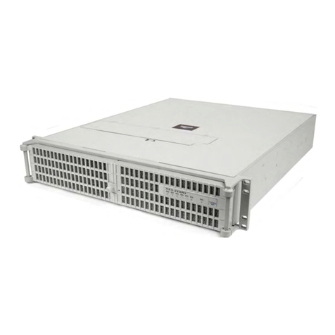
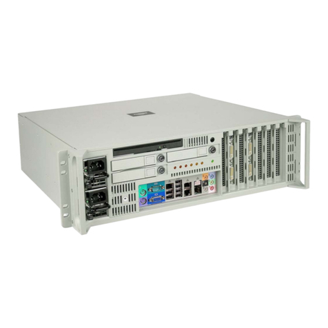
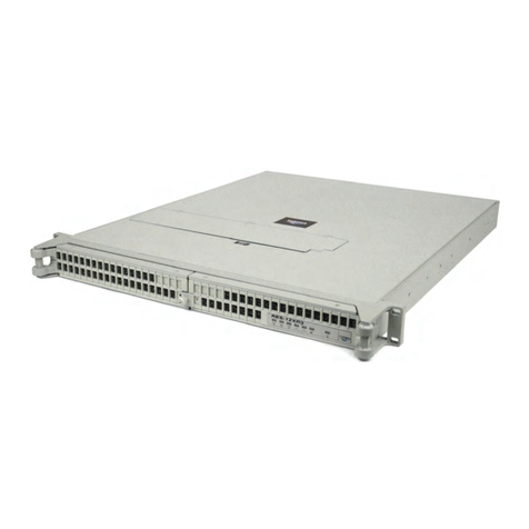
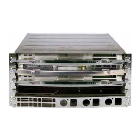
Themis CoolShell CS-3U User manual

User Manual
User Manual
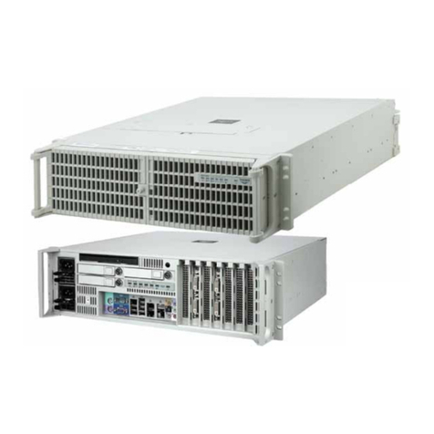
Multiple-CPU, Multiple-Core 64-bit Scalable Server / Rugged 3U-High Subrack
Removable 1U-High ComponentsCPU & I/O Blades, Media Module, 2 Power Supplies
PCI-Express / SATA / Multiple Gigabit Ethernet, SFP Optical Transceiver, & USB Ports
CoolShell
CS-3U
CoolShell
CS-3U
Installation
Manual
Installation
Manual
™

Multiple-CPU, Multiple-Core 64-Bit Scalable System
CoolShell CS-3U
CoolShell CS-3U
Multiple-CPU, Multiple-Core 64-Bit Scalable System
CoolShell CS-3U
CoolShell CS-3U
Multiple-CPU, Multiple-Core 64-Bit Scalable System
CoolShell CS-3U
CoolShell CS-3U
Multiple-CPU, Multiple-Core 64-Bit Scalable System
CoolShell CS-3U
CoolShell CS-3U
Multiple-CPU, Multiple-Core 64-Bit Scalable System
CoolShell CS-3U
CoolShell CS-3U

Themis Computer—Rest of World
5 Rue Irene Joliot-Curie
38320 Eybens, France
Phone +33 476 14 77 80
Fax +33 476 14 77 89
Themis Computer—Americas and Pacific Rim
47200 Bayside Parkway
Fremont, CA 94538
Phone (510) 252-0870
Fax (510) 490-5529
World Wide Web http://www.themis.com
CoolShellCS-3UInstallationManual
Version 1.1— December 2009

Copyright © 2009 Themis Computer, Inc.
ALL RIGHTS RESERVED. No part of this publication may be reproduced in any form, by
photocopy, microfilm, retrieval system, or by any other means now known or hereafter invented without
the prior written permission of Themis Computer.
The information in this publication has been carefully checked and is believed to be accurate. However,
Themis Computer assumes no responsibility for inaccuracies. Themis Computer retains the right to
make changes to this publication at any time without prior notice. Themis Computer does not assume
any liability arising from the application or use of this publication or the product(s) described herein.
RESTRICTED RIGHTS LEGEND: Use, duplication, or disclosure by the United States Government
is subject to the restrictions set forth in DFARS 252.227-7013 (c)(1)(ii) and FAR 52.227-19.
TRADEMARKS and SERVICEMARKS
Themis®is a registered trademark of Themis Computer, Inc.
CoolShell™and CoolShell CS3U™are trademarks of Themis Computer, Inc.
AMD™, the AMD Arrow logo, AMD Opteron, and combinations thereof are trademarks of Advanced
Micro Devices, Inc.
ATI™is a trademark of Advanced Micro Devices, Inc. (AMD)
AMI®is a registered trademark of AMI Semiconductor, Inc.
HyperTransportTM is a licensed trademark of the HyperTransport Technology Consortium.
GeForce®, nForce®, and nVidia are registered trademarks of NVIDIA corporation.
nVidia®is a registered trademark of NVIDIA corporation.
WinbondTM is a trademark of the Winbond Electronics Corp.
PCI-X®and PCI Express®are registered trademarks of PCI-SIG®Special Interest Group.
Intersil®is a registered trademark of Intersil Americas Inc.
Red Hat®is a registered trademark of Red Hat, Inc.
Linux®is a registered trademark of Linus Torvalds.
All other trademarks, servicemarks, or registered trademarks used in this publication are the property of
their respective owners.
CoolShell CS-3U Installation Manual, Version 1.1
December 2009
Part Number: 116586-024
Themis Customer Support
North America, South America, and Pacific Rim
Telephone: 510-252-0870
Fax: 510-490-5529
E-mail: support@themis.com
Web Site: http://www.themis.com

iii
Themis Computer
CoolShell CS-3U Installation Manual
VersionRevisionHistory
Version 1.1...................................................................................December 2009
• Modified Table 1-1, page 1-6, to change reliability to 16,800 hours, and
Table 1-2, page 1-6, to change vibration to 3G.
• Assorted minor edits and changes throughout the manual.
Version 1.0................................................................................... December 2009

iv Themis Computer
CoolShell CS-3U Installation Manual
Safety Instructions
To maximize user safety and ensure correct device operation, all instructions con-
tained in this section should be read carefully.
• Take care that there are no cables, particularly mains cables, in areas where
persons can trip over them.
• Do not use a mains connection in sockets shared by a number of other power
consumers. Do not use an extension cable.
• Only use the mains cable supplied.
• The unit is completely disconnected from the power source only when the
power cord is disconnected from the power source. Therefore the power cord
and its connectors must always remain easily accessible.
• Do not set up the device in the proximity of heat sources or in a damp location.
Make sure the device has adequate ventilation.
• All plugs on the connection cables must be screwed or locked to the chassis
housing.
• The device is designed to be used in horizontal position only.
• Repairs may only be carried out by a person authorized by Themis Computer.
• If extensions are made to the device, the legal stipulations and the device spec-
ifications must be observed.
• The CoolShell CS-3U power cord(s) should be disconnected before removing
or replacing any CoolShell CS-3U components (Blade or Module).
Caution: It is important that the user observe all warnings and instructions that
are on the device and contained in this manual.

v
Themis Computer
Table of Contents
Preface ....................................................................................................................................xv
1. Overview and Specifications ........................................................................................ 1-1
1.1 Overview—CoolShell CS-3U ................................................................................ 1-1
1.2 Storage Expansion Subsystem ............................................................................... 1-5
1.3 Specifications ......................................................................................................... 1-6
1.3.1 General ....................................................................................................... 1-6
1.3.2 Environmental ............................................................................................ 1-6
1.3.2.1 Shock .......................................................................................... 1-7
1.3.2.2 Electrostatic Discharge ............................................................... 1-7
1.3.2.3 Noise Level ................................................................................. 1-7
1.3.3 Regulatory Compliance ............................................................................. 1-7
1.3.4 RoHS Compliance ..................................................................................... 1-7
1.3.5 Hazardous Materials .................................................................................. 1-8
1.3.6 CPU Blade ................................................................................................. 1-8
1.3.7 I/O Blade .................................................................................................... 1-9
1.4 Packaging and Shipping ....................................................................................... 1-10
2. Installation and Operation ........................................................................................... 2-1
2.1 Installation Procedures ........................................................................................... 2-1
2.1.1 Subrack Installation ................................................................................... 2-1
2.1.2 CoolShell CS-3U Installation .................................................................... 2-3
2.1.3 Multiple Video Displays ............................................................................ 2-5
2.1.4 Audio Connection ...................................................................................... 2-6
2.2 Operation ............................................................................................................... 2-7
2.2.1 Operation with Factory-Installed Linux .................................................... 2-7
Appendix A. Connector Pinouts ...................................................................................... A-1
A.1 CPU Blade ............................................................................................................ A-1
A.1.1 Power & Reset Connector ......................................................................... A-1
A.1.2 PCI-Express Connector ............................................................................. A-2
A.1.3 Clock & I2C Bus Connector (Firewire 1394) ........................................... A-3

vi Themis Computer
CoolShell CS-3U Installation Manual
A.1.4 Stereo Audio Connectors .......................................................................... A-4
A.2 I/O Blade ............................................................................................................... A-5
A.2.1 USB 2.0 Connectors ................................................................................. A-5
A.2.2 DVI Video Output Connector ................................................................... A-5
A.2.3 Stereo Goggle Connector .......................................................................... A-7
A.3 Media Module ....................................................................................................... A-8
A.3.1 Copper Gigabit Ethernet Ports .................................................................. A-8
A.3.2 Optical Gigabit Ethernet Ports .................................................................. A-9
A.3.3 USB 2.0 Connectors ............................................................................... A-10
A.4 Storage Expansion Subsystem ............................................................................ A-11
A.4.1 Power & Reset Connector ....................................................................... A-11
A.4.2 PCI-Express Connector ........................................................................... A-11
A.4.3 Clock & I2C Bus Connector (Firewire 1394) ......................................... A-11
Appendix B. BIOS Setup Utility ......................................................................................B-1
B.1 Introduction ............................................................................................................B-1
B.1.1 System BIOS ..............................................................................................B-1
B.1.2 How To Change the Configuration Data ...................................................B-2
B.1.3 Starting the Setup Utility ...........................................................................B-2
B.2 Running Setup ........................................................................................................B-2
B.3 Main BIOS Setup ...................................................................................................B-3
B.3.1 Main Setup Features ..................................................................................B-4
B.3.1.1 System Time ...............................................................................B-4
B.3.1.2 System Date ................................................................................B-4
B.3.1.3 BIOS Date ...................................................................................B-4
B.3.1.4 Legacy Diskette A ......................................................................B-4
B.3.1.5 IDE Channel 0 Master/Slave, IDE Channel 1
Master/Slave, SATA Port 2, and SATA Port 3 ..........................B-4
B.3.1.6 Parallel ATA ...............................................................................B-5
B.3.1.7 Serial ATA ..................................................................................B-5
B.3.1.8 Native Mode Operation ..............................................................B-5
B.3.1.9 SATA Controller Mode ..............................................................B-5
B.3.1.10 System Memory ..........................................................................B-6
B.3.1.11 Extended Memory .......................................................................B-6
B.4 Advanced Setup .....................................................................................................B-7

vii
Themis Computer
Table of Contents
B.4.1 Boot Features .............................................................................................B-7
B.4.1.1 Quick Boot Mode ........................................................................B-7
B.4.1.2 Quiet Boot Mode ........................................................................B-8
B.4.1.3 POST Errors ................................................................................B-8
B.4.1.4 ACPI Mode .................................................................................B-8
B.4.1.5 Power Button Behavior ...............................................................B-8
B.4.1.6 Resume On Modem Ring ...........................................................B-8
B.4.1.7 Power Loss Control ....................................................................B-8
B.4.1.8 Watch Dog ..................................................................................B-8
B.4.1.9 Summary Screen .........................................................................B-8
B.4.2 Memory Cache ...........................................................................................B-9
B.4.2.1 Cache System BIOS Area ...........................................................B-9
B.4.2.2 Cache Video BIOS Area .............................................................B-9
B.4.2.3 Cache Base 0-512K ....................................................................B-9
B.4.2.4 Cache Base 512K-640K ..............................................................B-9
B.4.2.5 Cache Extended Memory ..........................................................B-10
B.4.2.6 Discrete MTRR Allocation .......................................................B-10
B.4.3 PCI Configuration ....................................................................................B-10
B.4.3.1 Onboard GLAN1/Onboard GLAN2
(Gigabit-LAN) OPROM Configure ..........................................B-10
B.4.3.2 Onboard SCSI OPROM Configure ...........................................B-10
B.4.3.3 PCI Parity Error Forwarding .....................................................B-11
B.4.3.4 Reset Configuration Data ..........................................................B-11
B.4.3.5 Frequency for PCI-X #7, MASS
(Mass Data Storage)/ZCR (Zero Channel RAID) ....................B-11
B.4.3.6 Slot#6 PCI-X 133MHz, Slot E1 x8, Slot E2 x4 and Slot E3 x8 B-11
B.4.4 Advanced Chipset Control .......................................................................B-12
B.4.4.1 SERR Signal Condition ............................................................B-12
B.4.4.2 4GB PCI Hole Granularity .......................................................B-12
B.4.4.3 Memory Branch Mode ..............................................................B-12
B.4.4.4 Branch 0 Rank Interleaving & Sparing .....................................B-12
B.4.4.5 Branch 1 Rank Interleaving & Sparing .....................................B-12
B.4.4.6 Enhanced x8 Detection .............................................................B-13
B.4.4.7 Crystal Beach Features .............................................................B-13
B.4.4.8 Route Port 80h Cycles ..............................................................B-13
B.4.4.9 Clock Spectrum Feature ............................................................B-13
B.4.4.10 Enabling Multi-Media Timer ....................................................B-13
B.4.4.11 USB Function ...........................................................................B-13
viii Themis Computer
CoolShell CS-3U Installation Manual
B.4.4.12 Legacy USB Support ................................................................B-13
B.4.5 Advanced Processor Options ...................................................................B-14
B.4.5.1 CPU Speed ................................................................................B-14
B.4.5.2 Frequency Ratio (Only when supported by the CPU) ..............B-14
B.4.5.3 Hyperthreading (Only when supported by the CPU) ................B-14
B.4.5.4 Core-Multi-Processing (Only when supported by the CPU) ....B-14
B.4.5.5 Machine Checking (Only when supported by the CPU) ..........B-14
B.4.5.6 Thermal Management 2 (Only when supported by the CPU) ..B-14
B.4.5.7 C1 Enhanced Mode (Only when supported by the CPU) .........B-14
B.4.5.8 Execute Disable Bit (Only when supported by the CPU) .........B-15
B.4.5.9 Adjacent Cache Line Prefetch
(Only when supported by the CPU) ..........................................B-15
B.4.5.10 Hardware Prefetch (Only when supported by the CPU) ...........B-15
B.4.5.11 PECI Absent Alarm (Only when supported by the CPU) ........B-15
B.4.5.12 Intel Virtualization Technology
(Only when supported by the CPU) ..........................................B-15
B.4.5.13 Intel EIST Support (Only when supported by the CPU) ..........B-16
B.4.6 I/O Device Configuration ........................................................................B-16
B.4.6.1 KBC Clock Input ......................................................................B-16
B.4.6.2 Serial Port A ..............................................................................B-16
B.4.6.3 Base I/O Address ......................................................................B-16
B.4.6.4 Interrupt ....................................................................................B-16
B.4.6.5 Serial Port B ..............................................................................B-17
B.4.6.6 Mode .........................................................................................B-17
B.4.6.7 Base I/O Address ......................................................................B-17
B.4.6.8 Interrupt ....................................................................................B-17
B.4.6.9 Floppy Disk Controller .............................................................B-17
B.4.6.10 Base I/O Address ......................................................................B-17
B.4.7 DMI Event Logging .................................................................................B-17
B.4.7.1 Event Log Validity ....................................................................B-17
B.4.7.2 Event Log Capacity ..................................................................B-17
B.4.7.3 View DMI Event Log ...............................................................B-18
B.4.7.4 Event Logging ...........................................................................B-18
B.4.7.5 ECC Event Logging ..................................................................B-18
B.4.7.6 Mark DMI Events as Read ........................................................B-18
B.4.7.7 Clear All DMI Event Logs ........................................................B-18
B.4.8 Console Redirection .................................................................................B-18
B.4.8.1 COM Port Address ....................................................................B-18

ix
Themis Computer
Table of Contents
B.4.8.2 BAUD Rate ...............................................................................B-18
B.4.8.3 Console Type ............................................................................B-18
B.4.8.4 Flow Control .............................................................................B-19
B.4.8.5 Console Connection ..................................................................B-19
B.4.8.6 Continue CR after POST ..........................................................B-19
B.4.9 Hardware Monitor Logic [Alternative 1] .................................................B-19
B.4.9.1 CPU Temperature Threshold ....................................................B-19
B.4.9.2 Fan Speed Control Modes .........................................................B-20
B.4.9.3 Voltage Monitoring ...................................................................B-20
B.4.10 Hardware Monitor Logic [Alternative 2] .................................................B-21
B.4.10.1 CPU Temperature Threshold ....................................................B-21
B.4.10.2 Fan Speed Control Modes .........................................................B-21
B.4.10.3 Voltage Monitoring ...................................................................B-21
B.4.11 Hardware Monitor Logic [Alternative 3] .................................................B-22
B.4.11.1 CPU Temperature Threshold ....................................................B-22
B.4.11.2 Temperature Monitoring (If supported by the CPU) ................B-22
B.4.11.3 Fan Speed Control Modes .........................................................B-23
B.4.11.4 Voltage Monitoring ...................................................................B-23
B.4.12 IPMI (Only when an IPMI card is installed) ...........................................B-24
B.4.12.1 IPMI Specification Version ......................................................B-24
B.4.12.2 Firmware Version .....................................................................B-24
B.4.12.3 System Event Logging ..............................................................B-24
B.4.12.4 Clear System Event Logging ....................................................B-25
B.4.12.5 Existing Event Log Number .....................................................B-25
B.4.12.6 Event Log Control ....................................................................B-25
B.4.12.7 BIOS POST Watch Dog ...........................................................B-25
B.4.12.8 OS Boot Watch Dog .................................................................B-25
B.4.12.9 Timer for Loading OS (Minutes) ..............................................B-25
B.4.12.10Time Out Option ......................................................................B-25
B.4.13 System Event Log/System Event Log (List Mode) .................................B-26
B.4.14 Realtime Sensor Data ...............................................................................B-27
B.5 Security Settings ..................................................................................................B-28
B.5.1 Supervisor Password Is: ...........................................................................B-28
B.5.2 User Password Is: .....................................................................................B-29
B.5.3 Set Supervisor Password ..........................................................................B-29
B.5.4 Set User Password ...................................................................................B-29
B.5.5 Password on Boot ....................................................................................B-29

xThemis Computer
CoolShell CS-3U Installation Manual
B.6 Boot Settings ........................................................................................................B-30
B.6.1 Boot Priority Order/Excluded from Boot Orders ....................................B-30
B.7 Exit .......................................................................................................................B-31
B.7.1 Exit Saving Changes ................................................................................B-31
B.7.2 Exit Discarding Changes .........................................................................B-31
B.7.3 Load Setup Defaults .................................................................................B-32
B.7.4 Discard Changes ......................................................................................B-32
B.7.5 Save Changes ...........................................................................................B-32
B.8 BIOS POST Messages .........................................................................................B-33
Appendix C. Red Hat Enterprise Linux Installation .....................................................C-1
C.1 Introduction ............................................................................................................C-1
C.2 Installation .............................................................................................................C-1
C.2.1 BIOS Configuration ...................................................................................C-1
C.2.2 Installing from CD-ROM ...........................................................................C-1
C.2.2.1 Language Selection .....................................................................C-2
C.2.2.2 Keyboard Selection .....................................................................C-3
C.2.2.3 Select Disk Partitioning Setup ....................................................C-3
C.2.2.4 Automatic Partitioning ................................................................C-5
C.2.2.5 Partitioning Your System ............................................................C-6
C.2.2.6 Adding Partitions ........................................................................C-7
C.2.2.7 Boot Loader Configuration .........................................................C-9
C.2.2.8 Advanced Boot Loader Configuration ......................................C-10
C.2.2.9 Network Configuration .............................................................C-11
C.2.2.10 Firewall Configuration ..............................................................C-13
C.2.2.11 Time Zone Configuration .........................................................C-14
C.2.2.12 Set Root Password ....................................................................C-15
C.2.2.13 Package Group Selection ..........................................................C-16
C.2.2.14 Preparing to Install ....................................................................C-18
C.2.2.15 Installing Packages ...................................................................C-18
C.2.2.16 Installation Complete ................................................................C-19
Index ................................................................................................................Index-1
Reader Comment Card

xi
Themis Computer
Table of Contents
List of Figures
Figure 1-1 CoolShell CS-3U within Rugged 3RU Subrack.............................................. 1-2
Figure 1-2 CPU Blade Front Panel.................................................................................... 1-2
Figure 1-3 I/O Blade Front Panel ...................................................................................... 1-3
Figure 1-4 AC Power Supply Front Panel......................................................................... 1-3
Figure 1-5 Media Module Front Panel .............................................................................. 1-4
Figure 1-6 Storage Expansion Subsystem......................................................................... 1-5
Figure 2-1 Empty CoolShell CS-3U 3RU Subrack (Front View)..................................... 2-1
Figure 2-2 Install Subrack Alignment Guide-Pins onto the 19” Rack .............................. 2-2
Figure 2-3 Mate Subrack Alignment Holes with Alignment Guide-Pins ......................... 2-2
Figure 2-4 CoolShell CS-3U 3RU Subrack Secured to the 19” Rack............................... 2-3
Figure 2-5 Connect the Video Display Cable to One of the Two Middle DVI
Connectors and the KB/M Cable to the Right-Hand USB Connectors 2-4
Figure 2-6 Cable the Storage Expansion Subsystem to the CPU Blade............................ 2-5
Figure 2-7 Connect the Power Cords to the AC Power Supplies...................................... 2-5
Figure 2-8 Connect the Audio Cable Adapter to Channel A or Channel B ...................... 2-6
Figure A-1 Power & Reset Connector Pinout................................................................... A-1
Figure A-2 PCI-Express Connector Pinout....................................................................... A-2
Figure A-3 Clock & I2C Connector Pinout....................................................................... A-3
Figure A-4 Stereo Audio Connector Pinout...................................................................... A-4
Figure A-5 USB 2.0 Connector Pinout.............................................................................. A-5
Figure A-6 Video Connector Pinout.................................................................................. A-6
Figure A-7 Stereo Goggle Connector Pinout .................................................................... A-7
Figure A-8 Copper Gigabit Ethernet Connector Pinout.................................................... A-8
Figure A-9 Optical Gigabit Ethernet Connector Pinout.................................................... A-9
Figure A-10 USB 2.0 Connector Pinout............................................................................ A-10
Figure B-1 The Main BIOS Setup Menu ........................................................................... B-3
Figure B-2 The Advanced BIOS Setup Menu ................................................................... B-7

xii Themis Computer
CoolShell CS-3U Installation Manual
Figure B-3 The Advanced BIOS Setup IPMI Submenu .................................................. B-24
Figure B-4 The System Event Log Submenu................................................................... B-26
Figure B-5 The Realtime Sensor Data Submenu ............................................................. B-27
Figure B-6 The BIOS Setup Security Submenu............................................................... B-28
Figure B-7 The BIOS Setup Boot Submenu.................................................................... B-30
Figure B-8 The BIOS Setup Exit Submenu ..................................................................... B-31
Figure C-1 Language Selection.......................................................................................... C-2
Figure C-2 Keyboard Selection.......................................................................................... C-3
Figure C-3 Disk Partitioning.............................................................................................. C-4
Figure C-4 Automatic Partitioning..................................................................................... C-5
Figure C-5 Disk Setup........................................................................................................ C-7
Figure C-6 Add Partition.................................................................................................... C-7
Figure C-7 Boot Loader Configuration.............................................................................. C-9
Figure C-8 Advanced Boot Loader Configuration........................................................... C-10
Figure C-9 Network Configuration.................................................................................. C-11
Figure C-10 Editing a Network Device.............................................................................. C-12
Figure C-11 Firewall Configuration................................................................................... C-13
Figure C-12 Time Zone Configuration .............................................................................. C-14
Figure C-13 Set Root Password ......................................................................................... C-15
Figure C-14 Package Installation Defaults......................................................................... C-16
Figure C-15 Package Group Selection............................................................................... C-17
Figure C-16 Package Group Details................................................................................... C-18

xiii
Themis Computer
Table of Contents
List of Tables
Table 1-1 General Specifications.................................................................................... 1-6
Table 1-2 Environmental Specifications......................................................................... 1-6
Table 1-3 Typical Noise Levels of the CoolShell CS-3U............................................... 1-7
Table 1-4 Regulatory Compliance Specifications........................................................... 1-7
Table 1-5 CPU Blade Power Specifications (see Note 1)............................................... 1-8
Table 1-6 I/O Blade Power Specifications...................................................................... 1-9
Table A-1 Power & Reset Connector Pinout Signal Descriptions.................................. A-1
Table A-2 PCI-Express Connector Pinout Signal Descriptions...................................... A-2
Table A-3 Clock & I2C Connector Pinout Signal Descriptions ..................................... A-3
Table A-4 Stereo Audio Connector Pinout Signal Descriptions..................................... A-4
Table A-5 USB 2.0 Connector Pinout Signal Descriptions............................................ A-5
Table A-6 Video Connector Pinout Signal Descriptions................................................ A-6
Table A-7 Stereo Goggle Connector Pinout Signal Descriptions................................... A-7
Table A-8 Copper Gigabit Ethernet Connector Pinout Signals
and LED Interpretation A-9
Table A-9 USB 2.0 Connector Pinout Signal Descriptions.......................................... A-10

xiv Themis Computer
CoolShell CS-3U Installation Manual

xv
Themis Computer
Preface
This document—CoolShell CS-3U Installation Manual— is intended for an experi-
enced system administrator with a knowledge of both networking and high-speed
server systems. It provides instructions on how to install, configure, power up, and
boot the CoolShell CS-3U (see photo below), which consists of the following 1RU-
high components—all contained in a 3RU-high subrack mountable within a 19”
RETMA rack:
• One CPU (Processor) Blade based on two Intel® 64-bit Quad-Core Xeon™
5400-series CPUs—supports PCI-Express, power/reset, clock/I2C, and two
audio channel connectors, as well as a reset button and two status LEDs
• One I/O Blade—supports three PCI-Express (x8) NVIDIA 3700 graphics
cards and six USB 2.0 I/O ports
CoolShell CS-3U Components (Subrack Cover Removed)

xvi Themis Computer
CoolShell CS-3U Installation Manual
• One Media Module—supports 8 copper Gigabit Ethernet ports (RJ45)—7 of
which can be connected using optical-fiber ports (SFP) instead of copper, 6
USB 2.0 ports, one DVD/CD combo drive, and two storage media (rotating
disk drive or solid-state flash drive in any combination), one fixed and one
removable from the front.
• Two load-sharing, hot-swappable AC Power Supplies, each providing 850
watts of output power.
Each of the CoolShell CS-3U components is shown in the illustration on the follow-
ing page, with a generalized CoolShell CS-3U interconnection flow diagram shown
on the page after that.
Product Summation
The 3RU-high (5.25”) CoolShell CS-3U subrack has been designed to fit into a stan-
dard 19” rack and has all of the benefits of Themis scalable server systems based on
Themis rugged enterprise server (RES) and “CoolShell” technology; namely:
• Minimum space, weight, and power consumption
• Modularity—easy to maintain and upgrade
• Environmentally robust
—withstands up to 25G shock and vibration
—operates at up to 50°C temperature
—CPU electronics protected from dust and dirt
—light-weight construction
—reduced electromagnetic radiation emission
Because the CoolShell CS-3U is rugged enough to withstand extreme shock (up to
25G), temperature (up to 50°C), and EMI, it is highly suitable for such demanding
markets as the military, aerospace, and telecommunications industries.
An overview of CoolShell CS-3U design and specifications is given in Chapter 1,
"Overview and Specifications", of this manual.
Website Information
Themis Computer corporate and product information may be accessed on the World

xviii Themis Computer
CoolShell CS-3U Installation Manual
Generalized CoolShell CS-3U Flow Diagram
Motherboard
Auxiliary Signals
*SMB = System Management Bus
SMB* (I C Bus)
2
I C - A
2
I C - B
2
PCI-Express (x16) + Reset
PCI-Express (x8) + Reset
I/O Blade
Media Module
AC Power
Supplies
Processor Blade
CPU Carrier
Board
I C - A
2
I C - PS1
2I C - PS2
2
I C - B
2
PS1 PS1
+12V to All Units
Table of contents
Other Themis Server manuals

Themis
Themis RES - 32XR3 User manual

Themis
Themis RES-22DCX User manual

Themis
Themis RES-32DCX User manual

Themis
Themis RES-21XR3 User manual

Themis
Themis RES-22XR3 User manual

Themis
Themis RES-XR4-3U User manual

Themis
Themis RES-12XR3 User manual

Themis
Themis RES-32XR3/FIO User manual

Themis
Themis RES-32XEL User manual

Themis
Themis CS-5U User manual

Themis
Themis RES-32XR3-S User manual

Themis
Themis 200 User manual

Themis
Themis RES-12XR3-S User manual

Themis
Themis RES-22XR3 User manual

Themis
Themis CoolShell 3U User manual

Themis
Themis RES-22XR3 User manual

Themis
Themis RES-12DCX User manual

Themis
Themis RES-11XR3 User manual

Themis
Themis RES-32XR3-S User manual

Themis
Themis RES-XR4-1U User manual