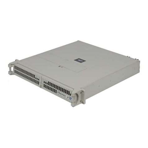
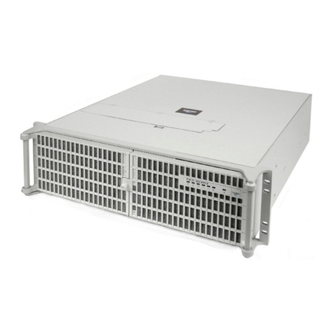
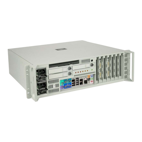
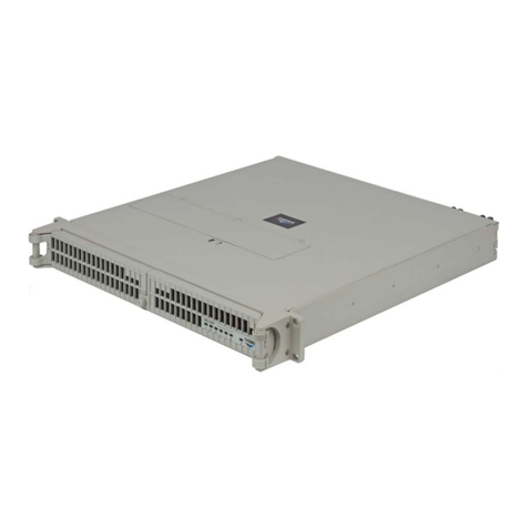
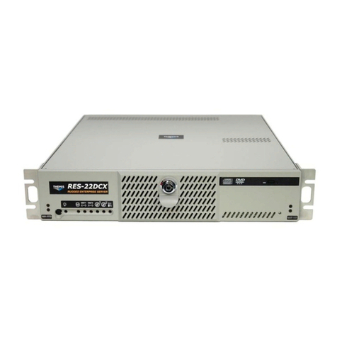
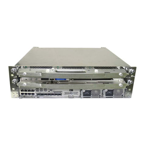
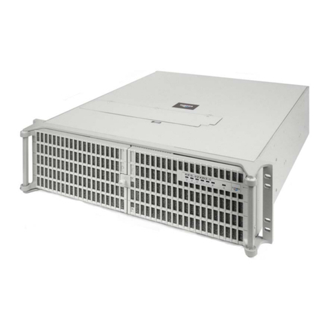
Themis CS-5U User manual

Themis Computer
1
CoolShell CS-5U QuickStart Guide Version 1.0
CS-5U
Package Contents
Sales Demo Configuration 1.4
PN 117219-922
1. One CS-5U chassis, assembled, including:
• 2CPU Blades PN 116899-916
• 1 IO blade PN 117197-922
• 1CMAC
• 3 850W PSUs
• 2 dual disk canisters PN 117198-L01
w/ 3ea. 117343-L01 1TB disks
• 3 power cords
• 2 SFP+ Optical Modules
2. This printed guide
• Note: SAVE the packing materials for
reuse when returning system.
System Notes
I/O and Processor Blade Configurations
Each Processor Blade has two E5540 processors and
24GB of memory (3x4GB for each processor). PCI-e
path with NVIDIA® TeslaTM 20-series wired “up” to
attach to Processor Blade 2. SATA paths resourced so
each processor blade has access to one disk canister.
Disk Canister B1 is allocated to Processor Blade 1.
Disk canister B2 is allocated to Processor Blade 2.
IMPORTANT! Note the position of each compo-
nent in the Slot Diagram. The position of each
component in the chassis is mandatory for this
revision of the chassis management software. (A
future revision will support user configuration of
chassis slot and IO bay assignments). Each com-
ponent will be marked with a unique identifying
number.
Quick Start Guide
Slot 2: I/O Blade 1
Slot 1: Processor Blade 1
CMAC
PSU A PSU B
Slot 4: Empty
Slot 3: Processor Blade 2
Empty
PSU C
I/O Blade Configuration
Bay A Bay B Bay C
Empty Storage Canister (B1) Tesla
Empty Storage Canister (B2)
Slot Diagram

2
Themis Computer
CoolShell CS-5U QuickStart Guide Version 1.0
Blade Removal
• Refer to the illustrations at right.
• Insure that the safety latches are released and in the
up position
• Open both blade latches by pressing both latch but-
tons sideways toward the center of the blade, and
pull the latches out to the open position.
• Pull the blade straight out of the chassis.
• Blade insertion is the reverse of this sequence.
•Removable I/O Blade Handles: The I/O blades
have removable handles, which may be removed for
better access to the I/O blades. If the I/O blade han-
dles are removed, and the I/O blade is to remain in
the chassis, ensure that the safety latches are once
again engaged and the thumb screws inserted and
tightened. This is now the only way to secure the
blade in the chassis, as the blade latches are part of
the blade handle.
CMAC Removal
• Remove the lower panel cover, (if Installed), cover-
ing the lower rack of the CS-5U Chassis by
unscrewing the four (4) captive thumb screws hold-
ing it on.
• Pull the CMAC latch lever out to the open position.
• Pull the CMAC straight out of the chassis.
• To re-install, insure that the latch lever is in the
open position.
• Carefully align the CMAC with the slot position in
the chassis, and push the blade into the slot. As the
latch engages the pawl in the chassis mount, the
handle will start to close. Press the latch into the
closed position until the latch handle clicks into the
groove provided. The latch will not seat until the
CMAC is fully seated.
Power Supply Removal
• To remove, press the release latch to release, and
pull straight out. To install the PSU, carefully align
the power supply unit with its respective slot, and
push in until the release latches click into place.
10Gb BaseT Ethernet Port
SFP+ 10Mb Ethernet
Optical 10Gb Ethernet
Management Terminal
Serial Port
(shown w/SFP+ transceivers installed) Management Port LED Indicators
CMAC Front Panel Detail
Reconfiguration Switch (behind grill)
(currently not supported)
Blade Latches open
Safety Latches up
Blade Latch closed
Safety latch closed
Latch lever open Latch lever closed

Themis Computer
3
CoolShell CS-5U QuickStart Guide Version 1.0
Initial Setup and Operation
Management of the CS-5U is accomplished by connect-
ing a web browser to an HTTP server on the CMAC.
One must configure the CMAC to operate on the host
network, which will require two log-ins, once to set the
network parameters in the CMAC, and again to log the
CMAC in to the host network. The following steps will
accomplish this process. From the point where power is
applied to the PSUs until the CMAC is ready to accept
input could take as long as 4 to 5 minutes. A steady
green LED on the CMAC (CM) indicates it is ready to
accept input.
1. Obtain the network parameters to be assigned to
the CMAC:
• IP Address
• Netmask
• Broadcast Address
•Gateway Address
2. Locate the CS-5U chassis in a convenient loca-
tion for operation.
3. Connect a laptop, with a FireFox or Safari
browser, set to obtain an IP address through
DHCP, to the 10/100Mb Ethernet Management
Port on the CMAC unit with Category 5 (or bet-
ter) cable.
4. Connect power cords to each PSU and to power
outlets. Power is now available to the CS-5U
components through the backplane power net-
work. Each unit will be powered up using the
chassis management software in the CMAC in
the next steps.
5. Bring up a FireFox or Safari browser on the lap-
top. This revision of the GUI does not support
MSIE, thus a Firefox or Safari browser is used.
6. Enter the following CMAC IP address into the
browser address space:
• https://192.168.2.2
7. Look for the LogIn screen to appear (top right).
8. Use ADMIN (all caps) for both User Name and
Password, and click the LogIn button.
9. The Management Control Panel screen will ap-
pear.
10. Select the System Configuration Tab, Network
bar, to configure network parameters.
11. Enter the network parameters obtained in Step 1
into the spaces provided and click Apply.
12. To log out of the Management Control Panel,
click the X in the top right corner. A Cancel/Con-
firm screen will appear. Click Confirm to com-
plete the log out. The successful logout screen
will appear.
13. Disconnect the laptop, and connect the host net-
work to the 10/100Mb Ethernet Management
Port on the CMAC.
14. Operation of the CS-5U management system is
accomplished through the same browser based
interface. Using a Firefox or Safari browser, en-
ter the IP address which was previously assigned
in Step 11 into the address space of the browser,
for instance:
• https://172.30.4.11 (should be the same as
assigned in step 11)
15. When the login screen appears, enter ADMIN
(all caps) for both User Name and Password, and
click the LogIn button. The Management Con-
trol Panel screen will again appear.
16. Select the Remote Control tab, and the System
Power portion of the Remote Control screen will
appear. (next page).
17. Click Press To Turn On.
18. Using the sub-menu power buttons, the CS-5U
may be powered on as a whole unit, or each pro-
cessor blade may be powered on separately. The
Themis System Management
Password:
User Name:
x
LogIn
ADMIN
Management Control Panel
System
Configuration
S
y
ste
m
M
onitorin
g
S
y
ste
m
I
nformatio
n
U
ser
Mana
g
emen
t
R
e
m
o
t
e
Control
M
a
int
e
n
a
n
ce
System Management Access
Alert Management
Clock Settings
Network
x
System Log
System Name foobar
Mac address 00:80:b6:00:44:44
Applying changes to these parameters will disrupt your connection
to the server. You will need to instantiate a new session.
Dynamic
Static
Ip Address:
Netmask:
Broadcast:
Apply
172.30.4.11
172.30.255.255
255.255.0.0
Gateway:
172.30.0.1
10G Switch
4
Themis Computer
CoolShell CS-5U QuickStart Guide Version 1.0
CS-5U may be shut down as a whole, or each pro-
cessor blade may be shut down individually, along
with its associated I/O blade, or each I/O blade may
be shut down individually.
19. When a blade is powered and ready to operate, a
steady green light will show on its front panel.
20. Various equipment parameters may be observed by
clicking the System Monitoring tab. Checking the
checkbox on any component will bring up a graph
of operating parameters which is updated periodi-
cally. These graphs will refresh automatically if
Auto Refresh is on, or they may be refreshed at will
by the Refresh Now button on the Auto Refresh
Control screen.
21. In the event a firmware upgrade is necessary, the
Maintenance tab holds a firmware upgrade screen,
which will allow a firmware upgrade file to be load-
ed for upgrading.
22. The system provides remote access to the processor
blade consoles. To remotely access the console of a
processor blade, select the Remote Control Tab, fol-
lowed by the Console Access bar. Select the Oper-
ating System which is running on the displaying
computer, expand the system list, and click Launch
Console Window for the Processor Blade you wish
to access.
23. To log out of the Management Control Panel, click
the X in the top right corner. A Cancel/Confirm
screen will appear. Click confirm to complete the
log out. The successful logout screen will appear
Management Control Panel
Sy
ste
m
M
on
i
tor
i
n
g
S
y
ste
m
Confi
g
uratio
n
Syste
m
Inf
o
rm
a
ti
o
n
User
M
ana
g
ement
Maintenanc
e
Remote
Control
System Power
Console Access
Fan Speed Control
x
CS5U
Press to turn on
Management Control Panel
System
Monitoring
Sy
ste
m
I
n
fo
rm
a
ti
o
n
S
y
ste
m
Confi
g
uratio
n
U
ser
Mana
g
emen
t
R
e
m
o
t
e
Control
M
a
int
e
n
a
n
ce
Sensor Readings
Auto Refresh Control
Event Logs
x
CS5U
Cmac 0
CpuC - carrier 2
CpuC 4
Fan 1
Fan 2
Temp 1
Temp 2
Temp 3
Temp 4
12189 rpm
11663 rpm
50.75 Degrees C
38.75 Degrees C
50.75 Degrees C
-64.0 Degrees C
CS5U/CpuC 2/CpuC - carrier
2/Fan2
x
11690
11680
11670
11660
11650
11640
11630
010 20 30 40
CS5U/CpuC 2/CpuC - carrier
2/Fan1
x
12220
12210
12200
12190
12180
12170
12160
010 20 30 40
Management Control Panel
System
Monitoring
Sy
ste
m
I
n
fo
rm
a
ti
o
n
S
y
ste
m
Confi
g
uratio
n
U
se
r
Mana
g
emen
t
R
e
m
o
t
e
Control
M
a
int
e
n
a
n
ce
Sensor Readings
Auto Refresh Control
Event Logs
x
Auto Refresh
On
refresh now!
Off
Management Control Panel
S
y
ste
m
M
onitorin
g
S
y
ste
m
Confi
g
uratio
n
S
y
ste
m
Inf
o
rm
a
ti
on
U
ser
M
ana
g
ement
Maintenance
Firmware Upgrade
x
R
emote
C
ontrol
Firmware file:
Browse submit
Management Control Panel
Sy
ste
m
M
onitorin
g
Sy
ste
m
Confi
g
uratio
n
Sy
ste
m
Informatio
n
U
ser
M
ana
g
ement
Mai
nt
e
n
a
n
ce
Remote
Control
System Power
Console Access
Fan Speed Control
x
CS5U
CpuC 2
CpuC 4
Launch Console Window
Please indicate the type of operating system running on the
computer displaying this browser:
Windows (uses absolute mouse coordinates)
Mac/Linux (uses relative mouse coordinates)
n on
n on
x
Cancel Confirm
Are you sure you want to log out?
x
You have successfully
logged out
OK
Themis Computer
47200 Bayside Parkway
Fremont, CA 94538
510-252-0870
http://www.themis.com
Table of contents
Other Themis Server manuals

Themis
Themis RES-32XR3-S User manual

Themis
Themis RES-12XR3-S User manual

Themis
Themis RES-11XR3 User manual

Themis
Themis RES-22XR3 User manual

Themis
Themis RES-22DCX User manual

Themis
Themis CoolShell CS-3U User manual

Themis
Themis RES-22XR3 User manual

Themis
Themis RES-XR4-3U User manual

Themis
Themis RES-32XEL User manual

Themis
Themis RES-22XR3 User manual

Themis
Themis RES-32XR3/FIO User manual

Themis
Themis RES-12DCX User manual

Themis
Themis RES - 32XR3 User manual

Themis
Themis RES-32DCX User manual

Themis
Themis RES-21XR3 User manual

Themis
Themis RES-32XR3-S User manual

Themis
Themis RES-12XR3 User manual

Themis
Themis CoolShell 3U User manual

Themis
Themis 200 User manual

Themis
Themis RES-XR4-1U User manual