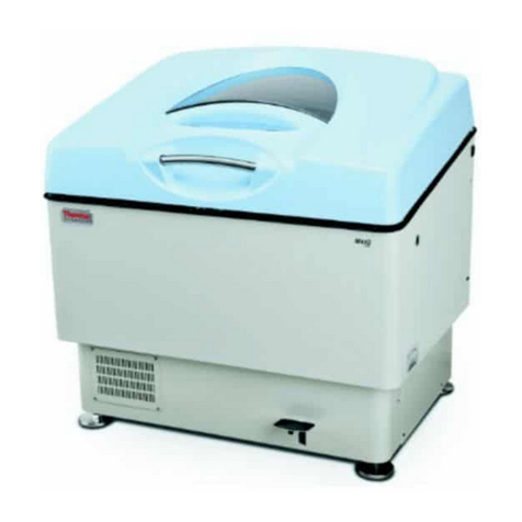
Thermo Scientific 3589 User manual

Multi-Wrist Shaker
Model No.
3589
3589-1CE
057-621-00 • 3/13/08

Safety Information ........................................................................................................................................................3
Alert Signals ..........................................................................................................................................................3
Warnings................................................................................................................................................................3
Description....................................................................................................................................................................5
Specifications ..............................................................................................................................................................6
Electrical Requirements ........................................................................................................................................6
Shaking Speed ......................................................................................................................................................6
Maximum Load ......................................................................................................................................................6
Dimensions ............................................................................................................................................................6
Shipping Weight ....................................................................................................................................................6
Declaration of Conformity ......................................................................................................................................7
Unitʼs Environmental Operating Conditions ..........................................................................................................7
Unpacking and Installation ..........................................................................................................................................8
Shipping Carton ....................................................................................................................................................8
Installing Side Arms ..............................................................................................................................................8
Tri-Grip Clamps ....................................................................................................................................................9
Installing the Optional Utility Tray ..........................................................................................................................9
Electrical Connection ..........................................................................................................................................10
Operation ....................................................................................................................................................................11
Step-by-Step Procedure ......................................................................................................................................11
In Case of Electrical Overload ............................................................................................................................12
Maintenance ..............................................................................................................................................................13
Checking Shaker Attachments ............................................................................................................................13
Inspecting Motor Brushes....................................................................................................................................13
Replacement Parts ....................................................................................................................................................14
Ordering Procedures ..................................................................................................................................................15
Two Year Limited Warranty ........................................................................................................................................16
Table of Contents

Your Thermo Scientific Lab-Line Multi-Wrist Shaker has
been designed with function, reliability and safety in mind.
It is your responsibility to install it in conformance with
local electrical codes. For safe operation, please pay at-
tention to the alert signals throughout the manual.
Warnings
1. Read operation manual before using equipment
to become familiar with the controls and acces-
sories.
2. When operating this equipment, always wear
protective clothing, glasses and other acces-
sories as specified by the safety regulations of
your organization.
3. We recommend that you do not leave equip-
ment unattended while it is in operation. Do not
operate equipment with a damaged electrical
cord or allow cord to come into contact with a
hot surface. Do not operate equipment in an
explosive atmosphere. Do not insert fingers or
other appendages into equipment when it is
operating.
4. Do not modify construction and/or assembly of
equipment. Keep guards in place. Do not
remove tags, labels, decals or other information
from the unit.
5. Make sure all vessels are securely clamped
before turning on unit. Do not operate the unit
at speeds that will cause the contents of vessels
to be thrown out. Wherever possible, vessels
should be stoppered to prevent hazardous sub-
stances being thrown out during the mixing
action. Use extra caution with hot or volatile
substances so that pressure buildup in contain-
er(s) does not cause the stopper to blow off. Do
not run equipment with an unbalanced load. Do
not exceed recommended load.
6. If shaking action will result in the expulsion of
gases or fumes, carry out the operation under a
well-ventilated laboratory hood.
Safety Information
Warning
Warnings alert you to a possibility of
personal injury.
Caution
Cautions alert you to a possibility of
damage to the equipment.
Note
Notes alert you to pertinent facts and
conditions.
Hot Surface
ot surfaces alert you to a possibility of
personal injury if you come in contact
with a surface during use or for a period
of time after use.
Alert Signals
3

7. To eliminate hazard of electrical shock, make
sure floor around machine is dry in the event of
accidental spilling or splashing of liquids, clean
up and/or neutralize the spilled liquids before
continuing.
8. Do not use equipment for other than its intended
purpose. Use only the accessories and attach-
ments that are shipped with the equipment or
are specified for it. Other accessories can pro-
duce hazards or make the unit inoperative.
9. Do not operate shaker for extended periods
under high humidity conditions. Do not operate
shaker in ambient temperatures exceeding
40ºC. Do not operate shaker in a CO2 enriched
atmosphere.
10. Perform regular maintenance service as speci-
fied in this manual and keep unit in good repair.
Do not operate with known defects. Always dis-
connect equipment from power source before
servicing or performing any maintenance proce-
dures.
4
SAFETY INFORMATION

The Lab-Line Model 3589 Multi-Wrist Shaker is a general-
purpose laboratory shaker designed to simulate hand
mixing. Its action can be varied from a gentle swishing
motion to vigorous agitation. The shaking arms (ordered
separately) rotate through an arc of less than 2 degrees
to produce a great deal of torque using very little power.
A built-in shaker timer can be set for continuous shaking
or a timed cycle up to one hour in length. The cast-iron
body and well-balanced mechanism prevent creeping
under all but the most extreme conditions.
Accessories for the Multi-Wrist Shaker include a utility
tray to hold odd shaped containers. Refer to the upcom-
ing REPLACEMENT PARTS LIST for a list of available
attachments.
5
Description

6
Electrical Requirements
3589: 120 Volts, 60 z, 65 Watts, 0.5 Amps
3589-1CE: 220/240 Volts, 50/60 z, 30 Watts, 0.4 Amps
Shaking Speed
30-750 rpm (speed range is dependent on weight of
glassware and contents)
Maximum Load
10 lbs. (4.5 kg)
Dimensions
Body Only (without arms):
11”W x 15”D x 10” (28cm x 38cm x 25cm)
4-position side arms, #3587-4:
9-3/4” (24cm) long, each (2)
8-position side arms, #3587-8:
19-3/4” (50cm) long, each (2)
Shipping Weight
65 lbs. (29 kg) - body only, without arms
Specifications

Declaration of Conformity
(for CE models only)
We hereby declare under our sole responsibility that this product conforms with the technical requirements of
the following standards:
EMC: EN 61000-3-2 Limits for harmonic current emissions
EN 61000-3-3 Limits for voltage fluctuations and flicker
EN 61326-1 Electrical equipment for measurement, control, and
laboratory use; Part I: General Requirements
Safety: EN 61010-1 Safety requirements for electrical equipment for
measurement, control, and laboratory use;
Part I: General Requirements
EN 61010-2-051 Part II: Particular requirements for laboratory equipment for
mixing and stirring
per the provisions of the Electromagnetic Compatibility Directive 89/336/EEC, as amended by 92/31/EEC and
93/68/EEC, and per the provisions of the Low Voltage Directive 73/23/EEC, as amended by 93/68/EEC.
The authorized representative located within the European Community is:
Thermo Fisher Scientific
419 Sutton Road
Southend On Sea
Essex SS2 5P
United Kingdom
Copies of the Declaration of Conformity are available upon request.
Unitʼs Environmental Operating Conditions
Pollution Degree: 2
Installation Category: II
Altitude: 2000 meters MSL (Mean Sea Level)
umidity: 80% maximum, non-condensing
Electrical Supply: 120VAC or 240VAC
Voltage Tolerance: ±10% of normal rated line
Temperature: 15°C to 40°C
Product Usage: This product is intended for use indoors on y
7
SPECIFICATIONS

8
Shipping Carton
The shipping carton should be inspected upon delivery.
When received, carefully examine for any shipping dam-
age before unpacking. If damage is discovered, the deliv-
ering carrier should both specify and sign for the damage
on your copy of the delivery receipt.
Open the carton carefully making certain that all parts are
accounted for before packaging materials are discarded.
After unpacking, if damage is found promptly report it to
the carrier and request a damage inspection promptly.
IMPORTANT: Failure to request an inspection of damage
within a few days after receipt of shipment absolves the
carrier from any liability for damage. You must call for a
damage inspection promptly.
Installing Side Arms
1. Prepare the side arm by inserting a setscrew
into each of the holes in the bottom of each side
arm. Use the Allen wrench supplied with the
accessories. The top of each arm has 2 holes
for mounting other accessories.
2. Mount each side arm on the shaker's shaft with
the setscrews on the bottom of each arm point-
ing toward the flat part of the shaft. When the
screws are snug, twist each arm back and forth
slightly while tightening the setscrews to insure
that the arm is properly aligned. Tighten the
setscrews securely.
SUGGESTION: Insert the long end of the Allen wrench
into the setscrew and turn until it is in place. Then, insert
the short end into the screw and tighten securely.
Unpacking and Installation

9
Tri-Grip Clamps
The side arms are shipped with the tri-grip clamps already
mounted. In the event that the clamps need to be removed,
note that they are mounted to the side arms by a single
setscrew on the bottom of the side arm and that a
sequence of assembly is followed.
1. Slide each tri-grip clamp into a hole in a side arm.
The clamp closest to the body should reach back-
ward from the unit the next closest clamp should
reach forward, and so on until all clamps are
installed.
2. Position each clamp so that the rear of its shaft
extends slightly from the side arm and so that the
clamp will hold items at the desired angle. Secure
each clamp to the side arm by tightening the
setscrew on the bottom of the side arm. For those
applications requiring the clamps to be positioned
vertically, rotate the side arms 90º.
Installing the Optional Utility Tray
1. A utility tray is available as an option and can be
used to increase the capacity of the shaker. To
install the utility tray, center the tray over the shak-
er body. Line up the holes on the mounting brack-
ets of the tray with the holes located on the top of
the side arms.
2. Screw in the mounting bolts using a 1/4-inch Allen
wrench. Tighten securely.
3. Check for tightness periodically.
4. Carefully position vessels on the tray. Be careful
not to fill vessels to levels where spilling might
occur during shaking action.
UNPACKING AND INSTALLATION

Electrical Connection
Model 3589 requires a 120V, 60 z power source. It is
supplied with a 3-wire line cord. It should be connected
to an outlet designed for 3-prong plugs. If an extension
cord is used, it also should be the 3-wire grounded type.
For an outlet designed to accept 2-prong plugs
(ungrounded), it is required that a qualified electrician
replace the outlet with a new grounded type.
Model 3589-1CE requires 220-240V~, 50/60 z power
source. Because of the variety of plug configurations in
use worldwide for 240 VAC power, the unit is furnished
with the plug removed. The user must install a plug to
conform with local code and configuration requirements.
Leave the unit disconnected when not in use to avoid
accidental turning on of the unit with possibility of injury.
10
UNPACKING AND INSTALLATION

Operation
Warning
Do not use in the presence of flam-
mable or combustible materials or
explosive gases. Do not use in the
presence of pressurized or sealed
containers—fire or explosion may
result, causing death or severe
injury.
Note
Depress metal tab prior to rotating
knob—the tab fixes knob setting and
prevents inadvertent motion of the
knob.
Metal Ta b
1
3
2
4
1. POWER-ON STATUS LAMP: Lit when the unit
power is on.
2. SPEED CONTROL: Sets shaking speed.
3. CIRCUIT BREAKER: Push in to re-set unit in the
event of an overload.
4. TIMER: Set time of an operation up to 1 hour.
Step-by-Step Procedure
1. Connect cordset to proper electrical outlet as
described in the previous INSTALLATION section.
2. Check the side arms, clamps and accessories to
make sure that they are securely tightened.
3. Load the unit with the items to be shaken.
4. Start with timer knob in 0 or off position and speed
control in off position.
11

12
OPERATION
5. Set the timer for the desired time period (up to one
hour) or turn counterclockwise to CONSTANT posi-
tion for continuous shaking.
6. In order to overcome initial inertia of the load, turn
the speed control to point where shaking just starts.
7. Gradually increase shaking speed to the desired
level being careful to observe that containers and
contents remain secure. If any danger is inherent in
work being carried out, proper shielding should be in
place or work should be conducted in well-ventilated
laboratory hood.
In Case of Electrical Overload
The unit is protected against electrical overload by pushbut-
ton, re-settable circuit breaker(s). If an overload occurs, the
breaker(s) will trip.
To re-set the circuit breaker(s), unplug the unit and push the
button in. owever, if the breaker(s) trip repeatedly, unplug
the unit and have the shaker serviced.
Note
Depending on load, this may be
between 2 to 3 on the speed control
scale.

13
A Multi-Wrist Shaker requires regular inspection for loose
clamps, side arms and accessories. Every 6 months an
examination should be made of the motor brushes for
wear. Because it has sealed ball bearings, the motor
does not require lubrication.
Checking Shaker Attachments
Before each use, be sure to check for loose clamps, side
arms and accessories. Use the Allen wrench supplied
with the accessories to tighten the items securely.
Inspecting Motor Brushes
1. Remove the 2 screws at the lower corners of
the back of the unit and remove the back cover.
2. Unscrew the brush-retaining cap located on the
motor end away from the motor shaft. Note how
brush is oriented before removing. Take hold of
spring to remove.
3. Install new brush when old brush is less than
1/4-inch long. For optimum shaker perform-
ance, replace BOT brushes, even though only
one may be worn below 1/4-inch.
4. On the opposite side, insert a short screwdriver
and manipulate to remove brush-retaining cap.
As before, note orientation of old brush and
remove. Install new brush in the same position,
replace cap and tighten. Replace back cover.
Maintenance
Warning
Disconnect from the power supply
prior to maintenance and servicing.
Warning
Refer servicing to qualified personnel.
Note
PCB contacts at rear of controller fit
into contacts at rear of controller
housing.

14
Replacement Parts
Description Part No.
Circuit Breaker-2-amp, 120V: 330-114-00
Circuit Breaker-0.8-amp, 240V: 330-399-00
Cordset, 120V: CR1473X1
Cordset, 240V: CR1472X1
Strain Relief: Part of cordset
Speed Control, 120V: 227-841-00
Speed Control, 240V: 229-419-00
Knob: 560-223-00
Knob, Locking Tab: 600-125-00
Line Filter: 330-345-00
Motor – 1/17 hp (3589): MT1473X1
Motor – 1/17 hp (3589-1CE): MT1473X2
Status Lamp Base: 360-249-01
Status Lamp Lens, Green: 360-238-00
Setscrew, 1/4-20 x 3/8": 566-301-00
Timer (60 Minute): 270-135-00
Mounting Feet: 790-078-00
Wiring Diagram, 3589: 228-010-00
Wiring Diagram, 3589-1CE: 229-304-00
ACCESSORIES:
3587-4: 4-Place Side Arms, Pair (includes 8 clamps)
3587-8: 8-Place Side Arms, Pair (includes 16 clamps)
3587-10: Alumaloy Tri-Grip Clamps, Pair
3589-5: Utility Tray

15
Ordering Procedures
Please refer to the Specification Plate for the complete
model number, serial number, and series number when
requesting service, replacement parts or in any corre-
spondence concerning this unit.
All parts listed herein may be ordered from the Thermo
Scientific dealer from whom you purchased this unit or
can be obtained promptly from the factory. When service
or replacement parts are needed we ask that you check
first with your dealer. If the dealer cannot handle your
request, then contact our Customer Service Department
at 563-556-2241 or 800-553-0039.
Prior to returning any materials, please contact our
Customer Service Department for a “Return Materials
Authorization” number (RMA). Material returned without
an RMA number will be refused.

16
Two Year Limited Warranty
This Thermo Scientific product is warranted to be free of defects in materials and workmanship for two (2)
years from the first to occur of (i) the date the product is sold by the manufacturer or (ii) the date the product is
purchased by the original retail customer (the “Commencement Date”). Except as expressly stated above, the
MANUFACTURER MAKES NO OT ER WARRANTY, EXPRESSED OR IMPLIED, WIT RESPECT TO T E
PRODUCTS AND EXPRESSLY DISCLAIMS ANY AND ALL WARRANTIES, INCLUDING BUT NOT LIMITED
TO, WARRANTIES OF DESIGN, MERC ANT ABILITY AND FITNESS FOR A PARTICULAR PURPOSE.
An authorized representative of the manufacturer must perform all warranty inspections. In the event of a
defect covered by the warranty, we shall, as our sole obligation and exclusive remedy, provide free replace-
ment parts to remedy the defective product. In addition, for products sold within the continental United States
or Canada, the manufacturer shall provide free labor to repair the products with the replacement parts, but
only for a period of ninety (90) days from the Commencement Date.
The warranty provided hereunder shall be null and void and without further force or effect if there is any (i)
repair made to the product by a party other than the manufacturer or its duly authorized service representa-
tive, (ii) misuse (including use inconsistent with written operating instructions for the product), mishandling,
contamination, overheating, modification or alteration of the product by any customer or third party or (iii) use
of replacement parts that are obtained from a party who is not an authorized dealer of Thermo Scientific prod-
ucts.
eating elements, because of their susceptibility to overheating and contamination, must be returned to the
factory and if, upon inspection, it is concluded that failure is due to factors other than excessive high tempera-
ture or contamination, the manufacturer will provide warranty replacement. As a condition to the return of any
product, or any constituent part thereof, to the factory, it shall be sent prepaid and a prior written authorization
from the manufacturer assigning a Return Materials Number to the product or part shall be obtained.
IN NO EVENT S ALL T E MANUFACTURER BE LIABLE TO ANY PARTY FOR ANY DIRECT, INDIRECT,
SPECIAL, INCIDENTAL, OR CONSEQUENTIAL DAMAGES, OR FOR ANY DAMAGES RESULTING FROM
LOSS OF USE OR PROFITS, ANTICIPATED OR OT ERWISE, ARISING OUT OF OR IN CONNECTION
WIT T E SALE, USE OR PERFORMANCE OF ANY PRODUCTS, W ET ER SUC CLAIM IS BASED ON
CONTRACT, TORT (INCLUDING NEGLIGENCE), ANY T EORY OF STRICT LIABILITY OR REGULATORY
ACTION.
For the name of the authorized Thermo Scientific product dealer nearest you or any additional information, contact us:
2555 Kerper Blvd., Dubuque, Iowa, 52004-0797
Phone: 563-556-2241 or 1-800-553-0039
Fax: 563-589-0516
E-mail: mkt@thermofisher.com
Web: www.thermo.com
This manual suits for next models
1
Table of contents
Other Thermo Scientific Paint Sprayer manuals