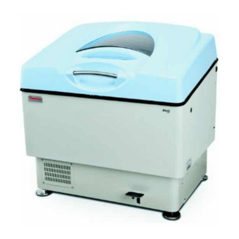
Thermo Scientific MaxQ 2000 CO2 Plus User manual

Visit us online to register your warranty
www.thermoscientific.com/labwarranty
User Manual
MaxQ 2000 CO2 Plus
Digital CO2 Resistant Shaker
Catalog #88881101, #88881102
Operation Manual 0000847

Thermo Scientific
MANUAL NUMBER 0000-847
0 -- 06/ 06 /2017 Original
REV ECR/ECN DATE DESCRIPTION By
Preface
CO2 Resistant Shaker i

Thermo Scientificii CO2 Resistant Shaker
Preface
Do You Need Information or Assistance on
Thermo Scientific Products?
If you do, please contact us 8:00 a.m. to 6:00 p.m. (Eastern Time) at:
1-740-373-4763 Direct
1-800-438-4851 Toll Free, U.S. and Canada
1-877-213-8051 FAX
http://www.thermoscientific.com Internet Worldwide Web Home Page
service.led.marietta@thermofisher.com Tech Support Email Address
Certified Service Web Page
Our staff can provide information on pricing and give you quotations. We can
take your order and provide delivery information on major equipment items or make
arrangements to have your local sales representative contact you. Our products are listed on the
Internet and we can be contacted through our Internet home page.
Our staff can supply technical information about proper setup, operation or
troubleshooting of your equipment. We can fill your needs for spare or replacement parts or
provide you with on-site service. We can also provide you with a quotation on our Extended
Warranty for your Thermo Scientific products.
Whatever Thermo Scientific products you need or use, we will be happy to discuss your
applications. If you are experiencing technical problems, working together, we will help you
locate the problem and, chances are, correct it yourself...over the telephone without a service
call.
When more extensive service is necessary, we will assist you with direct factory trained
technicians or a qualified service organization for on-the-spot repair. If your service need is
covered by the warranty, we will arrange for the unit to be repaired at our expense and to your
satisfaction.
Regardless of your needs, our professional telephone technicians are available to assist you
Monday through Friday from 8:00 a.m. to 6:00 p.m. Eastern Time. Please contact us by
telephone or fax.
International customers, please contact your local Thermo Scientific distributor.
Sales Support
Service Support
www.unitylabservices.com

CO2 Resistant Shaker iiiThermo Scientific
Table of Contents
Unpacking and Installation . . . . . . . . . . . . . . . . . . . . . . . . . . . . . . . . . . . .1-1
Universal (Aluminum) Platform Installation . . . . . . . . . . . . . . . . . . .1-3
Rubber Mat Platform Installation . . . . . . . . . . . . . . . . . . . . . . . . . . .1-4
Connections of the Instrument . . . . . . . . . . . . . . . . . . . . . . . . . . . . .1-5
Overview . . . . . . . . . . . . . . . . . . . . . . . . . . . . . . . . . . . . . . . . . . . . . . . . . . . .2-1
Specifications . . . . . . . . . . . . . . . . . . . . . . . . . . . . . . . . . . . . . . . . . . .2-1
Safety Tips . . . . . . . . . . . . . . . . . . . . . . . . . . . . . . . . . . . . . . . . . . . . .2-2
Storing the Signal Cable . . . . . . . . . . . . . . . . . . . . . . . . . . . . . . . . . . .2-2
Maximum Shaking Speed . . . . . . . . . . . . . . . . . . . . . . . . . . . . . . . . .2-3
Operation . . . . . . . . . . . . . . . . . . . . . . . . . . . . . . . . . . . . . . . . . . . . . . . . . . . .3-1
Operations on the Control Panel . . . . . . . . . . . . . . . . . . . . . . . . . . . .3-1
Speed and Time Settings . . . . . . . . . . . . . . . . . . . . . . . . . . . . . . . . . .3-2
Alarm System . . . . . . . . . . . . . . . . . . . . . . . . . . . . . . . . . . . . . . . . . . .3-3
Application . . . . . . . . . . . . . . . . . . . . . . . . . . . . . . . . . . . . . . . . . . . . . . . . . .4-1
Safety Tips and Maintenance . . . . . . . . . . . . . . . . . . . . . . . . . . . . . . . . . .5-1
Optional Accessories . . . . . . . . . . . . . . . . . . . . . . . . . . . . . . . . . . . . . . . . .6-1
Troubleshooting . . . . . . . . . . . . . . . . . . . . . . . . . . . . . . . . . . . . . . . . . . . . . .7-1
Warranty Information . . . . . . . . . . . . . . . . . . . . . . . . . . . . . . . . . . . . . . . . .8-1
Section 1
Section 2
Section 3
Section 4
Section 5
Section 6
Section 8
Section 7


CO2 Resistant Shaker 1-1Thermo Scientific
Section 1 Unpacking and Installation
1. Inspect contents upon receipt of the instrument, if the instrument is
upside down, contact the manufacturer immediately.
2. Check packing list below. If there are any damaged or missing items,
contact the manufacturer.
3. Place the instrument on a level and firm surface, to avoid vibration and
noise.
Thermo Scientific
Cat. No. 88881101 88881102 88881103 88881104
Picture
Model name on
carton box label
MaxQ2000CO2
Plus, 100-240V,
for USA
MaxQ2000CO2
Plus, 100-240V,
various plugs
MaxQ2000CO2 Plus
Promotion Package
for USA, includes
CO2 resistant shaker
(88881101), Universal
Platform and Flask
Clamp Starter Kit
MaxQ2000CO2 Plus
Promotion Package for
EMEA & APAC, includes
CO2 resistant shaker
(88881102), Universal
Platform & Flask Clamp
Starter Kit
Main Body 1 1 1 1
Control Box 1 1 1 1
General Power
Adaptor 1 1 1 1
US Plug 1 N/A 1 N/A
CN Plug N/A 1 N/A 1
EU Plug N/A 1 N/A 1
Table 1-1. Packing List

1-2 CO2 Resistant Shaker Thermo Scientific
Section 1
Unpacking and Installation
Table 1-1. Packing List (continued)
Thermo
Scientific
Cat. No.
88881101 88881102 88881103 88881104
Picture
Model name
on carton box
label
MaxQ2000CO2
Plus, 100-240V,
for USA
MaxQ2000CO2
Plus, 100-240V,
various plugs
MaxQ2000CO2 Plus
Promotion Package
for USA, includes CO2
resistant shaker
(88881101), Universal
Platform and Flask
Clamp Starter Kit
MaxQ2000CO2 Plus
Promotion Package for
EMEA & APAC, includes
CO2 resistant shaker
(88881102), Universal
Platform & Flask Clamp
Starter Kit
UK Plug N/A 1 N/A 1
Universal
Platform (AL) N/A N/A 1 1
100ml Flask
Clamp N/A N/A 2 2
250ml Flask
Clamps N/A N/A 4 4
500ml Flask
Clamps N/A N/A 4 4
1L Flask Clamps N/A N/A 2 2
2L Flask Clamps N/A N/A 2 2

CO2 Resistant Shaker 1-3Thermo Scientific
Section 1
Unpacking and Installation
1. Place the instrument on a level and firm surface; it must be capable
of supporting the weight and load of the instrument, and the impact
force generated by the motion. Prepare related parts (see Figure 1-1).
1) M4x10 cross recessed countersink head screws
2) Universal (aluminum) platform
3) Main body of CO2 resistant shaker
2. Install the horizontal universal platform on the fixed plate of the Main
body, ensure all four mounting holes in the universal platform and the
four threaded mounting holes are in alignment
3. Fasten the universal platform and the fixed plate with four M4x10
cross recessed countersink head screws.
Universal (Aluminum)
Platform Installation
Figure 1-1. Universal Platform Installation Diagram

1. Place the instrument on a level and firm surface; it must be capable
of supporting the weight and load of the instrument and the impact
force generated by the motion. Prepare related parts (see Figure 1-2).
1) Rubber mat
2) M4x10 cross recessed countersunk head screws
3) Platform
4) Main body of CO2 resistant shaker
2. Install the horizontal platform on the fixed plate of the Main body;
ensure all four mounting holes on the platform and the four threaded
mounting holes are in alignment.
3. Fasten the platform and the fixed plate with four M4x10 cross recessed
countersink head screws.
4. Place the rubber mat on the platform.
1-4 CO2 Resistant Shaker Thermo Scientific
Section 1
Unpacking and Installation
Rubber Mat Platform
Installation
Figure 1-2. Rubber Mat Platform Installation Diagram

Refer to Figure 1-3 when connecting the instrument.
1) Main body of CO2 resistant shaker
2) Control box
3) Power adapter
4) Power cord
CO2 Resistant Shaker 1-5Thermo Scientific
Section 1
Unpacking and Installation
Connections of the
Instrument
Figure 1-3. Circuit Diagram


CO2 Resistant Shaker 2-1Thermo Scientific
Section 2 Overview
Speed
Speed Range . . . . . . . . . . . . . . . . . . . .30-300 RPM
Speed Accuracy . . . . . . . . . . . . . . . . . . . . .±1 RPM
Motion Type . . . . . . . . . . . . . . . . . . . . . . . .Orbital
Orbit Diameter . . . . . . . . . . . . . . . . . . . . .Ø19mm
Display . . . . . . . . . . . . . . . . . . . . . . . . . . . . . .LED
Display Accuracy . . . . . . . . . . . . . . . . . . . . .1 RPM
Maximum Load . . . . . . . . . . . . . . . . . . . . . . . .6 kg
Timer
Timer Range . . . . . . . . . . . . . . . . .0~99h 59min.
Hour Display . . . . . . . . . . . . . . . . . . . . . . . . .LED
Minute Display . . . . . . . . . . . . . . . . . . . . . . . .LED
Dimensions (WxDxH)
Main body . . . . .360 x 300 x 96mm (14.2 x 11.8 x 3.8 inch)
Control Box . . . . 95 x 158 x 26mm (3.7 x 6.2 x 1.0 inch)
Weight
Main body
Net Weight . . . . . . . . . . . . . . . .17.5 kg (38.58 lbs)
Control Box
Net Weight . . . . . . . . . . . . . . . .0.3 kg (0.66 lbs)
Gross weight . . . . . . . . . . . . . . . .19 kg (41.9 lbs)
Ambient
Altitude . . . . . . . . . . . . . . . . . . . . . . . . . .<2,000 m
Temperature . . . . . . . . . . . . . . . . . . . .4°C to 60°C
Relative Humidity . . . . . . . . . . . . . . .20% to 99%
CO2Concentration . . . . . . . . . . . . . . .0% to 20%
Storage Conditions
Altitude . . . . . . . . . . . . . . . . . . . . . . . . . .<2,000m
Temperature . . . . . . . . . . . . . . . . . . . .5°C to 60°C
Relative Humidity . . . . . . . . . . . . . . .20% to 90%
Other
Noise level . . . . . . . . . . . . . . . . . . . . . . . . . .<60dB
Certification . . . . .ROHS, WEEE, CSA, CE Mark
Power supply . . . . . . . .100-240VAC, 50Hz/60Hz
Specifications
Certification . . . . .RoHS, WEEE, cCSAus, CE Mark

2-2 CO2 Resistant Shaker Thermo Scientific
Section 2
Overview
Safety Tips
Storing the Signal
Cable
1. Unplug and unload before moving the unit.
2. This instrument uses a single-phase AC100-240V 50/60Hz power
supply.
3. Remove the power supply when the instrument is in maintenance.
4. DO NOT clean the unit with flammable or corrosive liquid.
5. Use specified power supply.
6. Maximum load 6kg, 13.23 lbs.
7. To ensure proper operation, the unit must be free of surrounding
obstructions.
To store the signal cable, simply open the side plate on the main body.
Refer to Figure 2-1. The signal cable can be placed inside.
Caution When storing the cable, pay attention to closing the side plate
door, to avoid pinching your fingers. ▲
1) Main body of CO2 resistant shaker
2) Side plate
3) Control box
Figure 2-1. Storing the Signal Cable Diagram

CO2 Resistant Shaker 2-3Thermo Scientific
Section 2
Overview
Maximum Shaking
Speed
Table 2-1. Maximum Shaking Speed on Rubber Platform in Relation to Flask Size
Table 2-2. Maximum Shaking Speed and Flask Capacity on Universal Platform
Note The flask clamps (<2L) can be placed anywhere on the universal
(aluminum) platform, even if the load is not balanced. ▲
Running speed
Flask Size 0-150rpm 0-200rpm
50ml √
100ml √
150ml √
200ml √
250ml √
500ml √
1000ml √ —
2000ml √ —
3000ml √ —
5000ml √ —
Flask clamp Maximum Flask
Capacity
Running speed(rpm)
Size Liquid volume 0-200 0-300
50ml ≤50ml 30 √
100ml ≤100ml 15 √
150ml ≤150ml 15 √
200ml ≤200ml 15 √
250ml ≤250ml 15 √
500ml ≤500ml 9 √
1000ml ≤500ml 6 √
≤1000ml 6 √ —
2000ml ≤1000ml 4 √
≤2000ml 2 √ —
3000ml ≤1500ml 2 √
≤3000ml 2 √ —
5000ml ≤2500ml 1
≤5000ml 1 √ —
√ —


CO2 Resistant Shaker 3-1Thermo Scientific
Section 3 Operation
The unit has been designed with a “soft start/slowdown” providing a
smooth acceleration/deceleration during operation. This feature will
decrease splashing of solutions from vessels during operation.
Warning The microprocessor control system may take 1 minute to
synchronize the actual RPM of the universal (aluminum) platform to the
desired RPM setting. Make sure that all the flasks and test tubes are firmly
fixed on the universal platform and the flask clamps are fasten securely
with the screws. ▲
4 digit LEDs, 4 indicator lights and 5 buttons.
Operations on the
Control Panel
1) Display LED: Shows time or speed
2) RPM indicator light: LED shows current speed
3) TIME indicator light: LED shows current time.
4) WARN indicator light: Over-speed alarm.
5) RUN indicator light: The instrument is running.
6) RPM/TIME Key: While instrument is in operation,
press to change time and speed display; when setting
parameter, press to change minutes, hour or speed.
7) Up Arrow Key: Increases value. Hold for 3 seconds to
increase rapidly.
8) Down Arrow Key: Decreases value. Hold for 3 seconds
to decrease rapidly.
9) Key: The power is On/Off.
10) Key: The instrument is running or stopped.

3-2 CO2 Resistant Shaker Thermo Scientific
Section 3
Operation
Speed and Time Settings Speed setting
1. Press RPM/TIME key. The speed indicator light is lit.
2. Press up and down arrow keys to access the speed setting state, speed
value starts flashing.
3. Press up and down arrow keys to change the speed value. Speed
increases or decreases. The minimum unit is 1rpm.
4. During settings, the unit will reset to current values if no value is input
after three seconds.
5. Press key to run or stop.
Time setting
1. Press RPM/TIME key. The time indicator light is lit.
2. Press up and down arrow keys to access the time setting state. Speed
value starts flashing;
3. Press up and down arrow keys to change the time value. Time increases
or decreases. The minimum unit is 1 minute or 1 hour.
4. During settings, the unit will reset to current values if no value is input
after three seconds.
5. Press key to run or stop.
Notes
1. When the shaker is running, the LED display will switch between the
speed and timer function every 30 seconds automatically. Press
RPM/TIME key to manually toggle between the speed and timer
value.
2. In “timer mode” the LED display will show the remaining running
time.
3. In “continuous mode” the LED display will show elapsed run time.
4. After the run is complete, the LED display will read “end”. Press any
key to place the shaker in standby mode.

CO2 Resistant Shaker 3-3Thermo Scientific
Section 3
Operation
Alarm System
1. During operation, the alarm will sound after 10 seconds if the unit has
not begun shaking. In addition, the alarm will sound and stop for the
speed over 350 rpm after 2 seconds.
2. Once the shaker begins to alarm, the RUN indicator light will not be
visible and the WARN indicator light will flash, and the unit will stop
running.
Power failure recovery
When the power supply is cut off suddenly to the shaker, resulting in a
power failure, the unit will automatically run at the previous set parameter
upon power restoration.
Alarm System


CO2 Resistant Shaker 4-1Thermo Scientific
Section 4 Application
Application on Lab Benches
To operate the shaker outside of a CO2 incubator, refer to Specifications
in Section 2.
Application in CO2 Incubator
Place the main body of the shaker in the CO2 incubator, and use the
signal cable to connect the control box through the access port of the CO2
incubator. Refer to Figure 4-1.
1) CO2 Incubator
2) Control Box
3) Power Cord
4) Main body of CO2 Resistant Shaker
Figure 4-1. Application in CO2 incubator
Other manuals for MaxQ 2000 CO2 Plus
2
This manual suits for next models
2
Table of contents
Other Thermo Scientific Paint Sprayer manuals