manuals.online logo
Brands
  1. Home
  2. •
  3. Brands
  4. •
  5. Thetford
  6. •
  7. Plumbing Product
  8. •
  9. Thetford Aqua-Magic 33186 User manual

Thetford Aqua-Magic 33186 User manual

fromLowerMechanism
either by pushing Rod
Link to the right with a
screwdriver (Fig. 4) or
by using your finger to
pulltheRodLinktotheright.
6. Use Hog-Ring Pliers to
disconnect Hog Ring
and hose from Valve.
7. Remove Lower Mecha-
nism from base.
New Part Installation
1. Pull up on Link Rod to
open Blade.
2. Position Lower Mecha-
nismoverbottomoftoi-
let. Use Hog Ring Pliers
toconnectHogRingand
hosetonew
valve.(Fig.2).
3. Center and install Rod
Clip on Lower Mechan-
ism’s Pedal Arm (Figs.
3-4).
4. Align and install Rod
Link to Pedal Arm As-
sembly, securing Rod
Link Clip to Rod Link
(Figs. 3-4).
5. Resecure five Mecha-
nism-to-BaseScrewsin
this order: lower left-
hand corner (1 3/4
inches long), three
around opening (2
inches long) and upper
left-hand corner (1 1/4
inches long) (Fig. 2).
First screw (lower
lefthand corner) needs
Loctite Thread-Locker
and must go through
Lower Mechanism base
and hole in metal con-
necting bracket from
Upper Mechanism.
Toilet Installation
1. InstallnewClosetFlange
in toilet bottom (lip ori-
ented down).
2. Reinstall toilet, revers-
ing “Toilet Removal”
steps above.
3. Flush test. Check for
leaks.
Fig. 3
Fig. 4
Rod
Link
Clip
5. Défairelatigederaccord
du mécanisme inférieur,
soit en poussant la tige
de raccord vers la droite
àl’aided’untournevis(ill.
4) ou en se servant d’un
doigtpour tirer latige de
raccord vers la droite.
6. Utiliser la pince pliante
pour anneaux ouverts
pour défaire l’anneau
ouvert et le tuyau du
robinet.
7. Retirer le mécanisme
inférieur de la base.
Installation de la
nouvelle pièce
1. Tirer sur la tige de rac-
cord pour ouvrir la pale.
2. Positionner le mécan-
ismeinférieurau-dessus
du bas du cabinet.
Utiliserunepincepliante
pour anneaux ouverts
pour raccorder l’anneau
ouvert et le tuyau à la
nouvellesoupape(ill.2).
3. Centrer et installer la
pince de tige sur le bras
de la pédale du mécan-
isme inférieur (ill. 3-4).
4. Aligneret installer la tige
de raccord au bras de la
pédale, en fixant la pince
de la tige de raccord (ill.
3-4).
5. Fixer à nouveau les vis
qui retiennent le mécan-
isme à la base dans
l’ordre suivant : coin
gauche inférieur (long. 1
3/4 po), trois autour de
l’ouverture(long.2po)et
coin gauche supérieur
(long. 1 1/4 po) (ill. 2).
De l’enduit Loctite doit
être utilisé pour la
première vis (coin
gaucheinférieur)quidoit
passer par la base du
mécanismeinférieuretle
trouqui raccorde le sup-
port en métal du méca-
nisme supérieur.
Installation du cabinet
1. Installer un nouveau joint
d’étanchéitédelabridedesolau
fond du cabinet (la lèvre de joint
tournée vers le bas).
2.Réinstallerlecabineteninversant
les étapes du retrait du cabinet
ci-dessus.
3. Tirer la chasse pour effectuer un
test et vérifier s’il y a des fuites.
Made in U.S.A./Fabriqué aux É.-U. Form No./Node formulaire 19300 Rev. 9/24/02
Thetford Corporation • P.O. Box 1285 • Ann Arbor, MI • 48106
pince de
la tige de
raccord
(Removal/
retrait)
Do not substitute
worm drive clamps
for Hog-Ring Clamps.
Tools Needed
•1/2” Wrench
• Channel Locks
•Hog-Ring Pliers
• Phillips-Head
Screwdriver
•Flat-Head Screw-
driver
• Loctite Thread-
Locker
Toilet Removal
1. Turnoffwatersupply
to toilet (see vehicle
Owner’s Manual).
2. At back base of toi-
let,removewaterline
from Water Valve El-
bow while support-
ingElbowwithChan-
nel Locks.
3. RemoveSideAccess
Covers from base of
toilet.
4. Remove nuts hold-
ing toilet to floor.
5. Lift toilet from floor.
6. Remove old Closet
FlangeSealfromtoi-
let or floor.
Old Part Removal
1. Turn toilet upside
down.
3. Remove 5 Mecha-
nism-to-Base
PhillipsHeadScrews
(Fig. 2).
4. Use Flat-Head
Screwdriver to dis-
connect (pop) Rod
Link Clip from Rod
Link (Figs. 2 & 3).
5. DisconnectRodLink
Aqua-Magic®Aurora®Lower Mechanism Replacement Assembly
Fig. 2 – Bottom ofToilet / Bas du cabinet
Mechanism-to-
Base Screws
Vis qui
retiennent le
mécanisme à la
base
Pedal Arm (Rod
Link Clip below
here)
Bras de pédale
(pince de la
tige de raccord
en-dessous)
A. Anneau(x) ouvert(s)
B. Robinet casse-vide
C. Tuyau de la chasse
D. Mécanisme supérieur
E. Buse de chasse
F. Trop-plein
G. Conduite d’alimentation en eau
H. Joint d’étanchéité de la cuvette à la base
I. Économiseur d’eau (facultatif)
J. Base
K. Couvercles pour accès latéral
L. Robinet de prise d’eau
M. Mécanisme inférieur
N. Boulons de la cuvette
O. Joint d’étanchéité de la bride de sol
A.
K.
M.
I.
N.
H.
C
J.
B.
D.
F.
E.
G.
L.
O.
5
4
3
2
1
A. Hog Ring(s)
B. Vacuum Breaker
C. Flush Tube
D. Upper Mechanism
E. Flush Nozzle Assy.
F. Overflow Tube
G. Water Supply Tube
H. Bowl-to-Base Gasket
I. Water Saver (optional)
J. Base
K. Side Access Covers
L. Water Valve
M. Lower Mechanism
N. Closet Bolts
O. Closet Flange Seal
❑ Part No./Node pièce 33186 – Bone/Os
❑ Part No./Node pièce 33187 – White/Blanc
Remplacement du mécanisme inférieur du Aqua-MagicMD AuroraMD
Ne pas substituer de colliers à
serrage par vis sans fin aux
colliers à anneau ouvert.
Outils nécessaires
•clé de 1/2 po
•pince multiprise
•pince pliante pour
annveaux ouverts
•Tournevis Phillips
•Tournevis à lame plate
•Enduit Loctite
Retrait du cabinet
1. Couper l’alimentation en
eau du cabinet (consulter
le guide de l’utilisateur du
véhicule).
2.Àl’arrière,àlabaseducabi-
net, retirer l’arrivée d’eau
du coude du robinet de
prise d’eau tout en
soutenant le coude à l’aide
de la pince multiprise.
3.Retirerles couverclespour
accès latéral de la base du
cabinet.
4. Retirer les écrous qui
retiennent le cabinet au
plancher.
5. Soulever le cabinet du
plancher.
6. Retirer l’ancien joint
d’étanchéité de la bride de
sol de la cuvette du cabi-
net ou du plancher.
Retrait de
l’ancienne pièce
1. Renverser le cabinet.
3.Retirerles5visPhillipsqui
retiennent le mécanisme à
la base (ill. 2).
4. Utiliser le tournevis à lame
plate pour déloger la pince
de la tige de raccord (ills.
2 & 3).
Fig. 1 Aurora Parts/Pièces Aurora

This manual suits for next models

1

Other Thetford Plumbing Product manuals
Thetford 51802 Setup guide

Thetford

Thetford 51802 Setup guide

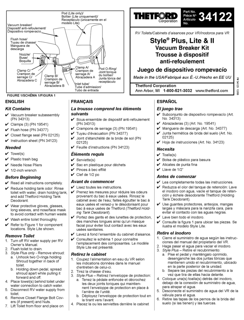
Thetford Style Plus Lite & II 34122 User manual

Thetford

Thetford Style Plus Lite & II 34122 User manual

Thetford 19833 User manual

Thetford

Thetford 19833 User manual

Thetford XR17200 User manual

Thetford

Thetford XR17200 User manual

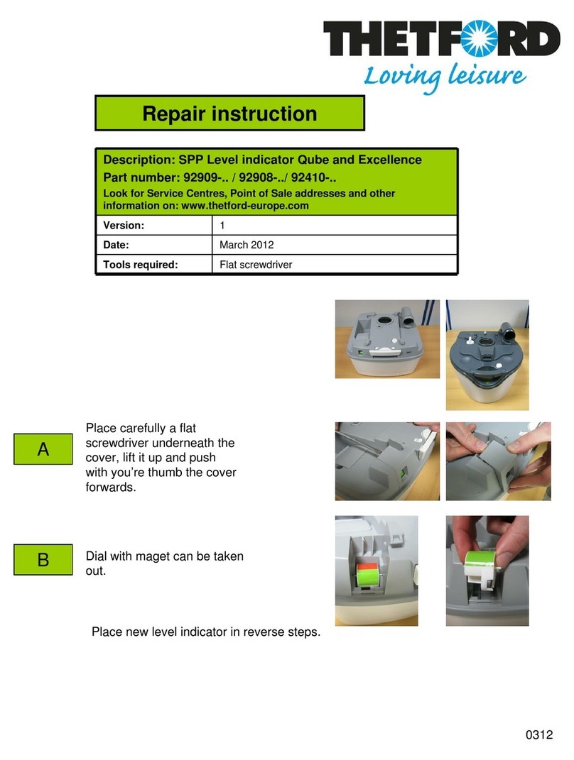
Thetford 92909 Series Setup guide

Thetford

Thetford 92909 Series Setup guide

Thetford EasyFit User manual

Thetford

Thetford EasyFit User manual

Thetford Aqua-Magic V User manual

Thetford

Thetford Aqua-Magic V User manual

Thetford 33226 User manual

Thetford

Thetford 33226 User manual

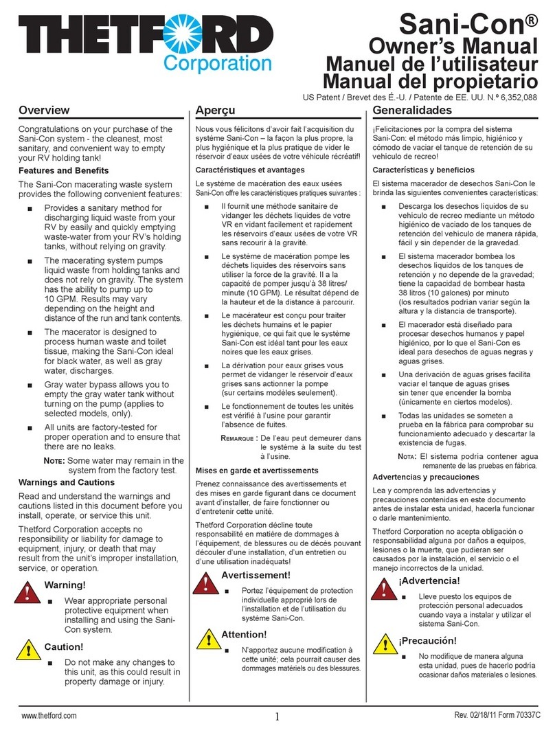
Thetford Sani-Con User manual

Thetford

Thetford Sani-Con User manual

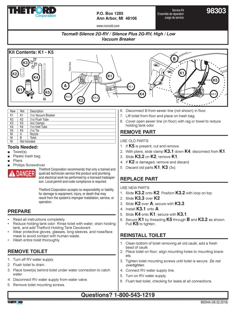
Thetford Tecma Silence 2G-RV User manual

Thetford

Thetford Tecma Silence 2G-RV User manual

Thetford C500 User manual

Thetford

Thetford C500 User manual

Thetford Sani-Con Turbo User manual

Thetford

Thetford Sani-Con Turbo User manual

Thetford 23709 Setup guide

Thetford

Thetford 23709 Setup guide

Thetford 100 Series User manual

Thetford

Thetford 100 Series User manual

Thetford ELECTRA MAGIC User manual

Thetford

Thetford ELECTRA MAGIC User manual

Thetford SmartTote User manual

Thetford

Thetford SmartTote User manual

Thetford Aqua-Magic 34120 User manual

Thetford

Thetford Aqua-Magic 34120 User manual

Thetford Aqua-Magic STYLE PLUS User manual
Thetford

Thetford Aqua-Magic STYLE PLUS User manual

Thetford Sanicon Turbo 500 User manual

Thetford

Thetford Sanicon Turbo 500 User manual

Thetford 2384978 Setup guide

Thetford

Thetford 2384978 Setup guide
Popular Plumbing Product manuals by other brands

Hans Grohe Versostat Unica Set 27171000 Instructions for use/assembly instructions

Hans Grohe

Hans Grohe Versostat Unica Set 27171000 Instructions for use/assembly instructions

Bristan CRZ2 SHXDIVCTFF C Installation instructions & user guide

Bristan

Bristan CRZ2 SHXDIVCTFF C Installation instructions & user guide

Omnires SL7732GR Installation and Maintenance

Omnires

Omnires SL7732GR Installation and Maintenance

Sanela SLW 02PA Mounting instructions

Sanela

Sanela SLW 02PA Mounting instructions

Moen 84402 Illustrated Parts

Moen

Moen 84402 Illustrated Parts

Franke PROTRONIC-S EPRTRS0028 Installation and operating instructions

Franke

Franke PROTRONIC-S EPRTRS0028 Installation and operating instructions

newform 27892 instructions

newform

newform 27892 instructions

American Standard NEO Traditional 6004S parts list

American Standard

American Standard NEO Traditional 6004S parts list

Creda 550C Handbook

Creda

Creda 550C Handbook

Schell EDITION 02 800 06 99 Assembly and installation instructions

Schell

Schell EDITION 02 800 06 99 Assembly and installation instructions

Crosswater Berea 11-01 installation instructions

Crosswater

Crosswater Berea 11-01 installation instructions

Moen 7800 Product user manual

Moen

Moen 7800 Product user manual

Raita BioBox M manual

Raita

Raita BioBox M manual

Sanela SLW 50 Mounting instructions

Sanela

Sanela SLW 50 Mounting instructions

Project Source F8FA0066CP manual

Project Source

Project Source F8FA0066CP manual

Moen ICON T964 Series Specifications

Moen

Moen ICON T964 Series Specifications

Sterling Plumbing ENSEMBLE 71100116 Specifications

Sterling Plumbing

Sterling Plumbing ENSEMBLE 71100116 Specifications

Kessel Ferrofix Express manual

Kessel

Kessel Ferrofix Express manual

manuals.online logo
manuals.online logoBrands
  • About & Mission
  • Contact us
  • Privacy Policy
  • Terms and Conditions

Copyright 2025 Manuals.Online. All Rights Reserved.