Thinkcar THINKSCAN Max User manual

EN
I
www.mythinkcar.com THINKSCAN Max
Content
1 Quick Start Manual..........................................................................................................1
1.1 Initial Use........................................................................................................................1
1.1.1 Turn on the Machine ...............................................................................................1
1.1.2 Language Setting....................................................................................................1
1.1.3 Connect WIFI ..........................................................................................................2
1.1.4 Choose Time Zone..................................................................................................2
1.1.5 User Agreement ......................................................................................................2
1.1.6 Create an Account ..................................................................................................3
1.1.7 Typing in Business Information ...............................................................................3
2 General information ........................................................................................................6
2.1 On-Board Diagnostics (OBD) II ......................................................................................6
2.2 Diagnostic Trouble Codes (DTCs)..................................................................................6
2.3 Data Link Connector (DLC) Location..............................................................................7
2.4 OBD II Readiness Monitors............................................................................................8
2.5 OBD II Monitor Readiness Status...................................................................................9
2.6 OBD II Defi nitions...........................................................................................................9
3 Introduction to the Product ..........................................................................................11
3.1 General introductions ...................................................................................................11
3.1.1 Diagnostic host .....................................................................................................11
3.1.2 Technical indications .............................................................................................12
4 Preparation.....................................................................................................................13
4.1 Charge the host............................................................................................................13
4.2 Battery ..........................................................................................................................13
4.3 Power on and off ..........................................................................................................13
4.3.1 Power on...............................................................................................................13
4.3.2 Power off ...............................................................................................................13
5 Functions Descriptions.................................................................................................14
5.1 Diagnosis......................................................................................................................14
5.2 Maintenance & Reset ...................................................................................................20
5.2.1 Maintenance light reset.........................................................................................21
5.2.2 Steering angle reset..............................................................................................21
5.2.3 Battery matching ...................................................................................................21
5.2.4 ABS exhaust .........................................................................................................21
5.2.5 Throttle matching ..................................................................................................22
5.2.6 Brake pad reset.....................................................................................................22
5.2.7 DPF regeneration..................................................................................................22
5.2.8 Anti-theft matching ................................................................................................22
5.2.9 Nozzle coding .......................................................................................................23
5.2.10 Tire pressure reset ..............................................................................................23

EN
II
www.mythinkcar.com
THINKSCAN Max
5.2.11 Suspension level calibration................................................................................23
5.2.12 Headlight matching .............................................................................................23
5.2.13 Gearbox matching...............................................................................................23
5.2.14 Sunroof initialization............................................................................................23
5.2.15 EGR Adaption .....................................................................................................24
5.2.16 Gear Learning .....................................................................................................24
5.2.17 ODO Reset .........................................................................................................24
5.2.18 Airbag Reset .......................................................................................................24
5.2.19 Transport Mode...................................................................................................24
5.2.20 A/F Reset ............................................................................................................25
5.2.21 Stop/Start Reset..................................................................................................25
5.2.22 NOx Sensor Reset ..............................................................................................25
5.2.23 AdBlue Reset (Diesel Engine Exhaust Gas Filter) ..............................................25
3.5.24 Seat Calibration ..................................................................................................25
5.2.25 Coolant Bleeding.................................................................................................25
5.2.26 Tyre Reset...........................................................................................................25
5.2.27 Windows Calibration ...........................................................................................25
5.2.28 Language Change ..............................................................................................25
5.3 ThinkFile.......................................................................................................................25
5.4 ThinkStore ....................................................................................................................26
5.5 Repair Info....................................................................................................................27
5.6 Software update ...........................................................................................................27
5.7 Settings.........................................................................................................................27
5.7.1 Account information ..............................................................................................27
5.7.2 Customer management ........................................................................................28
5.7.3 Business information.............................................................................................28
5.7.4 Network.................................................................................................................28
5.7.5 Firmware upgrade.................................................................................................28
6 Q&A.................................................................................................................................28
Warranty Terms.................................................................................................................29
EN
1
www.mythinkcar.com THINKSCAN Max
1 Quick Start Manual
1.1 Initial Use
The following settings should be made when you initially use the tool.
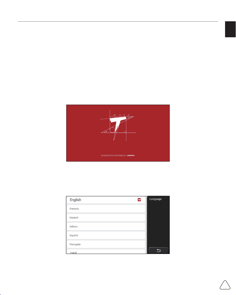
1.1.1 Turn on the Machine
After pressing the power button, images will be shown on the screen as follows.
1.1.2 Language Setting
Select the tool language from the languages displayed on the interface.
EN
2
www.mythinkcar.com
THINKSCAN Max
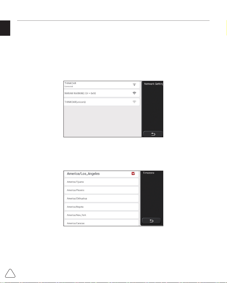
1.1.3 Connect WIFI
The system will automatically search all available WIFI networks and you can choose the
WIFI needed. If the chosen network is open, you can connect it directly; If the chosen
network is encrypted, you must enter the correct password. Then You can connect WIFI
after clicking “connect”.
Tips: Wi-Fi must be set. If no Wi-Fi network is available nearby, you can enable "Portable Mobile
Hotspot".
1.1.4 Choose Time Zone
Choose the time zone of the current location, then the system will automatically cofi gure
the time according to the time zone you chose.
1.1.5 User Agreement
Please read all the terms and conditions of the user agreement carefully. Choose “Agree
all the above terms”, and click the “Agree” button to complete the registration process.
Then the page will jump to the “Congratulations on your successful registration” interface.

EN
3
www.mythinkcar.com THINKSCAN Max
Initial settings are finished after the above steps. It will automatically jump to the work
interface after 3 seconds.
1.1.6 Create an Account
You need to register an account through your e-mail box. If you have owned other products
of THINK series, you can directly log in by using the account available.
1.1.7 Typing in Business Information
Typing in the repair shop information, which will be shown in the diagnostic report.

EN
4
www.mythinkcar.com
THINKSCAN Max
Copyright Information
Copyright Information Copyright © 2020 by THINKCAR TECH. CO., LTD. All rights
reserved. No part of this publication may be reproduced, stored in a retrieval system,
or transmitted in any form or by any means, electronic, mechanical, photocopying and
recording or otherwise, without the prior written permission of THINKCAR. The information
contained herein is designed only for the use of this unit. THINKCAR is not responsible
for any use of this information as applied to other units. Statement: THINKCAR owns the
complete intellectual property rights for the software used by this product. For any reverse
engineering or cracking actions against the software, THINKCAR will block the use of this
product and reserve the right to pursue their legal liabilities.
Trademark Information
THINKSCAN Max is a registered trademark of THINKCAR TECH CO., LTD. All other
THINKSCAN Max trademarks, service marks, domain names, logos, and company names
referred to in this manual are either trademarks, registered trademarks, service marks,
domain names, logos, company names of or are otherwise the property of THINKCAR or
its affi liates. In countries where any of the THINKSCAN Max trademarks, service marks,
domain names, logos and company names are not registered, THINKSCAN Max claims
other rights associated with unregistered trademarks, service marks, domain names,
logos, and company names. Other products or company names referred to in this manual
may be trademarks of their respective owners. You may not use any trademark, service
mark, domain name, logo, or company name of THINKTOOL or any third party without
permission from the owner of the applicable trademark, service mark, domain name,logo,
or company name. You may contact THINKCAR TECH INC by visiting the website at www.
mythinkcar.com, or writing to THINKCAR TECH CO., LTD.
General Notice
• Other product names used herein are for identification purposes only and may be
trademarks of their respective owners. THINKCAR disclaims any and all rights in those
marks.
• There is a possibility that this unit is inapplicable to some of the vehicle models or
systems listed in the diagnosis section due to diff erent countries, areas, and/or years.
Do not hesitate to contact THINKCAR if you come across such questions. We are to
help you solve the problem as soon as possible.
Disclaimer
• To take full advantage of the unit, you should be familiar with the engine.
• All information, illustrations, and specifi cations contained in this manual are based on
the latest information available at the time of publication. The right is reserved to make

EN
5
www.mythinkcar.com THINKSCAN Max
change at any time without notice.
• Neither THINKCAR nor its affi liates shall be liable to the purchaser of this unit or third
parties for damages, losses, costs or expenses incurred by purchaser or third parties
as a result of: accident, misuse, or abuse of this unit, or unauthorized modifications,
repairs, or alterations to this unit, or failure to strictly comply with THINKCAR operating
and maintenance instructions.
• THINKCAR shall not be liable for any damages or problems arising from the use of any
options or any consumable products other than those designated as Original THINKCAR
• Products or THINKCAR Approved Products by THINKCAR.
Safety Precautions and Warnings
To prevent personal injury or damage to vehicles and/or this tool, please read this user’s
manual fi rst cafully and observe the following safety precautions at a minimum whenever
working on a vehicle:
• Always perform automotive testing in a safe environment.
• Do not attempt to operate or observe the tool while driving a vehicle. Operating or
observing the tool will cause driver distraction and could cause a fatal accident.
• Wear safety eye protection that meets ANSI standards.
• Keep clothing, hair, hands, tools, test equipment, etc. away from all moving or hot
engine parts.
• Operate the vehincle in a well-ventilated work area: Exhaust geses are poisonous.
• Put blocks in front of the drive wheels and never leave the vehicle unattended while
running tests.
• Use extreme caution when working around the ignition coil, distributor cap, ignition wires
and spark plugs.These components create hazardous voltages when the engine is
running.
• Put the transmission in P(for A/T)or N (for M/T)and make sure the parking brake is
engaged.
• Keep a fi re extinguisher suitable for gasoline/chemical/ electrical fi res nearby.
• Don't connect or disconnect any test equipment while the ignition is on or the engine is
running
• Keep this tool dry, clean, free from oil/water or grease. Use a mild detergent on a clean
cloth to clean the outside of the tool. when necessary.
• Please use the DC 5V power adaptor to charge this tool. No responsibility can be
assumed for any damage or loss caused as a result of using power adaptors other than
the night one.
An Introduction to the company
THINKCAR TECH is a highly creative developer of vehicle diagnosis tools. By marrying

EN
6
www.mythinkcar.com
THINKSCAN Max
user-friendly creative ideas with technologies, the company has produced Think series
products featured as ultimate experience and extraordinary imagination, including
THINKOBD, THINKCAR, THINKDIAG, THINKPLUS, THINKSCAN and THINKTOOL.
Those products prove to be a brand new generation of diagnosis tools through user-
oriented creative products forms and service system. THINKCAR TECH keeps striving for
perfection in all aspects such as its products design, material selection, manufacturing and
software service.
2 General information
2.1 On-Board Diagnostics (OBD) II
The first generation of On-Board Diagnostics (OBD I) was developed by the California
Air Resources Board (ARB) and implemented in 1988 to monitor some of the emission
control components on vehicles. As technology evolved and the desire to improve the On-
Board Diagnostic system increased, a new generation of On-Board Diagnostic system
was developed. This second generation of OnBoard Diagnostic regulations is called “OBD
II”. The OBD II system is designed to monitor emission control systems and key engine
components by performing either continuous or periodic tests of specifi c components and
vehicle conditions. When a problem is detected, the OBD II system turns on a warning
lamp (MIL) on the vehicle instrument panel to alert the driver typically by the phrase of
“Check Engine” or “Service Engine Soon”. The system will also store important information
about the detected malfunction so that a technician can accurately find and fix the
problem. Here below follow three pieces of such valuable information:
1) Whether the Malfunction Indicator Light (MIL) is commanded ‘on’ or ‘off ’;
2) Which, if any, Diagnostic Trouble Codes (DTCs) are stored;
3) Readiness Monitor status.
2.2 Diagnostic Trouble Codes (DTCs)
OBD II Diagnostic Trouble Codes are codes that are stored by the on-board computer
diagnostic system in response to a problem found in the vehicle. These codes identify a
particular problem area and are intended to provide you with a guide as to where a fault
might be occurring within a vehicle. OBD II Diagnostic Trouble Codes consist of a fi ve-
digit alphanumeric code. The fi rst character, a letter, identifi es which control system sets
the code. The second character, a number, 0-3; other three characters, a hex character,
0-9 or A-F provide additional information on where the DTC originated and the operating
conditions that caused it to set. Here below is an example to illustrate the structure of the
digits:

EN
7
www.mythinkcar.com THINKSCAN Max
DTC Example
P0201
Systems
P=Powertrai
B=Body
C=Chassis
U=Network
ldentifies what section of the
system is malfunctioning
Code Type
0- Generic(SAE)
1 - Manufacturer Specifi c
2- Generic ('P”Codes) and
Manufacturer
Specifi c ("B”,“C”and
“U”Codes)
3- Includes both Generic
and Manufacturer
Specifi c Codes
Sub-systems
Identifies the system where the
problem is located.“P”Code systems
are listed below.“B”,“C”and“U”Code
system will vary.
0 - Fuel and air metering; Auxiliary
emlssion controls
1 - Fuel and air metering
2 - Fuel and air metering (injector
circuit malfunction only)
3 - Ignition system or misfi re
4 - Auxiliary emission control system
5 - Vehicle speed control and idl
control system
6 - Computer output circuits
7 - Transmission
8 - Transmission
9 - Transmission
A - Hybrid Propulsion
B - Hybrid Propulsion
C - Hybrid Propulsion
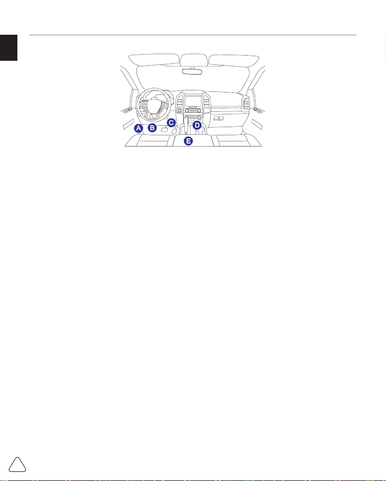
2.3 Data Link Connector (DLC) Location
The DLC (Data Link Connector or Diagnostic Link Connector) is typically a 16pin connector
where diagnostic code readers interface with the vehicle’s onboard computer. The DLC is
usually located 12 inches from the center of the instrument panel (dash), under or around
the driver’s side for most vehicles. If Data Link Connector is not located under dashboard,
a label should be there telling location. For some Asian and European vehicles, the DLC
is located behind the ashtray and the ashtray must be removed to access the connector. If
the DLC cannot be found, refer to the vehicle’s service manual for the location.
EN
8
www.mythinkcar.com
THINKSCAN Max
2.4 OBD II Readiness Monitors
An important part of a vehicle’s OBD II system is the Readiness Monitors, which are
indicators used to fi nd out if all of the emissions components have been evaluated by the
OBD II system. They are running periodic tests on specifi c systems and components to
ensure that they are performing within allowable limits.
Currently, there are eleven OBD II I Readiness Monitors (or I/M Monitors) defi ned by the
U.S. Environmental Protection Agency (EPA). Not all monitors are supported in every
vehicles and the exact number of monitors in any vehicle depends on the motor vehicle
manufacturer's emissions control strategy.
Continuous Monitors -- Some of the vehicle components or systems are continuously
tested by the vehicle's OBD II system, while others are tested only under specifi c vehicle
operating conditions. The continuously monitored components listed below are always
ready:
1. Misfi re
2. Fuel System
3. Comprehensive Components (CCM)
Once the vehicle is running, the OBD II system is continuously checking the above
components, monitoring key engine sensors, watching for engine misfi re, and monitoring
fuel demands.
Non-Continuous Monitors -- - Unlike the continuous monitors, many emissions and engine
system components require the vehicle to be operated under specifi c conditions before the
monitor is ready. These monitors are termed noncontinuous monitors and are listed below:
1) EGR System
2) O2 Sensors
3) Catalyst
4) Evaporative System
5) O2 Sensor Heater
6) Secondary air Injection
7) Heated Catalyst

EN
9
www.mythinkcar.com THINKSCAN Max
2.5 OBD II Monitor Readiness Status
OBD II systems must indicate whether or not the vehicle’s PCM’s monitor system has
completed testing on each component. Components that have been tested will be reported
as “Ready”, or “Complete”, meaning they have been tested by the OBD II system.
The purpose of recording readiness status is to allow inspectors to determine if the
vehicle’s OBD II system has tested all the components and/or systems. The Powertrain
Control Module (PCM) sets a monitor to “Ready” or “Complete” after an appropriate drive
cycle has been performed. The drive cycle that enables a monitor and sets readiness
codes to “Ready” varies for each individual monitor. Once a monitor is set as “Ready”
or “Complete”, it will remain in this state. A number of factors, including erasing of
Diagnostic Trouble Codes (DTCs) with a code reader or a disconnected battery, can result
in Readiness Monitors being set to “Not Ready”. Since the three continuous monitors
are constantly evaluating, they will be reported as “Ready” all of the time. If testing of a
particular supported non-continuous monitor has not been completed, the monitor status
will be reported as “Not Complete” or “Not Ready.”
In order for the OBD monitor system to become ready, the vehicle should be driven under
a variety of normal operating conditions. These operating conditions may include a mix of
highway driving and stop and go, city type driving, and at least one overnight-off period.
For specific information on getting your vehicle’s OBD monitor system ready, please
consult your vehicle owner’s manual.
2.6 OBD II Defi nitions
Powertrain Control Module (PCM) -- OBD II terminology for the on-board computer that
controls engine and drive train.
Malfunction Indicator Light (MIL) -- Malfunction Indicator Light (Service Engine Soon,
Check Engine) is a term used for the light on the instrument panel. It is to alert the driver
and/or the repair technician that there is a problem with one or more of vehicle’s systems
and may cause emissions to exceed federal standards. If the MIL illuminates with a steady
light, it indicates that a problem has been detected and the vehicle should be serviced
as soon as possible. Under certain conditions, the dashboard light will blink or fl ash. This
indicates a severe problem and fl ashing is intended to discourage vehicle operation. The
vehicle onboard diagnostic system cannot turn the MIL off until the necessary repairs are
completed or the condition no longer exists.
DTC -- Diagnostic Trouble Codes (DTC) that identifies which section of the emission
control system has malfunctioned.
Enabling Criteria -- Also termed Enabling Conditions. They are the vehiclespecifi c events
or conditions that must occur within the engine before the various monitors will set, or
run. Some monitors require the vehicle to follow a prescribed “drive cycle” routine as part

EN
10
www.mythinkcar.com
THINKSCAN Max
of the enabling criteria. Drive cycles vary among vehicles and for each monitor in any
particular vehicle. Please refer to the vehicle's factory service manual for specifi c enabling
procedures.
OBD II Drive Cycle -- A specific mode of vehicle operation that provides conditions
required to set all the readiness monitors applicable to the vehicle to the “ready” condition.
The purpose of completing an OBD II drive cycle is to force the vehicle to run its onboard
diagnostics. Some form of a drive cycle needs to be performed after DTCs have been
erased from the PCM’s memory or after the battery has been disconnected. Running
through a vehicle’s complete drive cycle will “set” the readiness monitors so that future
faults can be detected. Drive cycles vary depending on the vehicle and the monitor that
needs to be reset. For vehicle specifi c drive cycle, consult the service manual.
Freeze Frame Data -- When an emissions related fault occurs, the OBD II system not
only sets a code but also records a snapshot of the vehicle operating parameters to help
in identifying the problem. This set of values is referred to as Freeze Frame Data and may
include important engine parameters such as engine RPM, vehicle speed, air fl ow, engine
load, fuel pressure, fuel trim value, engine coolant temperature, ignition timing advance, or
closed loop status.
Fuel Trim (FT) -- Feedback adjustments to the base fuel schedule. Short-term fuel trim
refers to dynamic or instantaneous adjustments. Long-term fuel trim refers to much more
gradual adjustments to the fuel calibration schedule than short-term trim adjustments.
These long-term adjustments compensate for vehicle differences and gradual changes
that occur over time.
8) A/C system

EN
11
www.mythinkcar.com THINKSCAN Max
3 Introduction to the Product
3.1 General introductions
THINKSCAN Max, one of the diagnostic products launched by THINKCAR TECH INC, is
the highest-level OBD product of the THINK series for DIY users. Equipped with Android
operating system, it features powerful functions and can be updated online. Moreover, full
communication protocols make it cover a wider range of vehicle models.
Through the simple Bluetooth communication between diagnostic dongle and the host
computer, it achieves full car model and full system vehicle trouble diagnosis, which
include Reading DTCs, Clearing DTCs, Reading Data Stream, Actuation Test and Special
Functions.
3.1.1 Diagnostic host
1 2
4
6
5
3

EN
12
www.mythinkcar.com
THINKSCAN Max
1. Power inlet
Connect a charger for charging or data transmission.
2. USB expansion slot
3. Power source/Lock screen button
When the host is off , turn on it by pressing the button for 3 seconds.
When the host is on, press the button to wake up the screen or turn off the screen.
Turn off the host by pressing the button for over 3 seconds; force a shut down by
pressing the button for over 8 seconds.
4. Loudspeaker
5. Screen
6. Diagnostic dongle
It is pre-installed in the docking slot on the bottom of the host computer. Use the hand to
press the dongle once, it will be automatically ejected from the docking slot. When it is
not in use, please reinsert it into the slot to avoid loss.
3.1.2 Technical indications
The host product package includes a host, a diagnostic dongle, a charging cable, and a
power adapter. The following are performance parameters.
THINKSCAN Max host computer
• Battery Capacity:3100mAh/7.6V
• Screen Size: 5.99 inches
• Resolution: 720*1440 pixel
• Working Voltage: 5V
• Working Current: ≤2.5A
• Working Environment: 32 ℉ ~122 ℉ (0℃ ~50℃ )
• Storage Environment: -4 ℉ ~140 ℉ (-20℃ ~60℃ )
THINKSCAN Max Diagnostic Dongle
• Working Voltage: 12V
• Working Current: ≤60mA
• Working Environment: 14 ℉~122 ℉(-10℃~50℃)
• Storage Environment: -4 ℉~140 ℉(-20℃~60℃)

EN
13
www.mythinkcar.com THINKSCAN Max
4 Preparation
4.1 Charge the host
Follow the steps below to charge the host:
1. Connect one end of the power cord to the USB socket of the power adapter.
2. Connect the other end to the charging jack on the bottom of the host.
3. Plug the charger power plug into a power outlet to start charging.
When the battery status icon displays , the host has been charged. When it displays
the charging process has been completed and you shall disconnect the host.
4.2 Battery
• It is normal that the host won't turn on when charging because the battery has not been
used for a long time or it is exhausted. Please turn on the host again after charging the
battery for a while.
• Please charge the host through the charger in the package. The company assumes
no responsibility for damages and losses caused by charging with chargers other than
those specifi ed by the company.
• The battery can be recharged repeatedly. However, as the battery is wearable, the
standby time of the device will be shortened after long-time use. Please avoid frequent
repeated charging so as to extend battery life.
• The battery charging time varies with temperature and battery status.
• When the battery power is low, the system will pop up a prompt reminding you to
connect the charger. When the battery power is too low, the device will turn off .
4.3 Power on and off
4.3.1 Power on
Long press the power button and then the start interface will appear.
Tips: The device may fail to turn on if you use it for the fi rst time or haven't used it for a long time.
This may be caused by too low battery power. Please try to turn it on again after charging the device
for a while.
4.3.2 Power off
Long press the power button until the dialog box pops up, and then turn off the device
according to the prompts. If you need to force shutdown, long press the power button for
more than 8 seconds until the screen goes dark.

EN
14
www.mythinkcar.com
THINKSCAN Max
5 Functions Descriptions
The THINKSCAN Max host computer have 8 functions, namely, OBD, Scan, Maintenance
& Service, ThinkFile, ThinkStore, Repair Info, Setup and Update.
5.1 Diagnosis
Full system diagnosis: it supports more than 100 automobile brands, smart diagnosis
and traditional diagnosis covering OBD II full-function diagnosis, full-system and full-
function diagnosis: read fault codes, clear fault codes, read real-time data streams, special
functions, motion tests, etc.. A diagnostic report will be automatically generated after the
diagnosis.
Smart diagnosis
Plug the dongle into the vehicle's DLC port, then click “Scan” on the main interface. Then,
click "AUTOSEARCH" to start communicating with the dongle via Bluetooth. After a good
communication is established, the system starts reading the vehicle VIN.
Tips: if communication failure occurs, a prompt message box will pop up on the screen. Follow the
on-screen prompts to proceed.
If it fails to read VIN, you need to enter VIN manually.

EN
15
www.mythinkcar.com THINKSCAN Max
Diagnosis starts
1. Choose test mode: after reading VIN, the screen will enter the test mode selection
interface:
A. Health Report: this mode is to quickly check the vehicle and display the vehicle health
report (it’s available only when the the diagnosis software support this function). After
clicking “quick test”, the system starts scanning DTC respectively and show the result.

EN
16
www.mythinkcar.com
THINKSCAN Max
If you want to pause the scan, click “Pause”.
After the scan is over, the system will display the diagnostic report directly. The DTC can
be hidden by clicking the button after it.
The system with DTC will be displayed on the screen in red font, and the specifi c number
of DTC will be shown. A DTC-free system will be displayed as "OK".
Click the system name to see the specifi c defi nition of the DTC.
B. System Scan: automatically scan all systems of the vehicle.
C. System Selection: manually choose the automotive electronic control system.
2. Choose the system: Click “PCM” (e.g.), and the screen will enter selection interface.
3. Choose the function: click the function to be tested.

EN
17
www.mythinkcar.com THINKSCAN Max
Tips: The diagnosis menu varies with diff erent vehicles.
A. Version Information
As shown in the picture, click “Version Information” to read the current version information
of the car ECU.
B. Read Fault Code
This function is to read the DTC in the ECU memory , helping maintenance personnel to
quickly identify the cause of the vehicle breakdown.
Tips: Reading the DTC when troubleshooting a vehicle is only a small step in the entire diagnostic
process. Vehicle DTC are for reference only, and parts cannot be replaced directly based on the
given DTC defi nition. Each DTC has a set of test procedures. The maintenance technician must
strictly conform to the operation instructions and procedures described in the car maintenance
manual to confi rm the root cause of the breakdown.
As shown below, click “Read Fault Code”, and then the screen will display diagnostic
results.
Screen buttons:
Freeze frame: If this button is highlighted, it means there is freeze frame information. The
freeze frame serves to record some specifi c data streams at the moment when the car
breaks down. The number is for verifi cation.
Report: Save the current diagnosis result as a diagnosis report. The diagnostic report is
saved in the ThinkFile module and can be sent to designated e-mail boxes.

EN
18
www.mythinkcar.com
THINKSCAN Max
Tips: After the report is produced, the technician can take a real-time photo of the vehicle and save
it as a vehicle maintenance fi le.
C. Clear Fault Code
This function serves to clear the DTC of the ECU memory of the tested system.
Click “Clear Fault Code”, and then the system can automatically delete the existing DTC
and pop up the dialogue box saying “DTC successfully cleared”.
Note: For general vehicles, please strictly follow the normal sequence: read the DTC , clear it, have
a test run, read the DTC again for verifi cation, repair the vehicle, clear the DTC, and try again to
confi rm that the DTC no longer appear.
D. Read Data Stream
This function is majorly used to read and display real-time data and parameters of the car
ECU. Through observing these data streams, maintenance technicians can understand
the vehicle’s overall performance and off er maintenance suggestions.
Screen buttons:
Select all: If you want to check some data stream, tick the box before its name. If you want
to choose all the data streams, click this button.
Deselect: Click this button to deselect all checked data streams.
OK: Confi rm current operations. Click "OK" after selection, and then the system will display
the dynamic data of selected data streams.
Screen buttons:
This manual suits for next models
1
Table of contents
Languages:
Other Thinkcar Diagnostic Equipment manuals

Thinkcar
Thinkcar X10 User manual

Thinkcar
Thinkcar THINKOBD 100 User manual

Thinkcar
Thinkcar ThinkTool PD8 User manual

Thinkcar
Thinkcar THINKTPMS G1 User manual

Thinkcar
Thinkcar TKTT3 Instruction manual

Thinkcar
Thinkcar THINKOBD 500 User manual

Thinkcar
Thinkcar ADAS User manual

Thinkcar
Thinkcar TK-IMT602 User manual


