THORLABS SPCM A Series User manual

Single Photon Counting Module
SPCMxxA
Operation Manual
2019

Version:
Date: 1.2
27-May-2019

Foreword
Contents 3
1 General Information 4
41.1 Safety 41.2 Ordering Codes and Accessories 51.3 Requirements 51.3.1 Hardware Requirements 51.3.2 Software Requirements 51.3.3 Interface Requirements
2 Installation 6
62.1 Parts List 62.2 Getting Started 62.3 Installing Software
3 Operating Instructions 10
103.1 Operating Principle 113.2 Functional Block Diagram 123.3 Connecting the SPCM 133.4 Graphic User Interface (GUI) 133.4.1 Menu "File" 153.4.2 Menu "Device" 163.4.3 Menu "Option" 163.4.4 Menu "Help" 173.4.5 Menu Icons 183.4.6 Functional Area 193.4.6.1 Alignment Display 203.4.6.2 Table Display 203.4.6.3 Graph Display 213.4.6.4 Bar Display 223.5 Operating Modes 223.5.1 Manual Mode 233.5.2 Free Running Timed Counter 253.5.3 Externally Triggered Timed Counter 273.5.4 Externally Triggered Counter 293.5.5 External Gating
4 SCPI Commands 31
5 Maintenance and Service 38
385.1 Version Information 395.2 SPCM Firmware Update 395.2.1 Installing DFU Wizard

425.2.2 Firmware Update 465.3 Troubleshooting
6 Appendix 48
486.1 Typical Spectral Responsivity 486.2 Definitions 506.3 Pulse Out 516.4 Technical Data 526.5 Dimensions 546.6 Certifications and Compliances 556.7 Warranty 556.8 Exclusion of Reliability and Copyright 566.9 Thorlabs 'End of Life' Policy (WEEE) 576.10List of Acronyms 586.11Thorlabs Worldwide Contacts

We aim to develop and produce the best solution for your application
in the field of optical measurement technique. To help us to live up to
your expectations and constantly improve our products we need
your ideas and suggestions. Therefore, please let us know about
possible criticism or ideas. We and our international partners are
looking forward to hearing from you.
Thorlabs GmbH
WARNING
Sections marked by this symbol explain dangers that might result in
personal injury or death. Always read the associated information
carefully, before performing the indicated procedure.
Please read this advice carefully!
This manual also contains "NOTES" and "HINTS" written in this form.
ATTENTION
Paragraphs preceded by this symbol explain hazards that could
damage the instrument and the connected equipment or may cause
loss of data.
NOTE
3© 2019 Thorlabs

4
SPCMxxA
© 2019 Thorlabs
1 General Information
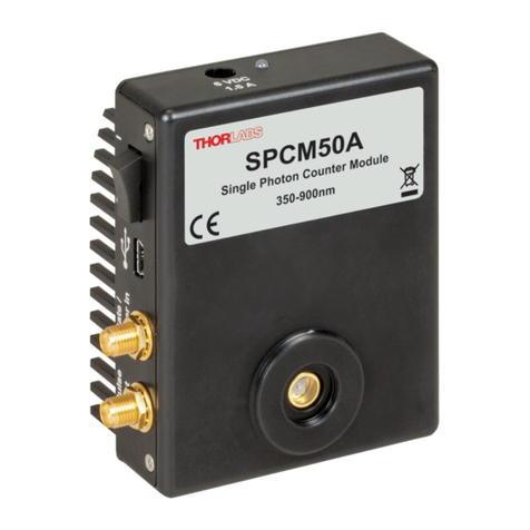
Thorlabs' Single Photon Counter Modules use a silicon avalanche photodiode to detect single
photons. The SPCM counters are sensitive to photons emitted in the 350 to 900 nm range with
the maximum sensitivity at 500 nm. They work by converting an incoming photon into a TTL
pulse in the detector, which is counted by the internal 31-bit counter. An additional SMA con-
nection offers a direct output pulse signal from the module that can be viewed on an oscillo-
scope or connected to an external counter.
An integrated Peltier element stabilizes the diode's temperature below the ambient temperature
to reduce the dark count rate. The two available models, SPCM20A and SPCM50A, have low
typical dark count rates of 25 and 150 counts per second, respectively, which allows them to
detect power levels down to 0.14 fW.
The active quenching circuit integrated into the diode of the SPCM enables high count rates. Its
high speed allows users to count a photon every 35 - 45 ns, depending on the model chosen.
The SPCM20A provides an active area of Ø20 µm and the SPCM50A offers Ø50 µm.
The SPCM includes a software package with GUI for out-of-the-box operation.
1.1 Safety
Attention
The safety of any system incorporating the equipment is the responsibility of the assem-
bler of the system.
All statements regarding safety of operation and technical data in this instruction manual
will only apply when the unit is operated correctly as it was designed for.
The SPCMxxA must not be operated in explosion endangered environments!
Do not remove covers!
Do not open the cabinet. There are no parts serviceable by the operator inside!
This precision device is only serviceable if properly packed into the complete original
packaging including the plastic foam sleeves. If necessary, ask for replacement pack-
aging.
Refer servicing to qualified personnel!
Only with written consent from Thorlabs may changes to single components be made or
components not supplied by Thorlabs be used.
All modules must only be operated with proper shielded connection cables.
1.2 Ordering Codes and Accessories
Imperial versions:
SPCM20A Single Photon Counter Module, 350-900 nm, 20 µm active area
SPCM50A Single Photon Counter Module, 350-900 nm, 50 µm active area
Metric versions
SPCM20A/M Single Photon Counter Module, 350-900 nm, 20 µm active area, metric
SPCM50A/M Single Photon Counter Module, 350-900 nm, 50 µm active area, metric
1 General Information
© 2019 Thorlabs 5
1.3 Requirements
1.3.1 Hardware Requirements
·CPU: 1 GHz or higher
·RAM: 256 MB free space
·Graphic card with at least 32 MB memory
·Hard disc with at least 100 MB free storage space
·Free USB2.0 port (USB2.0 Full Speed; High Speed recommended)
·USB cable according the USB 2.0 specification
1.3.2 Software Requirements
This software was verified with the following platforms:
- Windows®XP (32-bit version)
- Windows®Vista (32-bit version)
- Windows®Vista x64 Edition (64-bit version)
- Windows®7 (32-bit version)
- Windows®7 x64 Edition (64-bit version)
- Windows®10 (32-bit, 64-bit)
1.3.3 Interface Requirements
For full functionality it is recommended to use USB 2.0 High Speed interface.

6
SPCMxxA
© 2019 Thorlabs
2 Installation
2.1 Parts List
Inspect the shipping container for damage.
If the shipping container seems to be damaged, keep it until you have inspected the contents
and you have inspected the SPCMxxA mechanically and electrically.
Verify that you have received the following items within the package:
1. SPCM20A (~/M) or SPCM50A (~/M)
2. Wall plug adapter (power supply 100-240 VAC / 6 VDC / 1.5 A)
3. USB 2.0 cable, A to mini B
4. Quick Start
5. CD with operating software
2.2 Getting Started
NOTE
Take care for proper air ventilation in order to ensure normal operation of the SPCMxxA.
Prior to connecting the SPCMxxA to a PC, please install software from the attached CD.
2.3 Installing Software
NOTE
The screenshots in this manual are related to a Windows®7 Operating System.
Insert the CD into your CD or DVD drive. If the installation screen does not appear automati-
cally, please execute
[CD Drive]:\Autorun\autorun.exe
NOTE
A NI-VISA Runtime Engine®is required to operate the Single Photon Counter. If NI-VISA is not
installed yet, the installation package will install version 5.0.3 automatically.
Start installation by clicking "Single Photon Counter Software"

2 Installation
© 2019 Thorlabs 7
Click "Next" to continue
In the next two screens, click "I accept..." if you do so, then "Next"

8
SPCMxxA
© 2019 Thorlabs
Click "Next" to continue.
After finishing the installation, the installation summary will be displayed. Click "Finish" to con-
tinue.

2 Installation
© 2019 Thorlabs 9
After completing the installation you might be prompted to restart your PC.

10
SPCMxxA
© 2019 Thorlabs
3 Operating Instructions
3.1 Operating Principle
The Thorlabs SPCMxxA uses a silicon avalanche photo diode (Si APD), operated in reverse di-
rection and biased slightly beyond the breakdown threshold voltage VBR (see diagram below,
point A), also known as avalanche voltage.
This operating mode is also known as "Geiger mode". An APD in Geiger mode will remain in a
metastable state until a photon arrives and generates free charge carriers in the PD's junction.
These free charge carriers trigger an avalanche (point B), leading to a significant current. An
active quenching circuit integrated into the APD limits the current through the APD in order to
avoid destruction and lowers the bias voltage below the breakdown voltage VBR (point C) im-
mediately after a photon released an avalanche, this way enabling high count rates (dead time
between counts down to 35 - 45ns). Afterwards the bias voltage is being restored.
During the quenching time, which is known as the dead time of the diode, the APD is insensit-
ive to any other incoming photons.
Spontaneously triggered avalanches are possible while the diode is in a metastable state. If
these spontaneous avalanches occur randomly, they are called dark counts. An integrated
Peltier element stabilizes the diode’s temperature below the ambient temperature to reduce the
dark count rate. For long-term temperature stability, a fan is built in.
In case the spontaneously triggered avalanches are correlated in time with a pulse caused by a
photon, it is called an afterpulse. To ignore such afterpulses in the measurement, an additional
Pulse Blind Time can be set in the software, which will cause the internal counter of the SPCM
to ignore all pulses occurring during the set pulse blind time. This additional Pulse Blind Time
starts at the moment when a photon was registered by the counter.
Note
Due to APD properties, single photons may be not counted, i.e., lost. Possible reasons are the
APD's intrinsic dead time during quenching, an additionally set blind time of the SPCM and the
APD's nonlinearity.

3 Operating Instructions
© 2019 Thorlabs 11
3.2 Functional Block Diagram
The current pulse generated by an incoming photon passes a pulse shaping circuit, which is
shortening the APD's output TTL pulse duration from 35 ... 45 ns to ~ 14 ns. These pulse are
applied to the SMA "Pulse Out" connector and to the internal 31-bit counter. The counter state
is read out via the USB connection.
The counter can be operated in timed mode, here an programmable timer defines the counting
time ("Bin Length") and the interval between subsequent counts ("Time between Bins"). Altern-
atively, the counter can be started directly from the PC software (Manual Mode) or by an ex-
ternal trigger signal. An internal buffer can save up to 4000 counts in order to comply with an in-
sufficient USB transfer rate.
A special operating mode (External Gating mode) allows to control the APD bias voltage ex-
ternally - in this mode, the external signal applied to the "Gate / Trigger In" enables the APD
Geiger mode and controls the counter.
The SPCM operating modes are explained in detail in section Operating Modes .
On the "Pulse Out" terminal the signal from the pulse shaper is applied so that counts can be
viewed on an oscilloscope or registered by an external counter.
Via the USB interface, the SPCM can be controlled (Start / Stop measurement, change oper-
ating modes and settings etc.) and measurement data are transferred, as well as status inform-
ation and error indications.
The SCPMxxA is powered by an external wall-plug power supply (100-240 VAC / 6 VDC /
1.5A).
Note
"Gate / Trigger In" and "Pulse Out" are of a 50 Wimpedance. Make sure that the trigger pulse
source is capable to work on a 50 Wload and that the device connected to "Pulse Out" oper-
ates at a 50 Winput impedance.
The SCPMxxA comes with factory default setting to External Gating Mode .
22
29

12
SPCMxxA
© 2019 Thorlabs
3.3 Connecting the SPCM
- Connect the wall plug adapter to mains outlet
- Connect the adapter’s DC output cable to the SPCMxxA
- Connect the SPCMxxA via the USB cable to your PC
- Switch on the single photon counter module. The green LED, located beside the DC power
input of the SPCMxxA, lights up.
Note
During a measurement, the green status LED is switched off in order to avoid stray light.
- Your operating system will recognize a new hardware and automatically start the driver in-
stallation.
- After completing, a message will inform you that the new hardware is installed and ready to
use.
Start the software by clicking the appropriate icon on the desktop; alternatively it can be
started from Windows button - Programs - Thorlabs - SPCM Series Software - “SPCM”.
As a next step, the Single Photon Counter Module needs to be connected to software. There-
fore, click to the icon in the toolbar or choose the appropriate function from the Device
menu
A device selection dialog opens
The selected device is shown on a colored background. Click "Connect" - the selected hard-
ware is connected and the dialog window closes.
If no device is shown to be selected, click "Refresh Device List" button. Select the recognized
device and click "Connect".
Note
Multiple SPCM devices can be operated from a single PC by running a separate software in-
stance. The Device Dialog panel will show all recognized SPCM devices, an already connected

3 Operating Instructions
© 2019 Thorlabs 13
SPCM will be inactive (grayed out), so that only a free, available SPCM can be selected to con-
nect.
3.4 Graphic User Interface (GUI)
At the first start of the GUI or after selecting "Default Settings" (Menu "Option" -> "Settings") the
following default measurement settings are loaded:
·Operating Mode: Free Running Timed Counter
·Bin length: 100 ms
·Time between bins: 0.001 ms
·Pulse blind time: 0.000 ns
·Array Measurement continuously: No (single)
·Bins per array: 100
The GUI comes with verbal menus and icons:
3.4.1 Menu "File"
The File menu allows to Save and Load measurement results with the appropriate settings. The
most recent measurement can be saved also if the SPCM was disconnected from the GUI.
Measurement results can be loaded with no SPCM connected, this way reproducing measure-
ment results with the settings at which these measurements were made.
Import / Export Settings handles only settings, no measurement results. This is a useful feature
to easily reproduce older measurement conditions, e.g. for comparison.

14
SPCMxxA
© 2019 Thorlabs
Example of saved data:
Thorlabs Single Photon Counter Data Export
Date (YYYY-MM-DD): 2011-07-11
Time (HH:MM:SS): 15:58:52
Device Name: SPCM50A
Serial Number: M00260815
GUI Revision: 0.9 Build 117
Driver Revision: 0.8.8
Firmware Revision: 0.10.0
Application settings:
Operating Mode: Free Running Timed Counter
Bin Length [ms]: 0.019
Time between Bins [ms]: 0.001
Pulse Blind Time [ns]: 0
Trigger Edge: non-applicable
Array Measurement: Yes
Array Measurement Continuously:No
Bins per Array: 5
Active APD Gating: No
Fan Off: No
Bin Number Counts per Bin Remarks
1 8
2 3
3 7
4 5
5 3

3 Operating Instructions
© 2019 Thorlabs 15
Example of exported settings:
Thorlabs Single Photon Counter Data Export
Date (YYYY-MM-DD): 2011-07-11
Time (HH:MM:SS): 15:58:52
Device Name: SPCM50A
Serial Number: M00260815
GUI Revision: 0.9 Build 117
Driver Revision: 0.8.8
Firmware Revision: 0.10.0
Application settings:
Operating Mode: Free Running Timed Counter
Bin Length [ms]: 0.019
Time between Bins [ms]: 0.001
Pulse Blind Time [ns]: 0
Trigger Edge: non-applicable
Array Measurement: Yes
Array Measurement Continuously: No
Bins per Array: 5
Active APD Gating: No
Fan Off: No
Loading data imports measurement results together with the settings, at which the measure-
ment was carried out. Import settings loads only settings with no measurement data.
3.4.2 Menu "Device"
Here, an SPCM can be connected/disconnected. The topic Device Information shows informa-
tion on the connected hardware:
The "Prepare Firmware Update" topic is explained in the section Firmware Update .
42

16
SPCMxxA
© 2019 Thorlabs
3.4.3 Menu "Option"
This menu offers several optional control functions.
Identify Device - identifies the connected SPCM: In the status bar , the device name and it's
serial number starts to blink, as well as the LED on the SPCM in connect, for 2 seconds.
Note
During a measurement, the green status LED is switched off in order to avoid stray light.
Zoom Panel opens a dialog for switching between auto and manual scaling of X (bin number)
and Y (counts per bin) axes in both Graph and Bar display.
Zoom Home returns the Graph and Bar displays to default size (showing all measurements).
Hide Grid toggles between hidden and shown grid in Graph and Bar displays.
Clear Measurement Data empties all display tabs. This might be useful to speed-up the start
of a new measurement.
Settings brings up a dialog to switch off the fan of the SPCM and to return the GUI setting to
default settings.
Note
Default settings of SPCM GUI are described in section Graphic User Interface .
3.4.4 Menu "Help"
Content opens the online help.
About retrieves the current software version.
19
18
13

3 Operating Instructions
© 2019 Thorlabs 17
3.4.5 Menu Icons
Load Measurement Data from file
Save Measurement Data to file
Import Measurement Settings from file
Export Measurement Settings to file
Opens dialog "Zoom Panel"
Zoom Home
Toggle "hide / show grid"
Clear Measurement data in all tabs
Opens "Settings" dialog
Identifies connected SPCM (blinking status LED)
Connect Device
Disconnect Device
Exit GUI
Help environment

18
SPCMxxA
© 2019 Thorlabs
3.4.6 Functional Area
The GUI consists of five functional areas. When moving the mouse pointer over the GUI, ap-
propriate tool tips appear.
·Controls: The desired operating mode can be selected and additional parameters, depend-
ing on the chosen operating mode, can be set. For a detailed description, please see section
"Operating Modes"
·Measurement Properties and Results: Beside the measurement status (start time; for ar-
ray measurement - duration and progress), statistics of counted photons is displayed (num-
ber of bins, max. and min. photon count per bin, average photon count and the span
between the minimum and maximum count).
Note
The minimum photon count serves also as an indicator for counter errors:
- value = -1: During measurement, a counter overflow occurred (more than
2,147,483,647 photons counted)
- value = -2: During measurement, a bin was missed and could not be transferred to the
GUI
- value = -3: Read error during loading data from a file
Finally, the current USB transfer rate is displayed.
·Occurred errors during recent measurement: Displays the history of occurred during
measurement error, which may lead to incorrect photon count. In contrast to the display of
Other manuals for SPCM A Series
1
This manual suits for next models
4
Table of contents
Other THORLABS Control Unit manuals

THORLABS
THORLABS LD2000R User manual

THORLABS
THORLABS PDA8000-1 User manual

THORLABS
THORLABS WDM8 Series User manual

THORLABS
THORLABS ECL1525M-PM User manual

THORLABS
THORLABS ITC8 Series User manual

THORLABS
THORLABS LDM405 User manual

THORLABS
THORLABS ELL6 User manual

THORLABS
THORLABS EVOA800F User manual

THORLABS
THORLABS LS5000 Series User manual

THORLABS
THORLABS SPCM A Series User manual