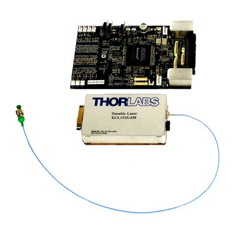
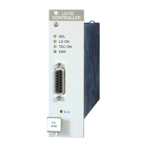
THORLABS WDM8 Series User manual

Operation Manual
Thorlabs Instrumentation
PRO8000 (-4) / PRO800
Optical Sources
WDM8xxxx
LS8xxxx
2010

________________________________________________
_______________________________________________________________________________________________________
© 2010 Thorlabs
Version: 3.1
Date: 16.09.2010
Copyright©2010, Thorlabs

_________________________________________________
______________________________________________________________________________________________________
© 2010 Thorlabs
Contents Page
1General description of the optical source modules 4
1.1 Safety 4
1.2 Properties 7
1.2.1 Protections for the laser diode 7
1.2.2 Features 8
1.3 Technical data 9
1.3.1 Common technical data for the WDM modules 9
1.3.2 Common technical data for the LS8xxxx modules 11
2Operating the PRO8000 (-4) / PRO800 optical source modules 12
2.1 Operating elements on front panel 12
2.2 Connecting an optical fiber 13
2.3 Modulating the optical source modules 13
2.3.1 Synchronous TTL modulation 13
2.3.2 Internal low frequency modulation / Coherence control 13
2.3.3 Analog modulation by an external signal source (Option) 14
2.4 External electro-optical modulation (PM output recommended) 14
2.5 Operating a WDM8xxx module 15
2.5.1 Functions in the main menu 15
2.5.2 Error messages 17
2.5.3 Functions in the channel menu 18
2.6 Operating a LS8000 module 22
2.6.1 Functions in the main menu 22
2.6.2 Error messages 24
2.6.3 Functions in the channel menu 26
3Communication with a control computer 28
3.1 General notes on remote control 28
3.1.1 Nomenclature 28
3.1.2 Data format 28
3.2 Commands of the different optical source modules 29
3.2.1 Select the module slot 29
3.2.2 WDM Modules 29
3.2.3 LS modules 39
3.3 Status reporting 42
3.3.1 Standard event status register (ESR) 44
3.3.2 Standard event status enable register (ESE) 44
3.3.3 Status byte register (STB) 45

________________________________________________
_______________________________________________________________________________________________________
© 2010 Thorlabs
3.3.4 Service request enable register (SRE) 45
3.3.5 Reading the STB by detecting SRQ 45
3.3.6 Reading the STB by *STB? command 45
3.3.7 Reading the STB by serial poll 45
3.3.8 Device error condition register (DEC) 46
3.3.9 Device error event register (DEE) 46
3.3.10 Device error event enable register (EDE) 46
3.4 IEEE error messages 47
4Service and Maintenance 48
4.1 Troubleshooting 48
4.2 Recalibration 49
5Appendix 50
5.1 Warranty 50
5.2 Thorlabs “End of Life” policy (WEEE) 51
5.2.1 Waste treatment on your own responsibility 51
5.2.2 Ecological background 52
5.3 List of acronyms and abbreviations 53
5.4 List of figures 54
5.5 Certifications and compliances 55
5.6 Copyright 56
5.7 Addresses 57

_______________________________________________
______________________________________________________________________________________________________
© 2010 Thorlabs
We aim to develop and produce the best solution for your application in the field
of optical measurement technique. To help us to live up to your expectations
and develop our products permanently we need your ideas and suggestions.
Therefore, please let us know about possible criticism or ideas. We and our
international partners are looking forward to hearing from you.
In the displays shown by the PRO8 you may find the name PROFILE.
PROFILE was the name of the manufacturer before it was acquired by Thorlabs
and renamed to Thorlabs.
Thorlabs
This part of the instruction manual contains all the specific information on how to
operate the optical source modules WDM8xxxx and LS8xxxx. A general description is
followed by explanations of how to operate the unit manually. You will also find
complete information about remote control via the IEEE 488 computer interface.
Attention
This manual contains “WARNINGS” and “ATTENTION” labels in this
form, to indicate personal danger or possible damage to equipment.
Please read these advises carefully!
NOTE
This manual also contains “NOTES” and “HINTS” written in this form.

4 Safety
________________________________________________________________________________
______________________________________________________________________________________________________
© 2010 Thorlabs
1 General description of the optical source modules
1.1 Safety
Attention
The modules ‘WDM8xxxx’ are class 1M laser sources.
Emitted wavelength: 1 single wavelength in the range 1454 nm …
1625 nm, according to ordered wavelength.
Emitted optical power: up to 50 mW, according to ordered output
power! Numerical aperture of the beam 0.11.
CAUTION – The use of optical instruments with these products will
increase eye hazard!!
INVISIBLE LASER RADIATION
DO NOT VIEW DIRECTLY WITH
OPTICAL INSTRUMENTS!
CLASS 1M LASER PRODUCT

Safety 5
_________________________________________________________________________________
______________________________________________________________________________________________________
© 2010 Thorlabs
LASER RADI ATIO N
IS EMITTED FROM
THIS APERTURE
AVOID EXPOSUR E
A
VOI D EXPOSU RE
LA SER RADI ATIO N IS EMI TTED
FROM THI S APERTURE
Attention
The laser modules supplied by Thorlabs are class 1M laser systems.
However, if you collimate or focus the laser beam you will create a
class 3R or class 3B laser system!
In that case additional safety measures have to be observed!
For the individual wavelength and output power see the certificate of
calibration supplied with the module!
Never switch on the output with no fiber connected and switch off
the output before disconnecting the fiber!
NOTE
The products are classified and labeled according to
IEC 60825-1/Am2 (2001).
If you need an additional aperture label according to CFR § 1040.10.g (5)
please use the adhesive labels delivered with the PRO8000 (-4) / 800 and
place them clearly visible for any possible user on your laser set-up!.
Two possible places for laser modules without and with modulation input
are shown below.
Without modulation input
(label 30 x 15 mm)
With modulation input
(label 20 x 15 mm)

6 Safety
________________________________________________________________________________
______________________________________________________________________________________________________
© 2010 Thorlabs
Attention
All statements regarding safety of operation and technical data in
this instruction manual will only apply when the unit is operated
correctly.
Before applying power to your PRO8000 (-4) / PRO800 system, make
sure that the protective conductor of the 3 conductor mains power
cord is correctly connected to the protective earth contact of the
socket outlet!
Improper grounding can cause electric shock with damages to your
health or even death!
Modules may only be installed or removed with the mainframe
switched off.
All modules must be fixed with all screws provided for this purpose.
Modules of the 8000 series must only be operated in the mainframe
PRO8000, PRO8000-4 or PRO800.
All modules must only be operated with duly shielded connection
cables.
Only with written consent from Thorlabs may changes to single
components be carried out or components not supplied by Thorlabs
be used.
This precision device is only dispatchable if duly packed into the
complete original packaging including the plastic form parts. If
necessary, ask for a replacement package.
Attention
Mobile telephones, cellular phones or other radio transmitters are
not to be used within the range of three meters of this unit since the
electromagnetic field intensity may then exceed the maximum
allowed disturbance values according to IEC 61326-1.
The PRO8000 (-4) / PRO800 must not be operated in explosion
endangered environments.

Properties 7
_________________________________________________________________________________
______________________________________________________________________________________________________
© 2010 Thorlabs
1.2 Properties
1.2.1 Protections for the laser diode
To protect the laser in the WDM8xxxx and LS8xxxx modules the PRO8000 (-4) /
PRO800 are equipped with the following protection circuits:
•Fixed current limit
A fixed limit set in factory protects the laser diode against operating errors.
•Electronic short-circuit switch for the laser diode
When the PRO8000 (-4) / PRO800 is switched on or off an electronic switch will
short-circuit the laser diode.
•Separate on/off function for each module
After turning on the PRO8000 (-4) / PRO800 mainframe the WDM and LS
modules are in OFF mode. They must be switched on explicitly and individually.
•Error detection
Should errors occur (for example the laser current limit set in factory has been
reached, the laser temperature is out of the allowed tolerance window), the LED
“ERR” of the module will light up. Furthermore, in case of certain errors (like
opened interlock) the output is switched off automatically.
•Over-temperature protection
Each module is protected against overheating of the output stage by an automatic
shutdown. The LED "ERR" indicates that the module is switched off. After a
decline in temperature of about 10 °C the LED "ERR" extinguishes and the output
can be reactivated.
•Mains filter
Protection against line disturbances (transients).
•Mains failure protection
In case of line failure/line damage the optical source modules are switched off
automatically and must explicitly be switched on anew.
•Key-operated power switch
Protection against unauthorized or accidental use.
•LabVIEW®-and LabWindows/CVI®drivers
For the PRO8000 (-4) / PRO800 Thorlabs supplies LabVIEW®and LabWin-
dows/CVI®-drivers for MS Windows 32.
Please refer to our homepage for the latest driver updates.
http://www.thorlabs.com

8 Properties
________________________________________________________________________________
______________________________________________________________________________________________________
© 2010 Thorlabs
1.2.2 Features
The laser fibers are connected via FC/APC connectors at the front of the module.
(Other connectors optional).
Each module is protected against overheating of the output stage by an automatic
shutdown. The LED "ERR" indicates that the module is switched off. After a decline
in temperature of about 10 °C the LED "ERR" extinguishes and the output can be
reactivated
The laser wavelength of the WDM modules is directly adjustable, whereas the rated
center wavelength of the LS8xxxx module is adjusted by operating the laser diode at
a certain user controllable temperature. The user can change the temperature (thus
the wavelength) by selecting a positive or negative temperature difference δT.
The PRO8000 (-4) / PRO800 contains a forced air cooling system with built-in fans.
Depending on the temperature the air flow of the fans is adapted automatically.
All settings can be changed with the operating elements of the mainframe or via
remote control from a PC.
The mains filter installed in the mainframe and the careful shielding of the
transformer, the microprocessor as well as the module itself provide an excellent
suppression of noise and ripple.
On request, all PRO8000 (-4) / PRO800 Optical Source Modules can be supplied in a
variety of versions, e.g. with different powers or wavelengths or modulation options.
(refer to chapter 1.3, “Technical data” starting on page 9)

Technical data 9
_________________________________________________________________________________
______________________________________________________________________________________________________
© 2010 Thorlabs
1.3 Technical data
(All technical data are valid at 23 ± 5°C and 35 ±15% humidity)
1.3.1 Common technical data for the WDM modules
General Data
Light source DFB laser diode with isolator
Operating temperature 0 … + 35 °C (non condensing)
Storage temperature - 40 … + 60 °C
Warm-up time for rated accuracy 15 min
Mechanical width of module 1 slot
Weight < 0.5 kg
Wavelength
Channel spacing ITU grid (100 GHz) 1)
Wavelengths C and L band
Tuning range ±0.85 nm
Accuracy ± 25 pm; ±10 pm (typ.)
Stability (typ.) < 0.002 nm / 24 h
Resolution 1 pm
Spectral linewidth (typ.) < 10 MHz
Output Power
Optical power (Pmax) 20 mW
Accuracy 0.6 dB (abs.), 0.4 dB (rel.)
Stability (with coherence control on) < 0.002 dB (15 s)
< 0.005 dB (15 min)
< 0.01 dB (24 h)
Setting range (attenuation, continuously variable) > 6 dB; 10 dB (typ.)
Resolution 0.01 dB
SMSR (side mode suppression ratio, at Pmax) > 40 dB typ. (> 36 dB min.)
RIN (Relative intensity noise) > 145 dB / Hz (typ.)
Optical isolation > 35 dB
1) Subject to DFB laser diode availability, 50 GHz and 25 GHz grid on request.

10 Technical data
________________________________________________________________________________
______________________________________________________________________________________________________
© 2010 Thorlabs
Coherence Control
Linewidth with modulation adjustable, up to 1GHz
Shape Noise, sine, square 1)
Bandwidth (noise) ~ 0.2 ... 5 kHz
Frequency Range (sine, square) 0.02 ... up to 50 kHz
Modulation depth (noise) 0.1...10%
Modulation depth (sine, square) 0.1...100%
ON/OFF Modulation
Frequency Range 0.02 ... up to 50 kHz
Synchronous TTL Modulation (all modules within mainframe simultaneously)
Frequency Range 0 ... 10 kHz
Input Voltage TTL
Connector (at rear panel of mainframe) BNC
Analog LF Modulation (Option)
Frequency Range DC … 50 kHz
Input Voltage Range -10 V … +10 V
Input Impedance 10 kΩ
Connector SMA
Optical Parameters
Optical output connector (standard) FC/APC 2)
Fiber PMF
3)
Safety Class 1M
1Triangle on request
2Other connector styles (SC, E2000...) and non-angled (PC) ferrule on request
3Connector key aligned to slow axis on request

Technical data 11
_________________________________________________________________________________
______________________________________________________________________________________________________
© 2010 Thorlabs
1.3.2 Common technical data for the LS8xxxx modules
General data
Light source DFB laser diode
Operating temperature 0 … + 35 °C (non condensing)
Storage temperature - 40 … + 60 °C
Warm-up time for rated accuracy 15 min
Mechanical width 1 slot
Weight < 0.5 kg
Wavelength
Wavelength / power depending on used DFB laser
Center wavelength tolerance subject to specification of used DFB laser
Stability (typ.) < 0.01 nm / 24 h
Spectral linewidth subject to specification of used DFB laser
Power
Stability (24 h) < 0.01 dB
Setting of temperature
Setting range ±5 °C
Resolution 0.001 °C
Modulation
TTL (all modules synchronous, BNC at rear of mainframe) 0 … 10 kHz
Analog modulation input (option, SMA) DC … 50 kHz
Optical parameters
Optical output connector (standard) FC/APC 1)
1Other connector styles (SC, E2000...) and non-angled (PC) ferrule on request

12 Operating elements on front panel
________________________________________________________________________________
______________________________________________________________________________________________________
© 2010 Thorlabs
2 Operating the PRO8000 (-4) / PRO800 optical source
modules
2.1 Operating elements on front panel
LED display "module selected"
LED display "module switched on"
LED display "error"
Modulation input
(SMA, optional)
Optical output
(FC/APC)
Figure 1 Front view of the WDM plug-in module

Connecting an optical fiber 13
_________________________________________________________________________________
______________________________________________________________________________________________________
© 2010 Thorlabs
2.2 Connecting an optical fiber
Depending on the construction of the optical connector the fiber is to be connected to
the optical output by means of a corresponding plug.
NOTE
Do not to confuse the FC/APC with the FC/PC connector.
The corresponding type of connector is marked on the module.
Never switch on the output with no fiber connected!
2.3 Modulating the optical source modules
The WDM modules provide different types of modulation: Synchronous modulation of
all modules within the mainframe (TTL, on/off, 0...10 kHz), internal low frequency
modulation (20 ... 50000 Hz, 0.1 ... 100 % rel. Amplitude), and optional analog
modulation by an external signal source.
2.3.1 Synchronous TTL modulation
A TTL modulation source (DC....10 kHz) is connected to the BNC connector at the
rear panel of your PRO8000 (-4) / PRO800 mainframe. All WDM modules in the
mainframe are switched on/off synchronously.
Please refer to the mainframe operation manual!
2.3.2 Internal low frequency modulation / Coherence control
The PRO8000 (-4) / PRO800 optical source modules are equipped with an adjustable
coherence control, to reduce unwanted stimulated Brillouin or Raman Scattering.
Coherence control is done by an internal amplitude modulation with a sinusoidal,
rectangular or triangular1) signal in the frequency range 20 Hz … 50 kHz, or with
band limited (1-5 kHz) white noise.
100% refers to the maximum possible modulation at a 55% setting of the maximum
output power. For larger or smaller power settings, the limits for the minimum and
maximum modulation depth will vary.
A 0% setting in the noise menu means no noise modulation, a setting of 100%
delivers a maximum of 5% amplitude modulation. This results in a maximum gauss-
shaped line-broadening of typ. more than 1 GHz.
NOTE
Percentage setting and bandwidth are not in strict linear relationship to
each other!
1Triangular on request

14 External electro-optical modulation (PM output recommended)
________________________________________________________________________________
______________________________________________________________________________________________________
© 2010 Thorlabs
2.3.3 Analog modulation by an external signal source (Option)
With this option, the optical source module can be modulated from DC to 50 kHz by
connecting an external signal source to the SMA connector at the front panel.
2.4 External electro-optical modulation (PM output recommended)
If there are still higher requirements regarding the transmission bandwidth at present
only external electro-optical modulators are used. Their inner structure mostly
resembles a Mach-Zehnder interferometer.
Modulation Input
Laser Input Laser Output
Figure 2 External electro-optical modulation
By means of 3 dB couplers the incoming light is divided into two identical beams and
recombined again at the end of the modulator. By applying voltage an electrical field
between the electrodes sets up. The applied electrical field causes changes in the
refractive index in both wave guides (Pockels effect) which are - due to the circuitry -
reversed to each other. Since the propagation speed of light depends on the
refractive index of the wave guide this results in propagation time differences and
thus in a phase difference. When both beams are recombined, light shares of
opposite phase extinguish each other - the result is an intensity modulation.
Electro-optical modulation excels in a negligible chirping and reaches a high
extinction ratio (modulation depths). The disadvantage of these modulators is their
high attenuation loss (about 4 dB) and the relatively high modulation voltages
required.
Wavelength stability with external modulation
When using external modulators a retroaction on the laser module is excluded as far
as possible if an optical isolator is used. Nevertheless, the consequent use of angle
polished connectors is recommended.

Operating a WDM8xxx module 15
_________________________________________________________________________________
______________________________________________________________________________________________________
© 2010 Thorlabs
2.5 Operating a WDM8xxx module
2.5.1 Functions in the main menu
2.5.1.1 Display
The main menu shows the channel number, the wavelength and the status of the
different inserted modules.:
channel no. cursor wavelength state
CH1 1549.31 off
CH2 1533.46 off
CH3 1553.39 off
TUNE
2.5.1.2 Selecting a module
Select a module with the cursor by pressing the softkeys and .
e.g.: CH2
The display scrolls up and down.
(The LED “SEL” on the corresponding module front panel will light up).
Press to enter the channel menu
2.5.1.3 Switching modules on and off
Modules can be switched on or off in the main menu or in the channel menu. For this
purpose first select the module (see page 15). Press the key to turn on the
module. The LED “ON” at the respective module will light up and the display shows
the emitted optical power.
Optical power
CH1 1559.31 +3.00dBm
Press the key again to turn off the module. The LED “ON” at the module
extinguishes.
CH1 1559.31 off
Attention
Never switch on the laser output with no fiber installed!

16 Operating a WDM8xxx module
________________________________________________________________________________
______________________________________________________________________________________________________
© 2010 Thorlabs
2.5.1.4 Setting of wavelength and optical power
To set the wavelength or the optical output power in the main menu the correspond-
ing module is selected with the cursor (here: CH1):
CH1 1559.31 +3.00dBm
CH2 -0.12°C off
TUNE
Pressing the key (TUNE) will turn the cursor to the right. Thus indicating the value
to be selected. The softkeys get new functions:
CH1 1559.31 +3.00dBm
CH2 -0.12°C off
TUNE: λPo
The softkey (λ) selects the wavelength, the softkey (Po) selects the optical power.
The selected value can be adjusted by means of the tuning knob. Press to
make new settings valid.

Operating a WDM8xxx module 17
_________________________________________________________________________________
______________________________________________________________________________________________________
© 2010 Thorlabs
2.5.2 Error messages
Error messages are shown in the bottom line of the display regardless of which menu
you are in.
If an error occurs, the display shows for example:
CH1 Po = +0.00dBm
LD on Po =1.0000 mW
CW δT =+0.150 °C
<CH2 OTP > ok
Channel causing the error Error message ok to confirm
Possible error messages (depending on the type of module) are:
a) Display messages while operation failure:
<CHn Vcc fail > OK Internal supply voltage failure. Please contact
Thorlabs!
<CHn OTP > OK Over Temperature Protection. Module has been
switched off due to overheating. Operation is possi-
ble again after cooling down
<CHn ctrl Temp> OK Operating temperature of the laser not yet reached
(only LS8000 sources)
b) Display messages while changing parameters:
NO PAV TUNE ! OK Attempt to change the set power with modulation
on.
NOT IF MOD ON OK Attempt to change the modulation type while
modulation is on.
AMP TOO HIGH! OK Attempt to switch on modulation when either the
sum of set power and modulation amplitude would
exceed 100% nominal power or the difference be-
tween set power and modulation amplitude would
“extinguish” the laser function.
c) Display messages when trying to switch on the module:
CHn OTP ! OK Module is overheated. Wait for cooling down.
CHn Vcc fail OK Internal supply voltage failure.
CHn ctrl Temp OK Operating temperature of the laser not yet reached
(only LS8000 sources).

18 Operating a WDM8xxx module
________________________________________________________________________________
______________________________________________________________________________________________________
© 2010 Thorlabs
2.5.3 Functions in the channel menu
You can reach the channel menu from the main menu by pressing the key .
Pressing again or will lead you back to the main menu.
2.5.3.1 Display
In the channel menu all parameters of the selected module will appear:
channel no. cursor wavelength frequency optical power
CH1 λ=1552.524nm
LD on f =193.100THz
CW Po = +3.00dBm
CHANGE
status operating mode
The and keys moves the cursor up and down and let you scroll through the
menu.
2.5.3.2 Setting the wavelength
Select the respective line with the cursor:
CH1 λ=1552.524nm
LD on f =193.100THz
CW Po= -3.00dBm
CHANGE
Press (CHANGE) to change the wavelength.
Adjust the wavelength with the tuning knob. The actual wavelength follows your input.
Press to finish the wavelength tuning and saves the data even if the
PRO800/PRO8000 (-4) is switched off.
This manual suits for next models
4
Table of contents
Other THORLABS Control Unit manuals

THORLABS
THORLABS SPCM A Series User manual

THORLABS
THORLABS TED8000 Series User manual

THORLABS
THORLABS ECL1525M-PM User manual

THORLABS
THORLABS ITC8 Series User manual

THORLABS
THORLABS ELL6 User manual
THORLABS
THORLABS LD2000R User manual

THORLABS
THORLABS PDA8000-1 User manual

THORLABS
THORLABS SPCM A Series User manual
THORLABS
THORLABS EVOA800F User manual

THORLABS
THORLABS LS5000 Series User manual